


The Modbus communication is established, the measuring instrument responds without an error message, yet the PLC displays completely implausible values. For example, 230.5 V becomes 23,050 V, a temperature appears as a negative value or an energy meter returns a figure in the billions.
In such cases, the fault is often not caused by the RS-485 connection or the measuring instrument. The transmitted registers are simply being interpreted incorrectly. Typical causes include an address offset of one register, an incorrect function code, an unsuitable data type, swapped words or an unaccounted scaling factor.
Troubleshooting should therefore begin with the unchanged raw value. The value should only be scaled and converted into the required unit once the register address, register type, data length and byte order have been confirmed.
Suitable analogue and digital interface modules can be found in the Modbus I/O section. The measuring instruments for plant and control-panel construction category provides an overview of additional displays, energy meters, signal conditioners and interfaces.
Contents
- Why does communication work despite incorrect values?
- Distinguishing between Holding Registers and Input Registers
- Correctly handling zero-based and one-based register addressing
- Correctly selecting INT16, INT32 and Float
- Distinguishing between signed and unsigned values
- Checking byte and word order
- Applying the scaling factor and unit
- Polling, update time and data consistency
- Checking the device address and communication parameters
- Checking raw registers with reference software
- Practical example: Energy meter displays an incorrect voltage
- Quickly assigning typical fault patterns
- Recommended troubleshooting procedure
- Which products are suitable?
- Conclusion
- Frequently asked questions
Why does communication work despite incorrect values?
A successful Modbus request initially confirms only that the addressed device returns a formally valid response. It does not confirm that the controller is requesting the correct register or interpreting the received bytes correctly.
For example, a device may provide two valid registers directly next to one another. If an address offset causes the frequency value to be read instead of the voltage, the device still responds without an error. The same applies if two registers belonging to a Float value are combined in the wrong order.
Troubleshooting should therefore distinguish between two levels:
- Communication level: device is reachable, telegram is valid, no timeouts or CRC errors,
- Data level: correct register, suitable function code, correct data type, correct order and scaling.
If communication is stable and the incorrect values are reproducible, the cause is usually located at the data level.
Distinguishing between Holding Registers and Input Registers
Modbus distinguishes between several data areas. Input Registers and Holding Registers are particularly relevant for measuring instruments. Both contain 16 bits, but they are read using different function codes.
| Data area | Typical function code | Access | Typical use |
|---|---|---|---|
| Coils | 01 | Read and write | Digital outputs and commands |
| Discrete Inputs | 02 | Read only | Digital states |
| Holding Registers | 03 | Read and, in some cases, write | Parameters, setpoints and some measured values |
| Input Registers | 04 | Read only | Measured values and status information |
Some devices provide process values exclusively as Input Registers. Other manufacturers store measured values in Holding Registers or permit access through both areas. The register list for the specific device is always authoritative.
If a register is requested using the wrong function code, the device either returns a Modbus exception or provides data from a different area. The address and function code must therefore always be documented together.
Correctly handling zero-based and one-based register addressing
Register addressing is one of the most frequent causes of incorrect values. Within the Modbus telegram, addressing begins at zero. However, many manuals number the first register as 1 or use reference formats such as 30001 and 40001.
Depending on the software, a data point identified as 40001 may therefore need to be entered in different ways:
- as the complete reference 40001,
- as register number 1,
- as protocol address or offset 0.
Some Modbus programs automatically subtract the area identifier and address offset. Others expect the zero-based address transmitted within the telegram. If this distinction is overlooked, an offset of exactly one register typically occurs.
Example:
- Manufacturer documentation: voltage begins at register 40001,
- actual PDU start address: 0,
- software expects an offset: enter 0,
- software expects a register number: enter 1 or 40001.
The designation of the input field is not always unambiguous. The most reliable approach is to request several consecutive registers. This makes it possible to identify the position at which a plausible raw value appears.
Correctly selecting INT16, INT32 and Float
A Modbus register always contains 16 bits. However, many measured values require a larger numerical range or decimal places and are therefore transmitted across two or four consecutive registers.
| Data type | Required registers | Typical use |
|---|---|---|
| UINT16 / INT16 | 1 | Status values, small measuring ranges and scaled values |
| UINT32 / INT32 | 2 | Meter readings, energy values and operating hours |
| IEEE-754 Float | 2 | Measured values with decimal places |
| UINT64 / INT64 | 4 | Large totalisers and long-term values |
| Double | 4 | High-resolution floating-point values |
If a 32-bit value is read as only one 16-bit register, half of the information is missing. Conversely, combining two independent 16-bit values produces a large but meaningless number.
For a 32-bit measured value, both registers should preferably be read within a single request. This prevents the value from changing between two separate requests and being assembled from two different update states.
Distinguishing between signed and unsigned values
A 16-bit register can be interpreted as either an unsigned or signed number.
- UINT16: value range from 0 to 65,535,
- INT16: value range from −32,768 to +32,767.
The same bit pattern can therefore represent two different values. A raw value of 65,530 corresponds to an unsigned value of 65,530. If the same bit pattern is interpreted as an INT16 value using two’s complement, the result is −6.
This error frequently occurs with temperatures, reactive power, power factors, bidirectional currents or flow directions. If a value that should be negative appears close to 65,535, UINT16 has probably been selected instead of INT16.
The same principle applies to 32-bit values. Whether a value is signed or unsigned must be stated explicitly in the register description.
Checking byte and word order
Within a single 16-bit register, the most significant byte is transmitted first. For measured values spanning several registers, it must additionally be clarified which register contains the most significant word.
For a 32-bit value consisting of bytes A, B, C and D, devices and software may use the following arrangements:
- ABCD: most significant word first, with the bytes inside each word unchanged,
- CDAB: words swapped,
- BADC: bytes inside each word swapped,
- DCBA: both words and bytes swapped.
Many programs refer to these functions as Byte Swap, Word Swap, Big Endian, Little Endian or Mid-Little Endian. These terms are not used consistently by every software package. The decisive factor is therefore not only the name of the setting, but the actual byte sequence produced.
A Float value of 230.0 may, for example, be represented by the hexadecimal value 4366 0000. If the two words are swapped and interpreted as 0000 4366, a completely different floating-point value is produced.
If 32-bit values are implausible, all word-order variants supported by the driver should therefore be tested systematically and compared with a known measured value.
Applying the scaling factor and unit
Not every measured value is transmitted as a finished floating-point number. Many devices use integer values with a separate scaling factor.
A register value of 2305 may, for example, mean:
2305 × 0.1 V = 230.5 V
Typical factors include:
- × 0.1 or ÷ 10,
- × 0.01 or ÷ 100,
- × 10 or × 100,
- a power of ten from a separate exponent register.
In addition to the numerical factor, the unit must also be correct. An energy meter may transmit Wh, kWh or MWh. Temperature values may be provided in °C, K or tenths of a degree. Current and voltage values may refer to primary or secondary quantities.
Double scaling is particularly common. The measuring instrument may already take the configured current- or voltage-transformer ratio into account, while the PLC multiplies by the same factor again. Conversely, an unaccounted transformer ratio can make the value appear smaller by a factor of 100 or 1,000.
Polling, update time and data consistency
An incorrect polling setting does not normally cause a constant scaling error, but it can produce outdated, fluctuating or time-shifted values.
The polling cycle should match the internal update time of the measuring instrument. If the device is requested significantly faster than it calculates new values, identical values are merely read repeatedly and the bus load increases unnecessarily.
With many devices or excessively short timeouts, responses may be lost. The controller may then continue to display the last valid value. A communication or quality status should therefore always be evaluated together with the measured value.
Several related registers should preferably be read within one telegram. This is particularly important for 32-bit and 64-bit totalisers and measured-value blocks with a common time reference.
Checking the device address and communication parameters
For Modbus RTU, the master and device must use the same serial communication parameters:
- device address,
- baud rate,
- parity,
- number of data and stop bits.
If a device responds reliably, these parameters are usually already correct. Nevertheless, duplicate device addresses or alternating responses from several devices can produce measured values that are difficult to interpret.
For Modbus TCP, the IP address, port, Unit Identifier and, where applicable, gateway assignment must also be checked. Behind a TCP/RTU gateway, the Unit Identifier frequently determines which serial device is addressed.
The device ID must not be confused with the register address. It selects the device, while the register address identifies the data point within that device.
Checking raw registers with reference software
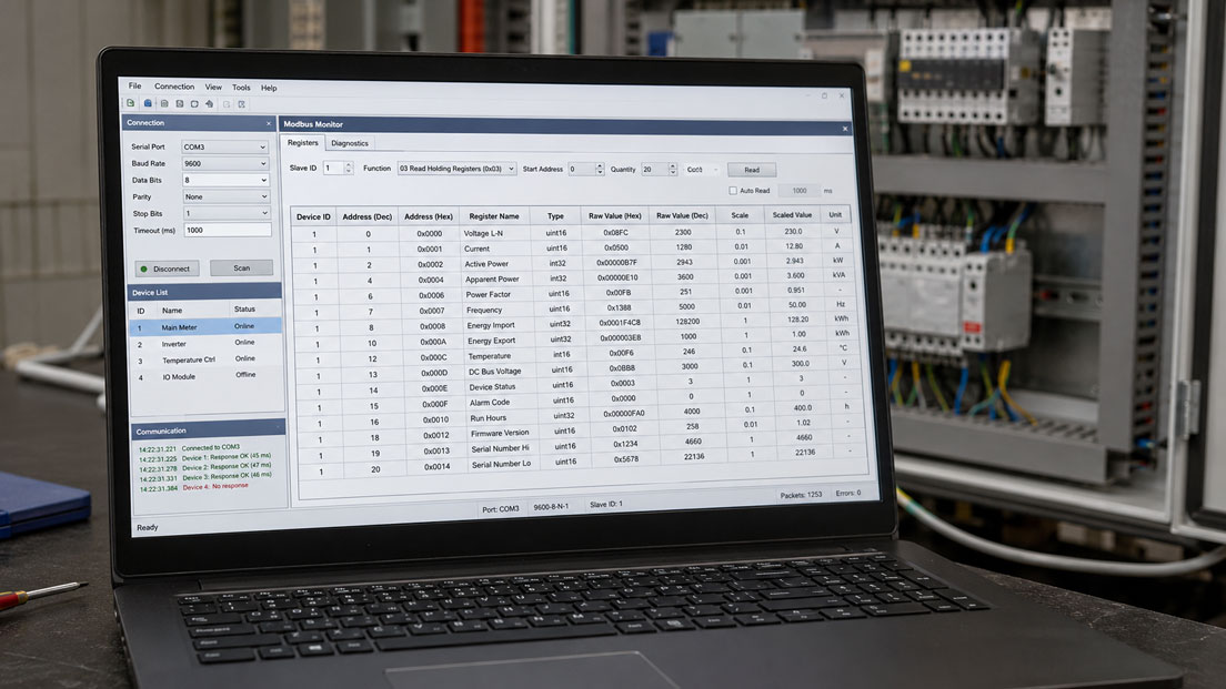
For systematic troubleshooting, the measuring instrument should first be queried independently of the PLC. With Modbus RTU, this can be done using a USB-RS485 converter and suitable Modbus client software.
The reference request should display at least:
- function code,
- start address,
- number of registers,
- raw values in decimal and hexadecimal format,
- interpreted data type,
- configured byte and word order.
A stable and easily verifiable operating condition should be used for comparison. A mains voltage, ambient temperature or defined analogue value is usually easier to evaluate than a rapidly changing power value or meter reading.
If the value is correct in the reference software, the fault is probably located in the PLC configuration. If the value is already incorrect there, the register list, device configuration, address and data format must be checked again.
Practical example: Energy meter displays an incorrect voltage
An energy meter is connected to a PLC via Modbus RTU. Communication operates without errors, but the PLC displays a mains voltage of 17,320 V. The meter display shows approximately 230 V.
According to the register list, the voltage value begins at Holding Register 40001 and is transmitted as a 32-bit Float. The PLC reads two registers beginning at address 1 and interprets them as a UINT32 value.
The inspection identifies three errors:
- The driver uses a zero-based start address. Offset 0 must be entered instead of address 1.
- The measured value is an IEEE-754 Float and not an unsigned 32-bit integer.
- The device transmits the least significant register first, which means that a Word Swap is required.
After the configuration has been corrected, the PLC displays 230.4 V. No additional scaling factor is required because the Float value is already transmitted in volts.
This example demonstrates that a stable Modbus connection does not rule out several simultaneous interpretation errors.
Quickly assigning typical fault patterns
| Fault pattern | Probable cause |
|---|---|
| Value clearly belongs to another measured quantity | Register address offset by one or more registers |
| Device responds with Illegal Function | Incorrect function code or unsupported register area |
| Value is incorrect by exactly a factor of 10, 100 or 1,000 | Scaling factor or unit not taken into account |
| Negative values appear close to 65,535 | Unsigned value used instead of signed value |
| Float value is extremely large, extremely small or NaN | Incorrect word or byte order |
| Value fluctuates irregularly | Registers read separately, timeout or duplicate device address |
| Value remains frozen while communication is temporarily interrupted | Last valid value continues to be displayed without a quality status |
| Primary value is incorrect by the transformer ratio | Current- or voltage-transformer factor is missing or has been applied twice |
Recommended troubleshooting procedure
- Document the local device value or a known reference value.
- Check the exact device version and current register list.
- Clearly determine whether Modbus RTU or Modbus TCP is being used.
- Check the device address or Unit Identifier.
- Check the function code for Holding Registers or Input Registers.
- Clarify the addressing convention used by the software.
- Read the raw registers in decimal and hexadecimal format.
- Check the number of required 16-bit registers.
- Correctly select signed, unsigned, integer or Float.
- Test Word Swap and, if necessary, Byte Swap.
- Apply the scaling factor, unit and transformer ratio.
- Adjust the polling cycle and timeout.
- Check the measured value independently of the PLC using reference software.
- Document the functioning configuration completely.
The documentation should not contain only the visible register numbers. It should also include the function code, PDU offset, data length, data type, order, factor, unit and permissible value range.
Which products are suitable?
Modbus I/O modules
The Modbus I/O category contains compact DIN-rail modules for acquiring and outputting analogue or digital signals via Modbus RTU.
The available products include:
- DMB 96100 for analogue standard signals such as 0–10 V and 4–20 mA,
- DMB 96200 with four galvanically isolated analogue inputs,
- DMB 96400 with analogue inputs and outputs,
- DMB 96500 with a universal measuring input for different industrial signals,
- DMB 96700 for digital inputs and outputs,
- DMB 96800 with four relay outputs.
For integration, the operating instructions and Modbus register manual belonging to the specific module must be used. Register lists for similar devices or different firmware versions must not be adopted without verification.
DMB 96000 Modbus RTU connection module
The DMB 96000 connects the power supply and RS-485 lines to the In-Rail bus. Termination and biasing resistors can be enabled depending on the system configuration. The module is suitable for compact, expandable Modbus I/O stations inside control panels.
USB-RS485 converter and programming interface
A USB-RS485 converter allows a service computer to be connected directly to a Modbus RTU device. This makes it possible to read raw registers independently of the PLC and control system.
This comparison request is particularly helpful when determining whether the fault is located in the measuring instrument, register interpretation or PLC program.
Additional measuring instruments for control-panel construction
The measuring instruments for plant and control-panel construction category also contains energy meters, digital displays, signal conditioners, interface converters and energy-management components.
For every Modbus integration, the device version, communication interface, register list and firmware version must be considered together.
Conclusion: Understand the raw value before applying scaling
If a Modbus device responds reliably but provides incorrect numbers, the measuring instrument is often not defective. In most cases, correct register data are being evaluated using an incorrect address, unsuitable data type or incorrect byte order.
The most important checks are the appropriate function code, zero-based or one-based addressing, number of registers, signed or unsigned interpretation, integer or Float format, and the word and byte order.
The scaling factor, unit and possible current- or voltage-transformer ratios should only be applied afterwards. An independent request using reference software and a USB-RS485 converter separates device faults from PLC and configuration errors.
Complete register documentation prevents the same errors from recurring after a controller replacement, software modification or subsequent system expansion.
Frequently asked questions about incorrect Modbus measured values
Why does the device respond even though the register address is incorrect?
The requested address may belong to another valid register. The device therefore returns a formally correct response, but the content has a different meaning.
Must Register 40001 always be entered as address 40001?
No. Depending on the software, it may expect 40001, register number 1 or the zero-based offset 0. The addressing convention of the driver must be checked.
What is the difference between Holding Registers and Input Registers?
Holding Registers are typically read using function code 03 and may sometimes be written. Input Registers are read using function code 04 and are normally read-only.
Why is a negative value displayed as approximately 65,000?
The register content is probably being interpreted as an unsigned UINT16 value instead of a signed INT16 value.
When is a Word Swap required?
A Word Swap is required for 32-bit or 64-bit values when the device provides the 16-bit registers in a different order from that used by the Modbus driver.
Why is the measured value incorrect by exactly a factor of 100?
A scaling factor of 0.01 is probably missing or has been applied twice. Confusing Wh with kWh or applying an incorrect transformer ratio can produce the same effect.
How can I determine whether the measuring instrument or PLC is configured incorrectly?
The measuring instrument should be queried using an independent Modbus client. If the value is correct there, the fault is probably located in the PLC. If the raw value is already assigned incorrectly, the register list and device configuration must be checked.