


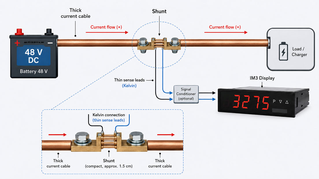
Shunt resistors, commonly referred to simply as shunts, enable high direct currents to be measured in battery systems, chargers, DC drives, test benches and power supply systems. The load current does not flow through the actual display or evaluation instrument, but through a very low-resistance precision resistor. The small voltage drop across this resistor is then evaluated as a measure of the current.
However, the selection must not be based solely on the maximum current. Rated voltage drop, resistance value, power loss, temperature rise, overload capability, mounting position and evaluation input must all be compatible. An incorrectly sized shunt can become extremely hot, cause an undesirable voltage loss or overdrive the connected measuring instrument.
Wiring is equally important. The high load current and the small measuring signal require separate connection paths. If the measuring leads are connected at unsuitable points, contact resistances and voltage drops at the current terminals can directly affect the measurement result. A four-wire or Kelvin connection prevents this error.
Suitable components can be found in the ICS category Shunt Resistors. Suitable displays and evaluation instruments are summarised under Digital Panel Meters and Digital Indicators.
Table of Contents
- How does DC current measurement with a shunt work?
- Determine the rated current and actual operating current
- Calculate the resistance value of the shunt
- Select 50, 60, 75, 100 or 150 mV
- Calculate power loss and heat generation
- Consider temperature coefficient and self-heating
- Assess pulse, starting and overload currents
- Correctly implement four-wire and Kelvin connections
- Size the main current conductors and contact points
- Plan the installation location, cooling and touch protection
- High-side, low-side and galvanic isolation
- Correctly scale the digital display and measuring range
- Measure charging and discharging currents bidirectionally
- Commissioning and plausibility checks
- Typical errors in shunt measurement
- Practical example: Measuring a 500 A battery current
- Which products and solutions are suitable?
- Conclusion
- Frequently asked questions
How does DC current measurement with a shunt work?
The shunt resistor is installed in series in the DC circuit to be measured. When current flows through the defined resistance, a proportional voltage drop is produced according to Ohm’s law:
U = I × R
The current can therefore be calculated as follows:
I = U / R
A shunt rated at 500 A / 60 mV produces a voltage drop of 60 mV at a current of 500 A. At 250 A, the signal is approximately 30 mV, and at 100 A it is approximately 12 mV.
The connected measuring instrument therefore does not measure 500 A directly. It only measures the small DC voltage across the shunt resistor and scales, for example, 0 to 60 mV to a display range of 0 to 500 A.
Current measurement is linear as long as the shunt operates within its permissible electrical and thermal load limits. Changes in the resistance value caused by temperature, overload or damaged connections directly affect the measurement result.
Determine the rated current and actual operating current
The rated current specified on the shunt is the current at which the defined rated voltage drop is produced. It should not automatically be equated with the rated current of a fuse, charger or battery.
At least the following current values are required for selection:
- normal continuous current,
- maximum continuous operating current,
- short-term peak or starting current,
- duration and repetition rate of current peaks,
- possible charging and discharging current,
- maximum fault current until the protective device disconnects the circuit.
A shunt for a normal operating current of 300 A must not automatically be rated for only 300 A if the system regularly charges at 450 A or if a DC motor draws significantly higher currents during start-up.
However, an unnecessarily large rated-current range is also disadvantageous. If a 1,000 A shunt is operated at only 50 A, a 60 mV version produces a signal of just 3 mV. This small signal makes poor use of the display input range and increases the relative influence of offset, interference and resolution.
Calculate the resistance value of the shunt
The resistance value is calculated from the rated voltage drop and rated current:
Rshunt = UN / IN
For a shunt rated at 500 A and 60 mV:
R = 0.060 V / 500 A = 0.00012 Ω
The resistance is therefore:
0.12 mΩ or 120 µΩ
Resistance values of this magnitude are so small that contact resistances at bolted connections, cable lugs or busbars can already be within a comparable range. These contact voltage drops must therefore not be included in the actual measuring voltage.
| Rated current | Rated voltage drop | Shunt resistance |
|---|---|---|
| 100 A | 60 mV | 0.6 mΩ |
| 250 A | 60 mV | 0.24 mΩ |
| 500 A | 60 mV | 0.12 mΩ |
| 1,000 A | 60 mV | 0.06 mΩ |
| 500 A | 150 mV | 0.30 mΩ |
Select 50, 60, 75, 100 or 150 mV
The rated voltage drop determines the signal produced by the shunt at rated current. Common versions operate with 50, 60, 75, 100 or 150 mV, for example.
A larger rated voltage drop generally offers the following advantages:
- larger useful signal at the evaluation input,
- better utilisation of the measuring range,
- lower relative influence of offset and electrical interference,
- often better resolution at low partial currents.
However, these advantages are offset by the following disadvantages:
- greater voltage loss in the main current circuit,
- higher power loss,
- greater heating of the shunt resistor,
- higher energy loss during continuous operation.
At a rated current of 500 A, the following values result:
| Rated signal | Resistance | Power loss at 500 A |
|---|---|---|
| 50 mV | 100 µΩ | 25 W |
| 60 mV | 120 µΩ | 30 W |
| 75 mV | 150 µΩ | 37.5 W |
| 100 mV | 200 µΩ | 50 W |
| 150 mV | 300 µΩ | 75 W |
The selection is therefore a compromise between measurement quality and loading of the current circuit. The rated voltage range must also correspond exactly to the input of the display, transmitter or control system.
Calculate power loss and heat generation
The power loss generated in the shunt can be calculated in three equivalent ways:
P = U × I
P = I² × R
P = U² / R
For a shunt rated at 500 A / 60 mV, the power loss at rated current is:
P = 0.060 V × 500 A = 30 W
This power is converted entirely into heat. A shunt is therefore not a thermally negligible measuring component and can become noticeably warm or hot during continuous operation.
Power loss increases with the square of the current. If the same 500 A shunt is loaded with only 250 A, the power loss is not 15 W, but:
P = 250² A² × 0.00012 Ω = 7.5 W
At 600 A, however, the power loss is already:
P = 600² A² × 0.00012 Ω = 43.2 W
Whether this short-term load is permissible depends on the overload capability, pulse duration, repetition rate and thermal design of the specific shunt resistor.
Consider temperature coefficient and self-heating
The resistance of a real shunt does not remain exactly constant under all conditions. It changes with temperature. Precision shunts therefore use special resistance alloys with the lowest possible temperature coefficient.
A temperature change affects the measurement in two ways:
- The ambient temperature changes the basic resistance.
- The load current additionally heats the shunt through its own power loss.
The accuracy class specified in the data sheet therefore applies only under the defined reference and installation conditions. At high ambient temperatures, with poor ventilation or when installed too tightly, the actual measurement deviation can become greater.
After a high continuous current is switched on, the shunt also requires time to reach thermal equilibrium. For precise comparative measurements, it should therefore be documented whether the value was recorded immediately after switch-on or after a defined warm-up period.
Noticeable temperature differences between the two current terminals can indicate unequal contact resistances, incorrect tightening torques or asymmetrical current supply.
Assess pulse, starting and overload currents
Short current peaks frequently occur in battery systems, welding power sources, DC drives and chargers. A shunt may tolerate current above its rated value for a short period without immediately reaching its permissible continuous temperature. However, this capability must not be assumed without verification.
The following information is required to assess pulse loads:
- maximum current level,
- pulse duration,
- duty cycle,
- repetition frequency,
- base current between pulses,
- permissible short-term overload specified by the manufacturer.
The thermal load of a current pulse depends mainly on I² × R and its duration. Two current peaks of the same magnitude can stress the shunt differently if one lasts only a few milliseconds and the other several seconds.
The display must also be suitable for the time-dependent current profile. A heavily filtered digital display may completely suppress a short peak current even though the shunt has been subjected to mechanical and thermal stress. Fast pulse currents may require a transmitter with sufficient bandwidth or separate peak-value detection.
Correctly implement four-wire and Kelvin connections
In a four-wire measurement, the main current path and voltage measurement are separated from one another. For this purpose, the shunt has two large current terminals and two separate measuring or potential terminals.
The full load current flows through the large terminals. The thin measuring leads, by contrast, only detect the voltage drop directly across the calibrated resistance element.
This prevents or significantly reduces the following voltage components from affecting the measuring signal:
- contact resistance of the current bolts,
- voltage drop across cable lugs,
- resistance of the busbar connections,
- contact ageing at the main current terminals.
The following rules apply to correct Kelvin wiring:
- Connect the measuring leads exclusively to the designated potential terminals.
- Do not tap the measuring signal arbitrarily from the main current bolts.
- Route the outgoing and return measuring leads together or as a twisted pair wherever possible.
- Maintain sufficient distance from switched power conductors and strong magnetic fields.
- Do not route the measuring leads together with highly interfering motor or contactor cables.
- Clearly identify the polarity.
Because only a very small input current flows through the measuring leads, their conductor cross-section is generally selected according to mechanical strength, voltage resistance and installation requirements. However, their insulation level must be suitable for the total system voltage. A 60 mV measuring signal can still be at a dangerously high potential relative to earth.
Size the main current conductors and contact points
The shunt is inserted into the main current circuit. Its current terminals, cable lugs and adjacent conductors must therefore be suitable for the maximum continuous current and possible short-circuit current.
The required conductor cross-section depends not only on the rated current, but also on factors including:
- conductor material,
- installation method,
- ambient temperature,
- permissible conductor temperature rise,
- cable length and voltage drop,
- bundling with other conductors,
- short-circuit withstand capability,
- manufacturer and system specifications.
The main current conductors should be connected to the shunt without mechanical stress. Rigid busbars or heavy cables must not transmit impermissible tensile, compressive or bending forces to the measuring body.
Contact surfaces must be clean, flat and suitable for the intended connection. The screws must be tightened to the specified torque. A loose connection not only increases the voltage drop but can also create a fire hazard due to local heating.
The measured value obtained through the Kelvin terminals may still appear plausible even if a main terminal is overheating. The electrical display therefore does not replace inspection of the power terminals.
Plan the installation location, cooling and touch protection
The generated heat loss must be dissipated to the surrounding environment. A shunt resistor must therefore not be installed in a small, enclosed or already heavily heated area of a control cabinet without prior verification.
The following factors in particular must be considered when planning the installation:
- specified mounting position,
- free air circulation around the resistance element,
- distance from temperature-sensitive components,
- distance from cable ducts and plastic parts,
- heat input from other power components,
- permissible ambient temperature,
- protection against accidental contact and foreign objects,
- accessibility for maintenance and retightening.
The shunt must not be thermally enclosed by a cover. At the same time, live and hot parts must be protected against accidental contact. A suitable protective cover therefore requires sufficient clearances and ventilation openings.
Battery and DC systems can produce extremely high short-circuit currents even at comparatively low voltages. Installation and maintenance may therefore only be performed in the de-energised state by appropriately qualified personnel.
High-side, low-side and galvanic isolation
A shunt can generally be installed in either the positive or negative current path. Both variants have advantages and disadvantages.
Low-side measurement
In a low-side measurement, the shunt is located in the return conductor close to the reference potential. This often reduces the common-mode voltage at the measuring instrument and simplifies signal evaluation.
However, the voltage drop across the shunt raises the potential of the load relative to the actual negative or ground point. This can influence ground references, protection functions, communication interfaces or systems connected in parallel.
High-side measurement
In a high-side measurement, the shunt is installed in the positive conductor. The ground reference of the load therefore remains unchanged. However, the measuring signal is located almost at the full system voltage.
The evaluation electronics must then safely handle both the small differential voltage and the high common-mode voltage. A galvanically isolated display or shunt/mV isolating amplifier is frequently required.
The decisive factor is not only the difference of, for example, 60 mV. It is also important to determine the potential of both measuring terminals relative to earth and the supply of the display instrument.
A non-isolated input must therefore not be connected to a shunt at an elevated potential without verification. Otherwise, measurement errors, ground loops, short circuits or damage to the evaluation electronics may occur.
Correctly scale the digital display and measuring range
The input of the display must correspond to the rated voltage drop of the shunt. A 500 A / 60 mV shunt, for example, requires an input that reliably processes 0 to 60 mV and can be scaled to 0 to 500 A.
If the shunt and display are incorrectly combined, typical errors occur:
| Shunt | Display input | Consequence |
|---|---|---|
| 500 A / 60 mV | 0–60 mV, scaled to 500 A | Correct assignment |
| 500 A / 60 mV | 0–75 mV, still scaled to 500 A | The display remains below full scale at rated current |
| 500 A / 75 mV | 0–60 mV | The input may be overdriven before rated current is reached |
| 1,000 A / 60 mV | Scaled to 500 A | The display indicates twice the actual current |
The resolution, input impedance, accuracy, update rate and galvanic isolation of the display instrument must also be checked.
If the shunt signal is to be transmitted to a PLC, an isolating amplifier can convert the small mV voltage into a more robust standard signal, for example. This also enables longer transmission distances, potential isolation and clearer fault diagnostics.
Measure charging and discharging currents bidirectionally
In battery systems, the current direction changes between charging and discharging. The polarity of the shunt voltage changes accordingly.
A shunt rated at ±500 A and ±60 mV provides, for example:
- +60 mV at 500 A in the positive direction,
- 0 mV when no current is flowing,
- −60 mV at 500 A in the opposite direction.
This application requires a display with a bipolar input or a suitable signal converter. A purely unidirectional 0-to-60 mV display cannot correctly indicate the negative voltage.
Before commissioning, it must be clearly defined which current direction is considered positive. Charging is often displayed as positive and discharging as negative, or vice versa. The important point is consistent identification in the circuit diagram, display and control system.
Commissioning and plausibility checks
After installation, the complete measuring chain should be checked. This includes the shunt, main current terminals, Kelvin leads, display and, where applicable, the isolating amplifier.
- Check the rating plate: Compare the rated current and rated voltage drop of the shunt and display.
- Check the mechanical installation: Verify mounting, clearances and stress-free connections.
- Check the tightening torques: Tighten the main current and measuring terminals according to the manufacturer’s specifications.
- Check the polarity: Clearly assign the positive and negative measuring-lead connections.
- Check the zero value: The display must show a plausible zero value when no current is flowing.
- Apply a reference current: Where possible, compare the reading with a known current or reference measuring instrument.
- Check partial loads: Compare the measured value at, for example, 25, 50 and 75% of rated current.
- Monitor the temperature: Check the terminals for unusual heating under continuous load.
- Check the current direction: Verify charging and discharging in bidirectional systems.
- Document the results: Record measured values, temperature, scaling and connection diagram.
At high currents, a complete rated-current test is not always possible on site. A plausibility check using a suitable DC current clamp or a known load can nevertheless identify wiring and scaling errors.
Typical errors in shunt measurement
| Error | Possible consequence | Suitable measure |
|---|---|---|
| Shunt selected only according to rated current | Display input and mV signal do not match | Define the rated current and rated voltage drop together |
| Power loss not calculated | Excessive heating inside the control cabinet | Calculate P = U × I at continuous and peak current |
| Measuring leads connected to the current bolts | Contact voltage drops distort the measured value | Use the designated Kelvin terminals |
| Main current cable mechanically stressed | Damage or deformation of the measuring body | Install the conductors without stress and support them separately |
| Insufficient ventilation | Temperature drift and thermal overload | Observe the manufacturer’s installation clearances and cooling requirements |
| 60 mV shunt incorrectly scaled with a 75 mV display | The display does not reach the correct full-scale value | Adapt the input range and scaling |
| High-side shunt connected to a non-isolated input | Ground loop, short circuit or equipment damage | Check the common-mode voltage and provide galvanic isolation |
| Unidirectional display used for charging and discharging current | Negative currents are displayed incorrectly or not at all | Use a bipolar input and suitable scaling |
| Loose main current connection | Local overheating despite a plausible current indication | Regularly check the contact surfaces and tightening torque |
| Parallel current path bypassing the shunt | Only part of the actual current is measured | Route the entire outgoing or return current through the shunt |
Practical example: Measuring a 500 A battery current
Charging and discharging currents of up to 500 A are to be measured in a 48 V battery system. Short-term peaks of up to 600 A may occur for several seconds. The display is installed in the control cabinet door.
A shunt rated at 500 A / 60 mV is initially selected. Its resistance is:
R = 0.060 V / 500 A = 120 µΩ
At 500 A, the power loss is:
P = 0.060 V × 500 A = 30 W
At 250 A, the shunt provides 30 mV and converts 7.5 W into heat. At a short-term current of 600 A, it produces 72 mV and an instantaneous power loss of 43.2 W. Whether this operating condition is permissible is checked using the overload data of the specific shunt.
The voltage drop of 60 mV corresponds to approximately 0.125% of the system voltage in a 48 V system. This is acceptable for the battery system. In a 12 V system, the same voltage drop would already correspond to 0.5% and could be more significant.
Because both charging and discharging currents are to be measured, a bipolar evaluation of ±60 mV is provided. The display is scaled from −500 to +500 A.
The shunt is mounted in the designated return conductor on insulated supports. The two main current cables are connected to the large current terminals and supported separately to prevent mechanical stress. Two thin, twisted measuring leads run directly from the Kelvin terminals to a galvanically isolated mV transmitter.
During initial commissioning, the display shows a small offset when no current is flowing. This is not concealed by an arbitrary change to the scaling. Instead, the polarity, measuring-lead routing, isolating amplifier and zero function are checked.
A charging current of approximately 100 A is then compared with a suitable reference measurement. The shunt voltage is approximately 12 mV, and the indication is within the expected range. After extended operation at 400 A, the temperature of the resistance element and both main current terminals is also checked.
The example shows that the current range, mV signal, heat generation, polarity and potential isolation must be planned together. The marking “500 A” alone is not sufficient for selecting the shunt.
Which products and solutions are suitable?
DER060, DER100 and DER150 Shunt Resistors
The ICS shunt resistors DER060, DER100 and DER150 are used to extend the measuring ranges of DC current indicators.
Depending on the version, DC current ranges from 1 to 6,000 A and rated voltage drops of 60, 100 or 150 mV are available. The rated current, output voltage, mechanical dimensions, thermal load and connected measuring instrument must be coordinated during selection.
IM1 Digital Display for Shunt Signals
Depending on the version, the IM1 digital display processes shunt signals from 0 to 60 mV or 0 to 150 mV. The display range can be adapted to the rated current of the shunt being used.
It is suitable, for example, for local current indication in chargers, DC power supplies, battery cabinets and industrial switchgear.
IM2 and IM3 for Extended Evaluation Functions
The IM2 and IM3 digital display series are available for different mV input ranges. Depending on the version, they offer additional functions such as limit values, analogue outputs, relays, minimum/maximum memory and flexible scaling.
Before selection, it must be checked whether a unipolar or bipolar input is required and whether the galvanic isolation is sufficient for the potential of the shunt.
DS 75000 Shunt/mV Isolating Amplifier
The DS 75000 is used for galvanic isolation and conversion of unipolar and bipolar mV signals. It is particularly suitable when a shunt is located at a higher potential, the signal must be transmitted over a longer distance or converted into a standard signal for a PLC.
ICS Schneider Messtechnik provides support in selecting the rated current, mV output, digital display, signal converter and potential isolation, as well as in coordinating the measuring range, scaling and installation conditions.
Conclusion
A shunt resistor makes high direct currents measurable by producing a small proportional voltage drop. However, selecting a suitable shunt requires considerably more than specifying the maximum current.
The resistance and power loss are determined by the rated current and rated voltage drop. A higher mV signal improves evaluation but also increases the voltage drop and heat generation. Particularly at currents of several hundred or thousand amperes, even a few additional millivolts can convert into considerable heat.
For accurate measured values, the main current path and voltage measurement must be separated. The Kelvin leads must be connected directly to the designated measuring terminals of the shunt. Contact resistances at the power terminals must not form part of the measuring signal.
The main current conductors, bolted connections, installation cooling, touch protection and short-circuit withstand capability are just as important as the accuracy class. With high-side measurements and battery systems at elevated potential, the common-mode voltage of the display must also be considered or galvanic isolation must be provided.
Reliable DC current measurement is only achieved when the shunt, cable routing, digital display and operating conditions are designed as a complete measuring chain and tested together after installation.
Frequently asked questions about shunt resistors for direct current
How is the resistance of a shunt calculated?
The resistance is calculated by dividing the rated voltage drop by the rated current. A shunt rated at 500 A and 60 mV has a resistance of 0.060 V / 500 A = 120 µΩ.
What is the power loss of a 500 A / 60 mV shunt?
At rated current, the power loss is 0.060 V × 500 A = 30 W. At half the current, the power loss is only 7.5 W because of the quadratic relationship.
Is a 75 mV shunt more accurate than a 60 mV shunt?
Not automatically. The larger signal can improve the resolution and interference immunity of the evaluation system. At the same time, it causes a higher voltage drop and greater power loss. Accuracy depends on the shunt, display, temperature and wiring.
Why does a shunt require four terminals?
Two terminals carry the high load current. Two separate Kelvin terminals measure the voltage drop directly across the calibrated resistance element. This significantly reduces the effect of contact resistances at the main current terminals on the measured value.
May the measuring leads be attached to the large current bolts?
Only if the manufacturer explicitly designates them as measuring points. As a general rule, the separate potential terminals must be used so that contact resistances at the current terminals do not affect the measurement.
Can a shunt measure charging and discharging current?
Yes. The polarity of the voltage drop changes when the current direction is reversed. A bipolar display or suitable transmitter is required for this purpose.
Should the shunt be installed in the positive or negative conductor?
This depends on the grounding concept, protection functions and evaluation input. Low-side measurement is often electrically simpler but changes the reference potential. High-side measurement frequently requires galvanically isolated evaluation.
Can a shunt briefly carry more than its rated current?
Depending on the design, a short-term overload may be permissible. The decisive factors are the current level, pulse duration, repetition rate and manufacturer specifications. The permissible overload must not be used as a continuous measuring range.
Why does a shunt become hot despite its extremely low resistance?
At high currents, even a resistance of only a few microohms produces considerable power loss. At 1,000 A and 60 mV, for example, 60 W of heat is generated.
Why does the display indicate an incorrect current?
Common causes include incorrect mV scaling, reversed polarity, unsuitable measuring points, a parallel current path, temperature drift, loose main terminals or an unsuitable or non-isolated input.