 Datasheet
The input and output range of DS 75000 can be easily set by using DIP switch. Due to the calibrated range selection no further adjustment is necessary.
A switchable compensation of the measuring range can be performed at the Zero/Span potentiometers on the front panel. Also the cut-off frequency can be adapted to the measurement task by using the DIP Switch.
The auxiliary power can be supplied via the connection terminals or via the optional In-Rail-Bus connector. A green LED on the front of the unit has been provided to monitor the power supply.
Product line
| Device Type | Order No. |
|---|---|
| Shunt/mV Isolation Amplifier, calibrated range selection | DS 75000 S |
| Shunt/mV Isolation Amplifier, calibrated range selection, In-Rail-Bus for power supply |
DS 75000 B |
Technical Data
Input
| Input signal (switch selectable) |
±60 mV, ±100 mV, ±150 mV, ±250 mV, ±300 mV, ±500 mV 0 to 60 mV, 0 to 100 mV, 0 to 150 mV, 0 to 250 mV, 0 to 300 mV, 0 to 500 mV |
| Input resistance | ≥ 100 kOhm |
| Overload | ≤ 30 V |
Output
| Current | Voltage | |
| Output signal (switch selectable) |
±20 mA, 0 to 20 mA, 4 to 20 mA ±10 mA, 0 to 10 mA, 2 to 10 mA |
±10 V, 0 to 10 V, 2 to 10 V ±5 V, 0 to 5 V, 1 to 5 V |
| Load | ≤ 12 V (600 Ohm at 20 mA) | ≤ 5 mA (2 kOhm at 10 V) |
| Linear transmission range | unipolar: –1 to +110 %, bipolar: –110 to +110 % | |
| Residual ripple | < 10 mVrms | |
General Data
| Transmission error | < 0.1 % full scale | |
| Temperature coefficient 1) | < 100 ppm/K | |
| Zero/Span compensation | ± 5 % of measuring range | |
| Cut-off frequency -3 dB | 8 kHz, switchable to 100 Hz | |
| Response time T99 | 100 µs, 7 ms | |
| Test voltage | 3 kV AC, 50 Hz, 1 min., Input against output against power supply |
|
| Working voltage 2) (Basic Insulation) |
600 V AC/DC for overvoltage category II and pollution degree 2 acc. to EN 61010-1 |
|
| Protection against electrical shock 2) |
Protective separation according to EN 61140 by reinforced insulation in accordance with EN 61010-1 up to 300 V AC/DC for overvoltage category II and pollution degree 2 between all circuits. |
|
| Ambient temperature | Operation Transport and storage |
–25 °C to +70 °C (-13 to +158 °F) –40 °C to +85 °C (-40 to +185 °F) |
| Power supply | 24 V DC 9.6 V to 31.2 V, approx. 0.8 W | |
| EMC 3) | EN 61326-1 | |
| Approvals | UL (USA/Canada): UL 61010, Class I, Div. 2 ATEX / IECEx: Zone 2 (nA) |
|
| Construction | 6.2 mm (0.244″) housing, protection class: IP 20 mounting on 35 mm DIN rail acc. to EN 60715 |
|
| Connection | Captive plus-minus clamp screws Wire cross-section max. 2.5 mm² / AWG 14 Stripped length 6 to 8 mm / 0.28 in Screw terminal torque 0.8 Nm / 7 lbf in |
|
| Weight | Approx. 70 g | |
- Average TC related to full scale value in specified operating temperature range, reference temperature 23 °C
- For applications with high working voltages, ensure there is sufficient spacing or isolation from neighboring devices and protection against electric shocks.
- Minor deviations possible during interference
Block diagram
Dimensions
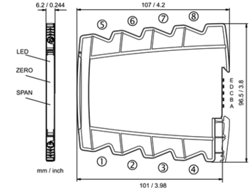
Terminal assignments
- 1 +Input
- 2 −Input
- 3n.c.
- 4n.c.
- 5 +Output
- 6 −Output
- 7 +Power supply 24 V DC
(connected to In-Rail-Bus) - 8 −Power supply 24 V DC
(connected to In-Rail-Bus)
Optional power connection via In-Rail-Bus (see accessories)


