


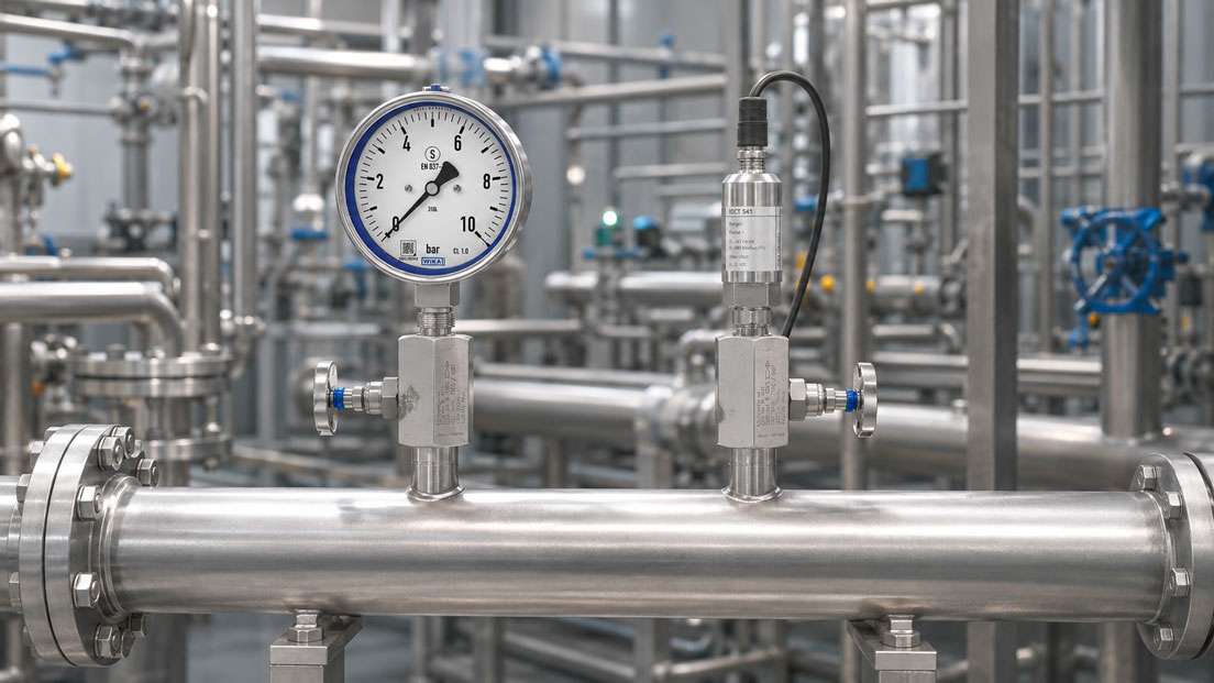
Measuring oxygen pressure requires considerably more than selecting a suitable measuring range and process connection. Although oxygen itself is not combustible, it supports combustion reactions much more strongly than normal ambient air. Materials, contamination or installation aids that appear harmless under ordinary conditions can react violently in pressurised oxygen.
Oils, greases, hydrocarbons, unsuitable thread sealants, fibres, metal particles and residues from manufacturing or installation are particularly critical. If such contamination encounters a suitable ignition source, a rapid combustion reaction can occur inside a pressure gauge, pressure sensor or valve.
A pressure measuring instrument for oxygen must therefore not only be resistant to the medium. The complete configuration comprising the measuring element, process connection, seals, valves and accessories must be confirmed as suitable for oxygen, the maximum pressure, temperature, concentration and operating conditions. In addition, the wetted measuring chain must be cleaned, inspected, marked, protectively packaged and installed under clean conditions according to a defined procedure.
Suitable instruments and components can be found in the ICS category Pressure Measurement Technology. Electronic transmitters for process and plant applications are grouped under Pressure Sensors and Differential Pressure Sensors.
Table of Contents
- Why is pressurised oxygen particularly critical?
- What does suitability for oxygen service mean?
- Correctly assessing oil- and grease-free cleaning
- Avoiding pressure surges and possible ignition sources
- Selecting pressure gauges for oxygen
- Selecting electronic pressure sensors
- Correctly designing valves and shut-off fittings
- Checking materials and seals
- Defining the process connection and sealing system
- Determining the measuring range and overload reserve
- Ensuring clean installation and storage
- Planning commissioning and replacement
- Distinguishing between industrial and medical oxygen
- Practical example: Oxygen line at 40 bar
- Typical errors at oxygen measuring points
- Checklist for selecting instruments
- Which products and solutions are suitable?
- Conclusion
- Frequently asked questions
Why is pressurised oxygen particularly critical?
Combustion requires an oxidising agent, combustible material and sufficient ignition energy. In an oxygen system, the oxidising agent is already present at a high concentration. Even small quantities of organic or inorganic contamination may therefore be sufficient to act as fuel.
Possible combustible substances within a pressure measuring point include:
- oil and grease residues from manufacturing or installation,
- cutting, drawing or cooling lubricants,
- unsuitable thread pastes and sealants,
- organic fibres and packaging residues,
- dust, paint particles or plastic abrasion,
- unsuitable seals or lubricants inside valves,
- residues from cleaning agents or solvents.
The risk does not increase solely with static pressure. Other decisive factors include the oxygen concentration, temperature, rate of pressure change, flow velocity, geometry, particle loading and the materials used.
A component that can be used safely at low pressure is therefore not automatically suitable for high cylinder pressures or rapid pressurisation.
What does suitability for oxygen service mean?
The designation “suitable for oxygen” should always refer to a specific configuration and defined operating conditions. A general material designation such as stainless steel, brass or FKM is not sufficient.
At least the following information is required for the assessment:
- oxygen concentration and purity,
- gaseous or liquid oxygen,
- maximum operating and test pressure,
- minimum and maximum temperature,
- static or dynamic pressure loading,
- possible pressure surges and opening speed,
- wetted materials and seals,
- cleanliness level and permissible residual contamination,
- process connection and sealing system used,
- application area, for example industry, medicine or welding technology.
An oil- and grease-free component is not automatically fully suitable for oxygen service. Cleaning removes possible fuels, but does not by itself confirm the suitability of all materials, seals, geometries and operating conditions.
Conversely, a material that is generally suitable must not be used without defined cleaning. Oxygen compatibility and cleanliness must therefore always be considered together.
Correctly assessing oil- and grease-free cleaning
During oxygen cleaning, the wetted surfaces are freed from hydrocarbons, particles, fibres and other foreign substances using a defined procedure. The remaining residues may subsequently be tested.
A complete process chain may include:
- cleaning the individual parts or the assembled instrument,
- flushing or recleaning the wetted areas,
- drying using a suitable clean medium,
- visual inspection and, where applicable, residual contamination testing,
- assembly under controlled clean conditions,
- sealing the process connection with a protective cap,
- packaging in a sealed clean plastic bag,
- marking the oxygen-service or cleanliness configuration.
“Oil- and grease-free” does not necessarily mean completely free from every measurable hydrocarbon. Defined limits and test methods are used in practice. For critical applications, it should therefore be clarified according to which specification the component was cleaned and whether a test certificate is available.
If the operator requires a specific maximum residual hydrocarbon content or a defined particle class, this must be specified when ordering. A subsequent general statement that the product “was cleaned” is not sufficient as evidence.
Avoiding pressure surges and possible ignition sources
Even with a clean configuration, unfavourable operating conditions can create an ignition hazard. Rapid pressurisation of a previously unpressurised dead volume is particularly relevant.
Adiabatic compression
If a valve is opened very quickly, the incoming oxygen gas can be strongly compressed inside a small enclosed space. This can cause the local gas temperature to rise significantly for a short period.
Particle impact
Loose metal or dirt particles can be accelerated by a high flow velocity and strike valve seats, changes in direction or measuring elements. The resulting local heating may act as an ignition source.
Friction and mechanical contact
Unsuitable valve designs, damaged components or high operating speeds can generate frictional heat. A sticking valve seat must also not be operated using excessive force or unsuitable tools.
Resonance and rapid flow
Certain piping geometries, blind holes and small dead spaces can create unfavourable thermal and acoustic conditions during rapid gas flow.
Valves in oxygen systems are therefore opened slowly and in a controlled manner. Pressure surges must not simply be addressed using any commercially available snubber. The snubber must also be suitable for oxygen, cleaned and rated for the actual pressure.
Selecting pressure gauges for oxygen
Mechanical pressure gauges provide a clearly visible pressure indication without requiring an electrical power supply. However, only variants that have been explicitly designed and cleaned for oxygen applications may be used.
The following points must be checked during selection:
- material of the Bourdon tube or diaphragm measuring system,
- oxygen compatibility of the wetted soldered and welded joints,
- oil-free manufacturing and defined oxygen cleaning,
- suitable process connection without unnecessary dead spaces,
- indication range and permissible overload,
- safety design of the case,
- temperature and ambient conditions,
- vibration and dynamic pressure loading.
Safety version with a solid baffle wall
For gaseous media at higher pressures, a safety version with a solid baffle wall, safety glass window and rear pressure relief is advisable. If the measuring element ruptures, escaping medium and components are preferentially directed towards the rear of the case.
The pressure gauge must be installed accordingly. There must be no closed wall or cover behind the rear pressure-relief device that could obstruct the intended pressure relief.
Unfilled or liquid-filled case?
An unfilled pressure gauge contains no damping fluid inside the case. In a liquid-filled pressure gauge, a filling liquid reduces pointer movement caused by vibrations and pulsating pressure.
The case filling is normally separated from the process. Nevertheless, it must not be concluded from this alone that every standard liquid-filled version is suitable for oxygen. Manufacturer approval, constructive separation, the cleaning process and the permissible operating conditions must be confirmed for the specific variant.
For a dedicated oxygen measuring point, a case filling should only be provided if required by the plant conditions and included in the confirmed oxygen-service configuration.
Selecting electronic pressure sensors
Electronic pressure sensors provide continuous signals such as 4–20 mA, 0–10 V, IO-Link or Modbus. They are suitable for control systems, alarm functions, data recording and remote monitoring.
Welded stainless-steel measuring cells are often advantageous for oxygen applications because they can be designed without an elastomeric process seal and without internal pressure-transmission fluid. However, this does not replace confirmed suitability for oxygen service and the required cleaning.
The following points must be checked:
- complete list of wetted materials,
- presence of internal pressure-transmission fluid,
- design of the process seal,
- cleaning standard and marking,
- permissible oxygen pressure and temperature range,
- overload and burst pressure,
- resistance to pressure spikes,
- electrical connection and ingress protection,
- required accuracy and long-term stability.
Depending on the sensor, an “oil- and grease-free” option may also be offered for other clean gases. For oxygen, it must nevertheless be explicitly confirmed that the selected combination of measuring range, process connection, seal and material is supplied as an oxygen-service version.
Correctly designing valves and shut-off fittings
A suitable measuring instrument loses its safety advantage if an unsuitable or contaminated valve is installed upstream. The pressure gauge valve is part of the wetted measuring chain and must meet the same oxygen-service and cleanliness requirements.
The following points are particularly relevant when selecting a valve:
- valve body and stem material,
- seat and packing materials,
- lubricants inside the valve,
- flow cross-section and flow velocity,
- opening and closing characteristics,
- maximum differential pressure during opening,
- dead spaces and possible particle accumulation,
- vent and test connections,
- cleaning and packaging condition.
The valve should permit slow and controlled pressurisation. Depending on pressure and geometry, a fast-switching ball valve directly upstream of a small measuring chamber may be less suitable than a correspondingly designed, slowly opening instrument valve.
Test and vent connections must be sealed cleanly. The sealing plugs and sealing elements also require confirmed oxygen compatibility.
Checking materials and seals
The oxygen compatibility of a material is not an unchanging material property. It depends, among other things, on pressure, temperature, oxygen concentration, component geometry, material thickness, flow and possible ignition energy.
Metallic materials
Stainless steel and copper alloys are frequently used in oxygen systems. However, this does not constitute general approval for every pressure and every design. Thin measuring elements, valve seats and components exposed to high flow velocities may behave differently from solid piping components.
Non-metallic materials
Seals, packings, diaphragms and plastics often have a greater influence on ignition and combustion behaviour than the metallic valve body. The sealing material must therefore be explicitly assessed for the actual oxygen-service conditions.
A general chemical compatibility table is not sufficient. It normally describes chemical resistance but does not necessarily assess ignition behaviour in pressurised oxygen.
When ordering, the material and seal should not be specified independently of pressure and temperature. A seal that is permissible at 10 bar may require a different assessment at a significantly higher pressure.
Defining the process connection and sealing system
The process connection must mechanically match the mating connection and be installed using a sealing principle suitable for oxygen service.
Examples include:
- parallel threads with a defined seal,
- tapered threads with thread sealant,
- metal-sealing high-pressure connections,
- cutting-ring or compression fittings,
- flange connections and VCR-type high-purity gas connections.
With parallel threads, sealing must not take place uncontrolled via the thread if a flat, profile or metallic seal is specified by the design.
PTFE tape, thread paste and other sealants may only be used if explicitly approved for the oxygen application and operating conditions. Protruding tape or hardened sealant residues can form particles and enter the system.
The process thread of a cleaned instrument must not come into contact with oil-contaminated thread gauges, dirty tools or unsuitable assembly pastes.
Determining the measuring range and overload reserve
The measuring range must not be selected solely on the basis of the normal operating pressure. Start-up processes, pressure regulator failures, thermal pressure increases, pressure surges and the maximum possible supply pressure must also be considered.
A suitable indication range provides:
- sufficient resolution within the normal working range,
- reserve above the normal operating pressure,
- sufficient overload protection,
- clear visibility of warning and limit ranges.
The measuring range stated on the instrument must not be confused with the permissible overload or burst pressure. Likewise, a high burst pressure must not be interpreted as the permissible operating pressure.
For pressure sensors, it must also be checked whether the required accuracy is specified as a percentage of full scale or of the measured value. An unnecessarily large measuring range can increase the absolute measurement uncertainty during normal operation.
Ensuring clean installation and storage
A factory-cleaned oxygen measuring instrument can be contaminated again through improper storage or installation.
The following principles apply in particular to storage and installation:
- Only remove the protective cap and plastic packaging immediately before installation.
- Do not store instruments uncovered in workshops or tool cases.
- Use only clean, suitable tools that are preferably reserved exclusively for this purpose.
- Wear clean, lint-free gloves.
- Do not touch process connections with bare or dirty hands.
- Do not use conventional assembly greases or corrosion-protection oils.
- Clean and flush the piping according to the defined procedure before installation.
- Reseal open connections during interruptions in the work.
A component that has been placed on an oil-contaminated workbench must not be installed in an oxygen system without being professionally cleaned again.
Cleaning on site using arbitrary brake cleaner, alcohol or compressed air does not replace qualified oxygen cleaning. Cleaning agents can leave residues, damage materials or introduce additional contamination.
Planning commissioning and replacement
The complete measuring point should be checked before it is pressurised for the first time:
- Compare the order and instrument data with the process conditions.
- Check the marking of the oxygen-service or oil- and grease-free configuration.
- Check that the protective packaging is undamaged.
- Compare the materials and seals with the approved specification.
- Ensure the cleanliness of the piping and connections.
- Perform the installation using approved sealing elements.
- Align the measuring instrument correctly without mechanical stress.
- Initially keep the valves closed.
- Build up the pressure slowly and in a controlled manner.
- Observe the leak tightness and measured value.
- Check the final valve positions and operational markings.
When replacing an instrument, the system must be depressurised and isolated in accordance with the operational safety instructions. A removed oxygen instrument must not automatically be used for other media and subsequently reinstalled in the oxygen system without renewed cleaning.
After contact with oil, grease or an unknown medium, the original oxygen cleanliness is no longer verified.
Distinguishing between industrial and medical oxygen
The fundamental hazards associated with oxygen apply to both industrial and medical systems. Medical oxygen systems are, however, subject to additional requirements relating to medical devices, gas quality, prevention of misconnections, documentation, hygiene and risk management.
A component supplied according to an industrial cleaning procedure is therefore not automatically approved for a medical oxygen system. Likewise, a reference to ISO 15001 must not be interpreted as full medical approval without checking the specific product.
For applications in hospitals, ventilation systems or medical gas supply systems, the applicable product-specific and regulatory requirements must be checked separately.
Practical example: Oxygen line at 40 bar
The pressure of a gaseous oxygen line in an industrial plant is to be monitored. The normal operating pressure is 35 bar. During commissioning and control operations, the pressure may briefly rise to 42 bar.
The following are required:
- a clearly visible local pressure indication,
- an electronic signal for the control system,
- a shut-off option for maintenance and instrument testing,
- an oil- and grease-free configuration confirmed for oxygen service.
Pressure gauge
An indication range of 0 to 60 bar may be selected, for example. This places the normal operating pressure within an easily readable area and provides reserve for the known pressure spikes.
Because the medium is gaseous and the application is safety-relevant, a stainless-steel pressure gauge in a safety version with a solid baffle wall is selected. It is explicitly ordered as a cleaned oxygen-service version and remains sealed in its packaging until installation.
Pressure sensor
A pressure transmitter with a welded stainless-steel measuring cell and a measuring range of 0 to 60 bar is used for the control signal. The selected order configuration must be explicitly confirmed as oil- and grease-free and suitable for oxygen at a minimum pressure of 42 bar and the applicable temperature.
Pressure gauge valve
An instrument valve that permits slow and controlled pressurisation is installed between the process line and the measuring instruments. The valve body, seat, stem seal, sealing plugs and all sealing elements are specified as a complete oxygen-service configuration.
Installation
The cleaned components are unpacked only immediately before installation. Conventional thread pastes and assembly greases are not used. After installation, the valve is opened slowly while the pressure gauge and electronic signal are monitored.
The decisive factor is not simply that every individual component is made of stainless steel. A suitable measuring point is created only by the confirmed combination of oxygen compatibility, cleaning, seals, measuring range, valve and clean installation.
Typical errors at oxygen measuring points
| Error | Possible consequence | Suitable corrective action |
|---|---|---|
| Standard pressure gauge used without an oxygen-service configuration | Unknown residues and unconfirmed materials | Order an explicitly cleaned and approved configuration |
| “Stainless steel” treated as equivalent to “suitable for oxygen” | Seals and design remain unevaluated | Check the complete instrument configuration |
| Only oil- and grease-free cleaning considered | Material or pressure limits are overlooked | Confirm cleaning and oxygen compatibility separately |
| Valve opened too quickly | Adiabatic heating and pressure surge | Build up pressure slowly and in a controlled manner |
| Unsuitable thread paste used | Combustible residue inside the oxygen system | Use only explicitly approved sealants |
| Protective cap removed too early | Particle and hydrocarbon contamination | Open the packaging only immediately before installation |
| Cleaned instrument installed using oil-contaminated tools | Renewed contamination of the connection | Provide clean and suitable tools |
| Arbitrary pressure snubber retrofitted | Additional unverified component in the oxygen flow | Use only cleaned components suitable for oxygen service |
| Measuring range selected without reserve for pressure spikes | Overload or permanent measurement deviation | Consider the maximum possible operating conditions |
| Removed instrument used with oil and subsequently reinstalled | Oxygen cleanliness is no longer ensured | Professionally clean and requalify the instrument or replace it |
Checklist for selecting instruments
- Is the oxygen gaseous or liquid?
- What oxygen concentration is present?
- What are the operating, maximum and test pressures?
- What minimum and maximum temperatures occur?
- Are rapid pressure changes or pressure surges possible?
- What measuring range and accuracy are required?
- Which wetted materials are intended?
- Have all seals been confirmed for the operating conditions?
- Has the instrument been explicitly cleaned to be oil- and grease-free?
- According to which specification was the cleaning performed?
- Is a cleaning certificate or acceptance test certificate required?
- Has the complete order configuration been approved for oxygen?
- Are the valve, fittings and sealants also suitable?
- How will the clean packaging be preserved until installation?
- How will pressure be built up slowly during commissioning?
Which products and solutions are suitable?
WIKA models 232.30 and 233.30
The WIKA Bourdon tube pressure gauges 232.30 and 233.30 are stainless-steel pressure gauges in a safety version. The solid baffle wall and rear pressure relief provide increased personal protection in the event of measuring-element failure.
An arbitrary standard version must not be used for oxygen. The measuring range, measuring system, process connection, case filling and cleaning option must be ordered and confirmed as one complete oxygen-service configuration.
WIKA models 232.50 and 233.50
The WIKA Bourdon tube pressure gauges 232.50 and 233.50 are made of stainless steel and cover numerous industrial measuring ranges. They can serve as a design basis for project-specific measuring points.
For oxygen applications, an explicitly cleaned version confirmed for the specific pressure is also required. For higher safety requirements, it should be checked whether a safety version with a solid baffle wall is preferable.
IDCT541 pressure sensor
The IDCT541 is a stainless-steel pressure sensor with an RS485 and Modbus RTU interface. It is available in an oil- and grease-free configuration based on defined cleaning requirements and is intended, among other applications, for technical gases such as oxygen.
Before selection, the measuring range, process connection, temperature and maximum oxygen pressure must be checked against the specific order configuration.
IMP335 pressure transmitter
The IMP335 features a welded stainless-steel sensor without internal pressure-transmission fluid. It is suitable for industrial pressure measurement and is available in a version intended for oxygen applications.
The oxygen option must be ordered explicitly. The process connection, measuring range and any seal must be assessed together.
IMP336 pressure transmitter
The IMP336 uses wetted components made from special stainless steel and is available in an oil- and grease-free configuration. In addition to hydrogen applications, the corresponding configuration can also be used for technical gases such as oxygen.
The specific suitability must be confirmed according to the pressure, temperature, connection and cleaning requirements.
IMP17.600 G and IMP26.600 G
The IMP17.600 G is available in an oxygen-service version and as a special oil- and grease-free version. Depending on the configuration, the IMP26.600 G can also be supplied with a corresponding special option.
The options “oxygen-service version” and “oil- and grease-free” must not automatically be regarded as identical. The required combination must be specified when ordering.
WIKA CPG1500 precision digital pressure gauge
The WIKA CPG1500 is suitable for precise pressure testing and calibration tasks. A special oil- and grease-free oxygen option with additional inspection of the wetted areas is available from the manufacturer for oxygen applications.
An oxygen calibration instrument must also not be operated with oil-contaminated pressure generators, hoses or adapters. The complete test equipment must be clean and suitable for oxygen service.
AS-Schneider pressure gauge valves, types GS and GA
The pressure gauge valves, type GS, and the pressure gauge valves, type GA, are used to shut off pressure gauges, pressure transmitters and pressure switches. The GA version additionally features a vent or test connection.
The standard configuration shown on the product pages is not automatically an oxygen-service version. For oxygen, the materials, seat, packing, cleaning, lubricants and maximum operating pressure must be confirmed for the specific project.
ICS Schneider Messtechnik provides support in selecting the pressure gauge, pressure sensor, pressure gauge valve, process connection and seal, as well as defining the measuring range, oxygen-service configuration, cleaning requirements and required test certificates.
Conclusion
Safe oxygen pressure measurement is not achieved simply by selecting a pressure gauge or sensor made of stainless steel. The decisive factor is confirmed suitability of the complete measuring point for the oxygen concentration, pressure, temperature and operating conditions.
Oil- and grease-free cleaning reduces the risk caused by combustible residues. However, it does not replace the assessment of materials, seals, valve geometry, process connections and possible pressure surges.
For gaseous oxygen at elevated pressure, pressure gauges should preferably be used in a suitable safety version. For electronic sensors, welded measuring cells without internal pressure-transmission fluid offer design advantages, provided that the specific configuration has been confirmed for oxygen service.
Valves, fittings, seals and calibration accessories are part of the same measuring chain. A single unsuitable or contaminated component can compromise the cleanliness of the complete measuring point.
The protective packaging must only be opened immediately before installation. Clean tools, approved sealing elements and slow, controlled pressurisation are essential parts of commissioning.
Frequently asked questions about oxygen pressure measurement
Is oxygen itself combustible?
No. Oxygen is not itself a fuel, but it strongly supports combustion reactions. Materials can ignite more easily in concentrated oxygen and burn much more violently than in normal air.
Is the designation “oil- and grease-free” sufficient?
No. The materials, seals, design, pressure, temperature and operating conditions must additionally be suitable for oxygen service. Particles and other foreign substances must also be considered.
Can every stainless-steel pressure gauge be used for oxygen?
No. Stainless steel alone confirms neither the oxygen compatibility of the complete design nor the required cleanliness level. The instrument must be explicitly supplied as a suitable oxygen-service version.
Can a glycerine-filled pressure gauge be used?
Only if the specific liquid-filled version has been confirmed by the manufacturer for the oxygen application. Although the case filling is normally separated from the process, the design and possible failure scenarios must still be assessed.
Why must oxygen valves be opened slowly?
Rapid pressurisation can generate strong adiabatic heating inside small dead spaces. Particles can also be accelerated by the high flow velocity.
Can PTFE tape be used for sealing?
Only if the specific sealing material and installation procedure have been explicitly approved for the oxygen application. Protruding or cut tape must not enter the gas path.
Can a pressure sensor that has already been used be cleaned subsequently for oxygen service?
This depends on the design, the previous medium and the availability of a qualified cleaning process. Replacement may be required if the contamination is unknown or inaccessible dead spaces are present.
Does the pressure gauge valve also have to be oil- and grease-free?
Yes. All wetted components of the measuring point, including the valve, adapters, sealing plugs and seals, must meet the defined oxygen-service and cleanliness requirements.
Does ISO 15001 apply to every industrial oxygen system?
No. ISO 15001 relates to anaesthetic and respiratory equipment. Individual industrial products use requirements from this standard as a basis for cleaning. The plant-specific industrial requirements must nevertheless be assessed separately.
How must a cleaned oxygen measuring instrument be stored?
The process connection should remain sealed and the instrument should be stored in its clean protective packaging. The packaging should only be opened immediately before installation in a suitable clean environment.