


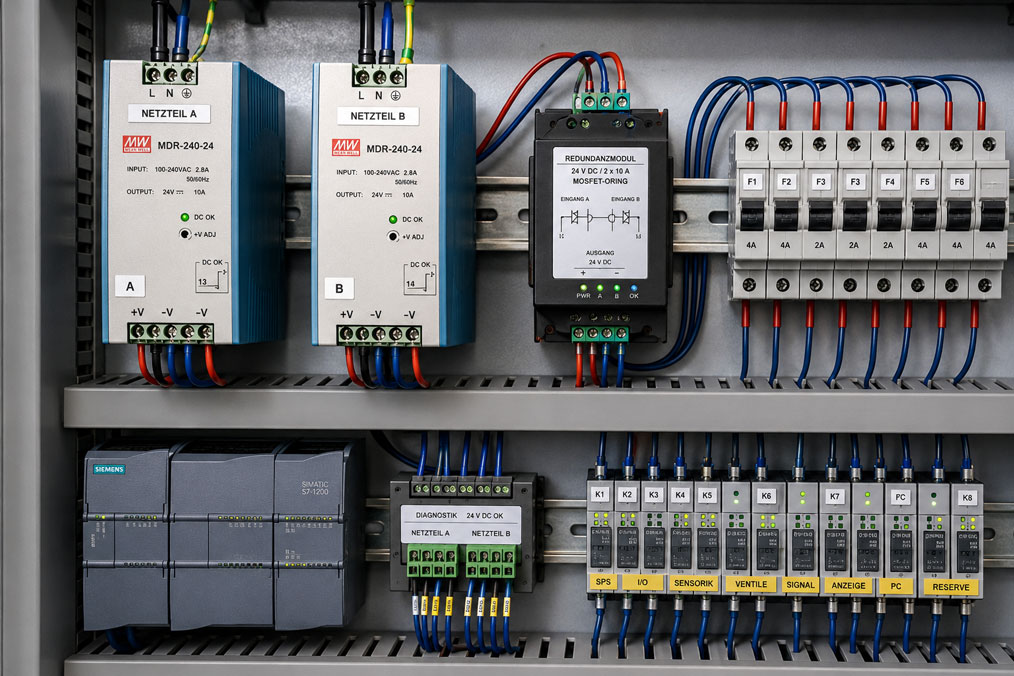
Two 24 V power supplies are installed next to each other in the control cabinet and their outputs are connected in parallel. Does this automatically provide the control system with a redundant power supply? Not necessarily.
Reliable redundancy is achieved only when the failure of one supply branch does not affect the common 24 V bus and the remaining branch can take over the entire required load. This requires suitable decoupling, sufficient power reserve, correctly dimensioned cables and fuses, and clear failure signalling.
Diagnostics are particularly important. If the common 24 V supply remains available when one power supply fails, the fault may go unnoticed during normal plant operation. The system continues to run but no longer has redundancy. If the second supply branch then also fails, the result is a complete loss of power.
Suitable components for industrial power supply systems can be found in the ICS category Power Supply. Power supplies for testing, commissioning and laboratory applications are grouped under Power Supplies and Laboratory Power Supplies.
Table of Contents
- What does a redundant 24 V power supply mean?
- Correctly distinguishing between 1+1 and N+1
- Why two power supplies connected in parallel are not automatically redundant
- Why is decoupling required?
- Comparing diode and MOSFET decoupling
- Correctly dimensioning power supplies
- Accounting for load sharing between the power supplies
- Avoiding common faults in the incoming supply
- Correctly planning fuses and short-circuit behaviour
- Accounting for cable sizing and voltage drop
- Clearly signalling the failure of each supply branch
- Preparing for maintenance during plant operation
- Do not confuse redundancy with a UPS
- Systematically testing the redundancy function
- Practical example of a 24 V 1+1 power supply
- Typical errors in redundant power supplies
- What should be included in the documentation?
- Which products and solutions are suitable?
- Conclusion
- Frequently asked questions
What does a redundant 24 V power supply mean?
Redundancy means that the failure of one intended supply branch does not result in the loss of the 24 V supply.
A simplified configuration consists of:
- Power Supply A,
- Power Supply B,
- decoupling of the two DC outputs,
- a common 24 V load bus,
- monitoring of both supply branches.
During normal operation, both power supplies can supply the load together. If one fails, the other must be capable of supplying the entire load required for safe continued operation.
However, redundancy planning must always consider the complete power supply chain. Two power supplies alone do not protect against, for example:
- failure of a common AC supply,
- tripping of a common upstream protective device,
- a short circuit on the common 24 V bus,
- failure of a common downstream distribution system,
- overtemperature of the entire control cabinet,
- faults caused by overvoltage or other common external influences.
Redundancy must therefore always be assessed in relation to the specific assumed fault.
Correctly distinguishing between 1+1 and N+1
1+1 redundancy
With a 1+1 power supply, each of the two power supplies is fundamentally capable of supplying the required load on its own.
Example:
- maximum plant load: 8 A,
- Power Supply A: 10 A,
- Power Supply B: 10 A.
During normal operation, both power supplies may each provide approximately 4 A. If one power supply fails, the remaining unit takes over the full 8 A.
The decisive point is:
For redundancy assessment, the system must not be calculated on the basis of 20 A of available total power.
In the event of a failure, only the 10 A capacity of the remaining power supply is still available in this example.
N+1 redundancy
In an N+1 architecture, several power supplies are used. N units are required to supply the maximum load. One additional power supply provides the reserve.
One example would be four 10 A power supplies for a load that can still be safely supplied by three units in the event of a failure.
N+1 systems require suitable parallel operation and load-sharing capability. They are frequently used for higher power levels where a single power supply capable of supplying the entire load would be impractical.
Why two power supplies connected in parallel are not automatically redundant
If the positive outputs of two power supplies are connected directly together without further evaluation, several problems can occur.
If Power Supply A has a slightly higher output voltage than Power Supply B, for example, A may take over a large proportion of the load. Equal current sharing does not occur automatically.
The behaviour in the event of a fault is even more critical. If one power supply develops an internal fault:
- current may flow back from the intact power supply into the defective output,
- the common output voltage may be pulled down,
- an internal short circuit may affect both supply branches.
A power supply approved for parallel operation may include load-sharing functions. However, this does not automatically replace the fault decoupling required for the intended redundancy concept.
The manufacturer’s specifications for the power supply used must therefore always be checked before direct parallel connection.
Why is decoupling required?
Decoupling ensures that both power sources can supply the load together while preventing a fault in one branch from affecting the other branch as far as possible.
In simplified form, the current flows as follows:
Power Supply A → Decoupling A → 24 V bus
Power Supply B → Decoupling B → 24 V bus
Reverse current from the bus into a switched-off or defective power supply is blocked.
This is particularly important when a power supply:
- is switched off,
- develops an internal short circuit,
- loses its output voltage,
- is removed from the system for maintenance.
Depending on the required availability level, it must also be checked whether a common dual-channel redundancy module itself represents a single point of failure.
For particularly rigorous redundancy concepts, two completely independent decoupling paths up to the load may therefore be required.
Comparing diode and MOSFET decoupling
Diode decoupling
The conventional solution uses diodes in the two output paths.
Advantages include:
- simple operating principle,
- passive decoupling,
- robust circuit design.
The disadvantage is the voltage drop across the diode. Depending on the component used and the current, this is typically several tenths of a volt.
The power loss can be calculated approximately as:
PV = UF × I
With a voltage drop of 0.4 V and a load of 10 A, for example:
PV = 0.4 V × 10 A = 4 W
This power is dissipated as heat inside the control cabinet.
MOSFET decoupling
Active redundancy modules frequently use MOSFETs as electronic ORing elements.
This can significantly reduce the voltage drop, resulting in:
- lower power loss,
- less heat generation,
- higher voltage at the load,
- advantages at high currents.
Modern active modules can additionally monitor the two inputs, the decoupling path and, in some cases, the current distribution.
Selection should therefore take into account not only the rated current but also voltage drop, power loss, diagnostic functions and fault behaviour.
Correctly dimensioning power supplies
The most important rule for a 1+1 power supply is:
One individual supply branch must be capable of supplying the maximum required load under the intended operating conditions.
The load includes more than just static rated currents.
The following must also be considered, for example:
- PLC and remote I/O,
- sensors and transmitters,
- gas detection instruments,
- relays and interface modules,
- solenoid valves,
- contactors,
- displays and industrial PCs,
- communication devices,
- inrush currents,
- future expansions.
Example:
| Load | Maximum current |
|---|---|
| PLC and I/O | 1.5 A |
| Measuring instruments and sensors | 1.2 A |
| Communication | 0.8 A |
| Valves and relays | 2.5 A |
| Other loads | 0.7 A |
| Total | 6.7 A |
A 1+1 system with two 5 A power supplies would not be redundant for this load. If one unit failed, the remaining power supply would have to provide 6.7 A.
Two appropriately dimensioned 10 A power supplies could, by contrast, provide a suitable basis, provided that temperature derating, inrush currents and the remaining components are also taken into account.
Accounting for load sharing between the power supplies
With two regulated power supplies operating in parallel, even a small difference in output voltage can determine the load distribution.
For example, the following values may be set:
- Power Supply A: 24.15 V,
- Power Supply B: 24.00 V.
Power Supply A may then provide significantly more current than Power Supply B.
For a 1+1 power supply, a perfect 50-to-50 load split is not necessarily required if each power supply can continuously supply the entire load on its own.
However, highly uneven loading has disadvantages:
- one power supply operates at a higher temperature continuously,
- components age at different rates,
- the actual functionality of the second branch may remain unnoticed,
- the transition during a failure may be less favourable.
Systems with active load sharing or current balancing therefore attempt to distribute the load evenly across the available power supplies.
Controlled load distribution is particularly important in N+1 concepts because several power supplies are required together to provide the total output power.
Avoiding common faults in the incoming supply
Two power supplies behind the same upstream fuse provide protection against an internal power supply failure, but not against failure of that common fuse.
For applications with high availability requirements, it should therefore be checked which components are still common to both branches.
Possible common fault sources include:
- common circuit breaker,
- common AC supply cable,
- common disconnect terminal,
- common surge protection device,
- common DC distribution system,
- common decoupling electronics,
- common ambient temperature.
A higher-availability concept can be implemented using two supply paths that are as independent as possible. How far this separation must extend depends on the required plant availability and, where applicable, the safety assessment.
A redundant 24 V power supply is therefore only as robust as the least well-protected common element in the system.
Correctly planning fuses and short-circuit behaviour
Each supply branch should be designed so that a fault in one branch does not switch off the other branch as far as possible.
This includes suitable protection for the individual power supplies and output cables.
The selection depends, among other things, on:
- maximum output current of the power supply,
- current-carrying capacity of the cable,
- permissible inrush current,
- short-circuit current of the power supply,
- tripping characteristic of the protective devices,
- DC switching capacity of the fuses or circuit breakers used.
Selectivity of the downstream load circuits is particularly important.
If, for example, a defective sensor causes a short circuit, ideally only the affected load branch should be switched off rather than the entire 24 V bus.
A second power supply does not help against a direct short circuit on a common, unprotected 24 V main bus. Both power supplies then feed the same fault.
Accounting for cable sizing and voltage drop
The cables must also be dimensioned for the redundancy case.
During normal operation with a total load of 8 A, for example, approximately 4 A may flow through each of the two branches. After one power supply fails, however, the complete 8 A may flow through only one remaining supply path.
This individual path must therefore be designed with regard to:
- conductor cross-section,
- terminal current rating,
- fuse,
- redundancy module,
- connectors
for the maximum fault condition.
The voltage drop must likewise not be calculated solely for normal operation.
In simplified form, the following applies to a DC cable:
ΔU = I × R
With long cable runs, the voltage at the load may drop more significantly after one power supply fails because the current in the remaining path increases.
The decisive factor is therefore the voltage directly at the most critical load, not merely the output voltage at the power supply.
Clearly signalling the failure of each supply branch
One of the most common weaknesses of redundant systems is insufficient diagnostics.
If Power Supply A fails, Power Supply B continues to maintain the common bus at approximately 24 V. Monitoring only the common output voltage may therefore fail to detect this fault completely.
The system then continues operating unnoticed in a non-redundant condition.
It is better to monitor both supply branches individually.
Suitable signals include, for example:
- DC OK relay contact of Power Supply A,
- DC OK relay contact of Power Supply B,
- diagnostic contact of the redundancy module,
- undervoltage monitoring before the decoupling stage,
- optionally current monitoring of both branches.
The PLC or control system should be able to distinguish at least the following states:
- both supply branches available,
- Supply Branch A failed,
- Supply Branch B failed,
- common 24 V supply outside the permissible range.
A single power supply failure should generate a maintenance alarm before a second fault results in plant shutdown.
Preparing for maintenance during plant operation
An important advantage of a 1+1 power supply is that a faulty branch can be serviced while the other branch continues to supply the load.
However, the installation must be prepared accordingly.
Useful measures include:
- clearly labelled Branches A and B,
- separate fuses or disconnecting devices,
- touch-safe terminals,
- clear DC OK indications,
- sufficient accessibility of the power supplies,
- a documented switching sequence.
Maintenance during operation does not mean that any power supply can simply be removed from the control cabinet while energised.
The supply branch being serviced must be safely isolated in accordance with the manufacturer’s instructions and electrical safety regulations. Only the connected plant remains supplied with 24 V via the second branch.
Do not confuse redundancy with a UPS
A redundant power supply and an uninterruptible power supply solve different problems.
| System | Primarily protects against |
|---|---|
| 1+1 redundancy | Failure of one power supply or supply branch |
| UPS or buffer module | Failure of the energy source for a defined bridging period |
If both redundant power supplies are supplied from the same AC source, both units fail simultaneously in the event of a complete mains failure.
For particularly critical loads, a combination of:
- redundant power supplies,
- independent incoming supplies,
- DC UPS or buffer storage
may therefore be required.
The appropriate architecture depends on the required backup time and the fault scenarios being considered.
Systematically testing the redundancy function
A redundant system should not only be wired correctly but also tested under realistic load conditions.
A useful functional test includes:
- Check normal operation: Record the output voltage and currents of both supply branches.
- Check diagnostics: Both DC OK or status signals must be present correctly.
- Switch off Branch A in a controlled manner: Power Supply B must take over the complete load without an unacceptable voltage drop.
- Check the failure indication: The failure of Branch A must be clearly reported.
- Switch Branch A back on: Verify the return to redundant operation.
- Switch off Branch B: Repeat the test in the opposite direction.
- Check maximum load: Verify redundancy at the highest intended operating current.
- Check start-up conditions: Take account of inrush currents from PLCs, valves, industrial PCs and other loads.
- Measure the voltage at the load: Do not check only directly at the power supply.
- Check the temperature: Inspect power supplies, redundancy modules, terminals and cables under load.
A short circuit should not be deliberately created simply to test the redundancy. Short-circuit and protection behaviour should be assessed using manufacturer data and safe test procedures intended for this purpose.
Practical example of a 24 V 1+1 power supply
A gas detection and process monitoring system requires 5.5 A during normal operation. Under the most demanding operating condition, including relays and signalling devices, 7.2 A is expected.
Two 24 V power supplies rated at 10 A each are provided.
The configuration is:
AC Branch A → Power Supply A → Fuse → Decoupling A → 24 V bus
AC Branch B → Power Supply B → Fuse → Decoupling B → 24 V bus
The loads are then supplied via separately protected 24 V outgoing circuits.
During normal operation, both power supplies share the load approximately equally.
| Operating condition | Power Supply A | Power Supply B | 24 V load |
|---|---|---|---|
| Normal operation | approx. 3.6 A | approx. 3.6 A | 7.2 A |
| Power Supply A failed | 0 A | 7.2 A | 7.2 A |
| Power Supply B failed | 7.2 A | 0 A | 7.2 A |
The DC OK contacts of both power supplies are connected separately to the PLC.
When Power Supply A is switched off, the output voltage remains within the permissible range for the loads. At the same time, the control system generates the message:
24 V supply Branch A failed redundancy unavailable
The plant continues to operate, but maintenance personnel immediately recognise that one additional fault could now result in a complete loss of supply.
This combination of continued operation and diagnostics is what turns two power supplies into a practical redundancy concept.
Typical errors in redundant power supplies
| Error | Possible consequence | Suitable corrective action |
|---|---|---|
| Two power supplies connected in parallel without decoupling | Reverse current or mutual interaction in the event of a fault | Provide suitable redundancy or ORing decoupling |
| Each power supply sized for only half the total load | Remaining power supply is overloaded after a failure | For 1+1, size each branch for the entire required load |
| Only the common 24 V voltage is monitored | Failure of one power supply remains undetected | Monitor both supply branches separately |
| Both power supplies connected behind the same fuse | Tripping of the protective device switches off both branches | Reduce common fault sources according to the availability requirement |
| Cables sized only for half the normal current | Overloading of the remaining path in the event of a failure | Size every relevant path for its maximum fault current |
| Redundancy module undersized | Overload or excessive voltage drop | Check channel current and total output current |
| Load sharing not checked | One power supply operates permanently close to full load | Check output voltages and load distribution |
| Common 24 V output not selectively protected | A fault in one load can switch off the entire supply | Protect load circuits separately |
| Redundancy confused with UPS functionality | Both power supplies fail simultaneously during a mains outage | Add a UPS or energy storage system if backup is required |
| Redundancy never tested under load | Fault is only discovered during an actual failure | Regularly test the failure of each branch individually |
What should be included in the documentation?
For a traceable 24 V power supply system, at least the following should be documented:
- power supply concept 1+1 or N+1,
- power supply type and rated output current,
- maximum plant load,
- inrush and peak currents considered,
- temperature derating of the power supplies,
- type of decoupling,
- rated current of the redundancy module,
- voltage drop across the decoupling path,
- AC supply for Branches A and B,
- fuses or protective devices,
- conductor cross-sections,
- DC distribution,
- DC OK and fault signalling contacts,
- alarm text in the PLC or control system,
- measured currents during normal operation,
- voltage at the most critical load,
- result of the failure test for Branch A,
- result of the failure test for Branch B,
- date of the most recent functional test.
The circuit diagram should show the two supply paths clearly separated. This makes it immediately apparent during later maintenance which components belong to Branch A and which belong to Branch B.
Which products and solutions are suitable?
Industrial 24 V power supplies
The ICS category Power Supply includes various power supplies, DC-DC converters, chargers and other components for industrial power supply systems.
When selecting components for a redundant 24 V power supply, the following should be considered in particular:
- 24 V output voltage,
- sufficient rated current from one individual supply branch,
- permissible ambient temperature and derating,
- overload and short-circuit behaviour,
- adjustable output voltage,
- DC OK or status contact,
- approval for the planned parallel or redundant operation.
ISDR-120 industrial power supply
The ISDR-120 series is a compact industrial DIN-rail power supply with an output power of 120 W.
The 24 V version provides up to 5 A and has an integrated DC OK relay contact. This allows the operating status of the power supply to be monitored via a PLC or control system.
Additional features include:
- 24 V DC output voltage for the corresponding version,
- 5 A output current at 24 V,
- adjustable output voltage,
- protection against short circuit, overload, overvoltage and overtemperature,
- mounting on a TS-35 DIN rail,
- DC OK relay contact.
Whether a specific power supply can be used in a particular redundant architecture, and which type of decoupling is required, must be checked on the basis of the manufacturer’s specifications and the complete power supply concept.
Redundancy modules
A redundancy module forms the electrical isolation point between the two power supply outputs and the common load.
The following are particularly important when selecting a module:
- input voltage range,
- permissible current per input,
- permissible total current,
- voltage drop,
- diode or MOSFET technology,
- reverse-current blocking,
- diagnostic contacts,
- monitoring of the decoupling path.
For particularly high availability requirements, it should also be checked whether the decoupling stage itself must be implemented redundantly.
Power supplies and laboratory power supplies
The Power Supplies and Laboratory Power Supplies are particularly suitable for development, testing, commissioning and simulation of 24 V loads.
They can be used, for example, to:
- determine load currents,
- test undervoltage behaviour,
- measure the current consumption of individual assemblies,
- test power supply concepts before final integration into the control cabinet.
However, a laboratory power supply does not automatically replace a redundant industrial power supply designed for permanent control cabinet operation.
ICS Schneider Messtechnik provides support in designing the power supply, output capacity, redundancy concept, decoupling, monitoring and suitable components for industrial measurement, control and monitoring systems.
Conclusion
Two 24 V power supplies connected in parallel do not yet constitute a complete redundant power supply.
In a 1+1 architecture, each power supply must be capable of supplying the maximum required plant load on its own. Suitable decoupling prevents a failed supply branch from feeding back into or pulling down the still-functioning branch.
Diode modules provide a simple decoupling principle but cause a voltage drop and corresponding power loss. Active MOSFET redundancy modules can significantly reduce these losses and provide additional diagnostic functions.
The entire power supply chain must be considered. Common AC fuses, distribution systems, cables or a common decoupling module can limit the actual redundancy.
Failure signalling is particularly important. Because the common 24 V supply can remain available after one power supply fails, both supply branches must be monitored separately.
Cables, fuses and terminals must also be dimensioned for the fault condition in which one individual branch supplies the complete load.
A redundant power supply is also not a substitute for a UPS. If a complete loss of the energy source must also be bridged, a suitable buffer or UPS concept must be added.
The design is complete only after a functional test under actual load. During this test, both supply branches are switched off one after the other and it is verified that voltage, load transfer and failure signalling operate as intended.
Frequently asked questions about redundant 24 V power supplies
Can I simply connect two 24 V power supplies in parallel?
Only if the devices are suitable for this and the intended system concept permits it. For true redundancy, defined decoupling is normally required so that a faulty power supply does not affect the intact supply branch.
What does 1+1 redundancy mean?
One power supply can provide the complete required load. A second equivalent power supply is additionally available or operates in parallel. If one unit fails, the other takes over the full load.
What does N+1 mean?
N power supplies are required to provide the total load. One additional power supply provides the reserve. If one unit fails, the remaining N power supplies must still be capable of supplying the complete load.
Why do I need a redundancy module?
It electrically decouples the power supplies from one another and, in particular, prevents unwanted reverse current into a failed supply branch.
Which is better, diode or MOSFET?
Diode decoupling is simple and robust but causes a comparatively higher voltage drop. Active MOSFET decoupling normally has lower losses and can provide additional monitoring functions.
Do both power supplies have to provide exactly the same current?
Not necessarily in a conventional 1+1 system. However, each power supply must be capable of supplying the complete load. The most even load distribution possible reduces thermal stress and allows more uniform ageing.
Why is monitoring the 24 V bus alone insufficient?
Because if one power supply fails, the second unit continues to maintain the voltage. Without separate diagnostics, the plant may operate for a long time without redundancy without anyone noticing.
Do both power supplies require their own AC fuse?
For high availability requirements, common fault sources should be reduced as far as necessary. A common upstream fuse can switch off both power supplies simultaneously and therefore limit the effectiveness of the redundancy.
Can a redundant power supply system handle a short circuit on the 24 V bus?
No. If the short circuit is located on a common output path that is not selectively isolated, both power supplies feed the same fault. Suitable distribution and protection of the individual load circuits are therefore important.
Is a redundant power supply also a UPS?
No. Redundancy primarily protects against the failure of one supply branch. A UPS, by contrast, bridges the failure of the energy source for a defined period of time.
How do I test the redundancy?
Under a defined load, one supply branch is first switched off in a controlled manner. The 24 V supply must remain available and a clear failure message must appear. The same test is then performed with the second branch.
Can I replace a power supply while the system is operating?
With a correctly designed 1+1 system, the connected plant can continue operating from the remaining power supply. However, the power supply being replaced must itself be safely isolated in accordance with the manufacturer’s instructions and electrical safety regulations.