


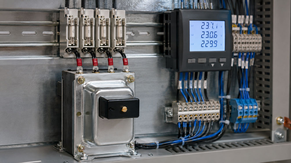
A voltage transformer with a ratio of 400 V / 100 V initially seems simple to select: 400 V is applied on the primary side and the measuring instrument receives 100 V on the secondary side. In practice, however, this consideration alone is not sufficient. Selecting an unsuitable burden, configuring an incorrect transformation ratio or having an excessive voltage drop in the secondary wiring can result in an otherwise precise voltage transformer no longer providing sufficiently accurate measurement within the complete measuring circuit.
There are also questions concerning protection and connection. Should the primary side be separately fused? Which fuse should be installed on the secondary side? May the secondary side of a voltage transformer be short-circuited? Does one secondary terminal need to be grounded? And how many VA does the transformer actually need to provide?
It is also particularly important to distinguish between a voltage transformer for measurement and protection applications and a conventional transformer used for power supply. An instrument voltage transformer is intended to reproduce a primary voltage as accurately and phase-correctly as possible at a defined secondary value. It is not intended to supply arbitrary control devices, relays or other loads with power.
For correct selection of a voltage transformer, primary voltage, secondary voltage, connection type, transformation ratio, accuracy class, actual burden, wiring losses, protection and the downstream measuring instrument must be considered together.
Suitable devices are available from ICS Schneider under Voltage Transformers for Low-Voltage Measuring Circuits and generally under Measuring Instruments for Plant and Control Panel Construction.
For measurement and protection applications, for example, the BTV 6 Voltage Transformer and BTV 10 Voltage Transformer are available. Depending on the version, primary voltages up to 690 V can be transformed to standardized secondary voltages such as 100 V or 100/√3 V.
Table of Contents
- What is a voltage transformer for measuring circuits?
- Distinguishing between an instrument voltage transformer and a power supply transformer
- Correctly calculate the transformation ratio
- Distinguishing between phase-to-phase and phase-to-neutral
- Correctly configure the transformation ratio in the measuring instrument
- What does the burden of a voltage transformer mean?
- Calculate the total burden of the measuring circuit
- Why a higher VA rating is not automatically better
- Consider wiring resistance and voltage drop
- Correctly interpret the accuracy class
- Distinguishing between measuring and protection windings or measuring and protection classes
- Correctly protect the primary side
- Correctly protect the secondary side
- Why a voltage transformer must not be short-circuited on the secondary side
- Do not confuse voltage transformers with current transformers
- Secondary circuit and grounding concept
- Operate several measuring instruments from one voltage transformer
- Use voltage transformers in three-phase systems
- When direct voltage measurement is more suitable
- Consider mains frequency and special frequencies
- Correctly evaluate the rated voltage factor
- Systematically commission a voltage transformer
- Typical faults in voltage transformer measuring circuits
- Practical example: 400 V to 100 V for a panel meter
- Systematically select a voltage transformer
- Suitable voltage transformers at ICS Schneider
- Conclusion
- FAQ
What is a voltage transformer for measuring circuits?
A voltage transformer is an instrument transformer that proportionally transforms an AC voltage to a defined lower voltage value.
The simplified measuring chain is:
mains voltage → voltage transformer → secondary voltage → measuring instrument / energy meter / protection device
Typical secondary voltages of instrument voltage transformers include:
100 V
or for a phase-to-neutral measurement:
100 / √3 V ≈ 57.7 V
The main advantage is that the downstream measuring instrument does not have to be designed directly for the full mains voltage and the measuring circuit can be galvanically isolated from the primary circuit.
Typical applications
- voltage indication in control panels,
- multifunction measuring instruments,
- energy meters,
- power network monitoring,
- measuring transducers,
- protection relays,
- synchronization and voltage comparison.
Distinguishing between an instrument voltage transformer and a power supply transformer
A voltage transformer used for measurement purposes is not the same as a transformer used to supply control circuits.
Instrument voltage transformer
The primary task is:
transfer the primary voltage as accurately and proportionally as possible
The following are therefore particularly relevant:
- ratio error,
- phase displacement error,
- accuracy class,
- defined burden,
- measurement or protection requirements.
Power supply transformer
With a control or power supply transformer, on the other hand, supplying a load is the primary objective.
Typical loads include:
- relays,
- contactors,
- controllers,
- valves,
- auxiliary circuits.
Here, output power, voltage regulation, inrush current and thermal load capacity are among the important parameters.
A precise instrument voltage transformer should therefore not be used as a general auxiliary power supply for additional loads.
For such applications, ICS Schneider offers separate solutions under Power Supplies, Transformers and Converters.
Correctly calculate the transformation ratio
The transformation ratio is calculated from the rated primary and secondary voltages.
In simplified form:
kU = Uprim / Usec
Example
A voltage transformer has:
Uprim = 400 V
and:
Usec = 100 V
This results in:
kU = 400 V / 100 V = 4
If the downstream measuring instrument measures the following on the secondary side:
97.5 V
this corresponds on the primary side to:
97.5 V × 4 = 390 V
The transformation ratio is part of the complete measuring chain
The voltage transformer initially only provides the secondary voltage.
The measuring instrument must then know which primary/secondary ratio is being used.
If, for example, the instrument is incorrectly configured for:
500 / 100 V
instead of:
400 / 100 V
the measuring instrument will display a proportionally incorrect primary value.
Distinguishing between phase-to-phase and phase-to-neutral
In three-phase systems, it must be clarified which voltage is actually to be measured.
Phase-to-phase
In a typical European 400 V system, the line-to-line voltage is:
U L-L = 400 V
A voltage transformer can, for example, transform:
400 V → 100 V
.
Phase-to-neutral
In the same system, the voltage between a phase conductor and neutral is approximately:
U L-N = 400 V / √3 ≈ 230 V
A suitable transformer can, for example, be designed with the ratio:
400 / √3 V → 100 / √3 V
.
The secondary voltage with respect to the neutral point is then:
approx. 57.7 V
The transformation ratio remains the same
With:
400 / √3 V → 100 / √3 V
the ratio is also:
kU = 4
However, the connection type must match the network and the downstream measuring instrument.
Correctly configure the transformation ratio in the measuring instrument
Many digital panel meters, energy meters and multifunction measuring instruments can be operated directly with a voltage transformer.
Configuration parameters frequently include values such as:
VT Primary
and:
VT Secondary
or:
Voltage Transformer Ratio
.
Example
Transformer:
600 V / 100 V
Measuring instrument:
VT Primary = 600 V
VT Secondary = 100 V
Transformation ratio:
6
Particularly important for power and energy measurements
An incorrectly configured voltage does not only affect the displayed voltage.
Calculated quantities can also be affected, for example:
- active power,
- reactive power,
- apparent power,
- active energy,
- reactive energy.
If current transformers are also used:
voltage transformer ratio × current transformer ratio
must be correctly taken into account when scaling the complete power measurement.
What does the burden of a voltage transformer mean?
The burden describes the electrical load on the secondary side of the voltage transformer.
It is normally specified in:
VA
.
Connected measuring instruments consume a small amount of power on the secondary side.
Together, these loads form the burden of the transformer.
Typical secondary loads include
- voltmeters,
- multifunction measuring instruments,
- energy meters,
- measuring transducers,
- protection relays,
- monitoring relays.
The relevant information in the data sheet of the downstream device may, for example, be specified as:
Voltage input: power consumption 0.5 VA
If several devices are connected in parallel, their burdens generally add together.
Calculate the total burden of the measuring circuit
For an initial design, the total burden can be determined approximately from the connected devices.
Example:
| Load | Burden |
|---|---|
| Digital voltmeter | 0.5 VA |
| Energy meter | 0.5 VA |
| Network monitoring relay | 1.0 VA |
| Measuring transducer | 0.5 VA |
This results in:
Stotal = 0.5 + 0.5 + 1.0 + 0.5 VA
Stotal = 2.5 VA
Losses or additional loads in the secondary circuit may also have to be added.
A 6 VA voltage transformer therefore has sufficient rated burden – but:
It is not sufficient simply to verify:
2.5 VA < 6 VA
The burden range over which the manufacturer guarantees the required accuracy class must also be checked.
Why a higher VA rating is not automatically better
With power supply transformers, intentional power reserve is often provided.
With a precision voltage transformer, however, this principle cannot be applied without limitation.
A strongly oversized voltage transformer can be disadvantageous from a measurement perspective
The accuracy specifications of an instrument voltage transformer apply to defined burdens or burden ranges.
If, for example, only a very small electronic measuring instrument burden is connected even though the transformer is designed for a considerably higher rated burden, the actually achievable measurement accuracy may change.
Modern digital measuring instruments often have a comparatively high input impedance and therefore require very little power.
Selecting according to the principle “100 VA is safer than 10 VA” is therefore not automatically correct for instrument voltage transformers.
A rated burden should be selected that matches the actual measuring circuit and the guaranteed accuracy range of the transformer.
Consider wiring resistance and voltage drop
The accuracy of a voltage transformer is specified at its secondary terminals.
However, the measuring instrument may be located several meters away within the installation.
Between the transformer and measuring instrument there may be:
- cables,
- fuse elements,
- terminals,
- disconnect terminals,
- plug connections.
Each of these components can cause an additional voltage drop.
Wiring loss
For an ohmic conductor, the following simplified equations apply:
Uloss = Isec × Rwiring
and:
Pwiring = Isec² × Rwiring
In a 100 V measuring circuit, currents are often small
A burden of:
5 VA
at:
100 V
corresponds approximately to:
I = 5 VA / 100 V = 0.05 A
or:
50 mA
Nevertheless, long cable runs can become relevant for high-accuracy measurements.
Particularly important for precision measurements
The transformer may comply with its accuracy class at the secondary terminals while the more distant measuring instrument already has a larger overall error due to the additional voltage drop.
The accuracy of the voltage transformer is therefore not automatically the accuracy of the complete measuring circuit.
Correctly interpret the accuracy class
Instrument voltage transformers are specified according to defined accuracy classes.
Typical classes for measurement purposes include:
Class 0.5
or:
Class 1
The class does not simply describe a fixed error at any voltage and any burden.
The permissible ratio and phase errors apply under the operating conditions defined in the relevant standard and data sheet.
For selection, this means
The following must be considered together:
- accuracy class,
- primary voltage,
- burden,
- frequency,
- intended use.
A simple voltage indication may require a different level of accuracy than an energy measurement or a protection function.
Distinguishing between measuring and protection windings or measuring and protection classes
Voltage transformers can be designed for measurement applications and for protection applications.
Measurement
Here, the priority is the most accurate possible transfer within the normal operating range.
Typical accuracy classes of the BTV series offered by ICS Schneider include:
0.5
and:
1
Protection
For protection devices, it is additionally important that the voltage ratio remains sufficiently defined within the voltage ranges relevant to the protection function.
Special protection classes are used for this purpose, for example:
3P
.
A protection class should therefore not simply be interpreted as a “less accurate measuring class”.
It describes a different function within the electrical protection system.
Correctly protect the primary side
The primary side of a voltage transformer is directly connected to the power network being measured.
The primary wiring must therefore be designed according to the mains voltage, prospective short-circuit current and the protection concept used.
Suitable primary protection can protect, among other things
- the connecting cable,
- the measuring branch,
- the voltage transformer in the event of internal faults,
- downstream parts of the installation.
The specific fuse rating cannot be determined solely from the VA burden of the measuring circuit.
The following must be considered, among other things:
- manufacturer specifications for the transformer,
- network configuration,
- rated voltage,
- available short-circuit current,
- conductor cross-section,
- selectivity,
- applicable installation and product standards.
A general statement such as “every voltage transformer is fused with 2 A on the primary side” would therefore not be technically correct.
Correctly protect the secondary side
The secondary circuit of a voltage transformer can also carry high currents in the event of a short circuit.
Suitable secondary protection protects in particular:
- measuring cables,
- terminals,
- measuring instruments,
- other connected circuits.
Several measuring circuits
If several devices or functional groups are supplied by one transformer, separate fusing or a disconnect facility for individual measuring branches may be useful.
This makes it possible, for example, to service one measuring instrument without unnecessarily disconnecting the entire secondary circuit.
Fuse and accuracy
A fuse also has electrical resistance.
For high-accuracy measurements, the possible voltage drop within the complete secondary circuit must therefore be taken into account.
The fuse should also be selected so that:
- the conductor is protected,
- the required disconnection condition is achieved,
- unnecessary voltage drops are avoided,
- the measurement function is not unintentionally affected.
Why a voltage transformer must not be short-circuited on the secondary side
A voltage transformer behaves fundamentally differently from a current transformer with regard to its secondary circuit.
With a voltage transformer
the secondary circuit is intended to provide a defined voltage.
A short circuit means:
very low load impedance → very high secondary current
This can cause:
- thermal overload of the windings,
- fuses to operate,
- cables to become overloaded,
- damage to the voltage transformer.
The secondary side of a voltage transformer must therefore not be intentionally short-circuited.
Do not confuse voltage transformers with current transformers
This difference is particularly safety-relevant during maintenance work.
| Characteristic | Voltage transformer | Current transformer |
|---|---|---|
| Secondary operation | approximately a voltage source | approximately a current source |
| Short-circuit secondary | not permissible | common or necessary during maintenance when performed correctly |
| Open secondary circuit | open-circuit operation is generally possible | dangerous and must be avoided while primary current is flowing |
| Loads | connected in parallel | connected in series in the secondary current circuit |
The commonly known rule “never open the secondary circuit of an instrument transformer” applies to current transformers and must not be transferred to voltage transformers.
Conversely, the short-circuit link used with current transformers must never be applied without consideration to a voltage transformer measuring circuit.
Secondary circuit and grounding concept
A galvanically isolated voltage transformer initially creates a secondary circuit whose potential relative to ground must be defined by the system design.
Depending on the application, one point on the secondary side may be connected to ground or to a defined reference potential.
Objectives may include
- a defined secondary potential,
- avoiding a floating measuring circuit,
- protection in the event of insulation faults between the primary and secondary circuits,
- a clear reference for connected devices.
However:
Whether and where grounding is provided depends on:
- network configuration,
- protection concept,
- device design,
- plant standard,
- applicable regulations.
The secondary circuit should not be grounded at several unplanned points, as this can create additional current paths and measurement errors.
An intentionally grounded connection must also not be unintentionally interrupted by an incorrectly positioned fuse or disconnecting device.
Operate several measuring instruments from one voltage transformer
Voltage inputs are generally connected in parallel to the secondary circuit.
Example:
100 V voltage transformer → voltmeter + energy meter + measuring transducer
The total burden increases with every additional device
After extending the circuit, it must therefore be checked that:
Stotal ≤ permissible transformer burden for the required accuracy class
Typical retrofit error
A system originally contains only an analog voltmeter.
Later, the following are additionally installed:
- energy meter,
- network monitoring relay,
- measuring transducer.
Electrically, all devices function.
Nevertheless, the original voltage transformer design may no longer match the new total burden.
After every significant modification, the measuring chain should therefore be reassessed.
Use voltage transformers in three-phase systems
For three-phase voltage measurement, the required number and connection arrangement of the voltage transformers depends on the network configuration and measuring task.
Possible concepts include, for example:
- three voltage transformers between phase conductors and neutral point,
- voltage transformers connected between phase conductors,
- special circuits for three-wire systems.
The downstream measuring instrument is decisive
A multifunction measuring instrument can, for example, be configured differently for:
- 3P3W,
- 3P4W,
- measurement via voltage transformers.
An incorrect network configuration can result in:
- incorrect voltages,
- incorrect power values,
- incorrect energy readings
even when the voltage transformers themselves are correctly sized.
When direct voltage measurement is more suitable
A voltage transformer is not automatically required in low-voltage installations.
Many modern panel and multifunction measuring instruments can measure mains voltages directly.
Direct measurement can be suitable when
- the mains voltage is within the permissible measuring range,
- the required insulation coordination is provided,
- no additional galvanic isolation is required,
- the measuring instrument is designed for the relevant measurement category and application.
A voltage transformer can be useful when
- the measuring instrument only has a standardized transformer input,
- galvanic isolation is required,
- several devices are to be supplied with the same standardized secondary voltage,
- a defined measuring or protection class is required,
- the primary voltage cannot be processed directly by the measuring instrument.
For a new installation, it should therefore first be checked whether a voltage transformer is actually required at all.
Consider mains frequency and special frequencies
Inductive voltage transformers are designed for a defined frequency range.
For the BTV 6 and BTV 10, ICS Schneider specifies, for example:
Rated frequency 50 Hz
and an operating range of:
47 … 63 Hz
Optional versions for:
400 Hz
are available with a defined burden for this frequency.
Why this is important
The magnetic characteristics of the transformer depend on frequency and voltage.
A transformer designed for a 50 Hz network must therefore not be used without verification for arbitrary:
- variable frequency drive outputs,
- 400 Hz onboard power systems,
- variable frequencies.
In particular, the PWM output of a variable frequency drive is not a conventional sinusoidal mains voltage.
Correctly evaluate the rated voltage factor
In addition to the rated voltage, voltage transformers specify a rated voltage factor.
This describes the increased primary voltage that the transformer can withstand under defined conditions or must reproduce within its intended function.
For the BTV 6 and BTV 10, ICS Schneider specifies, for example
for continuous operation:
1.2 × Upr
and for certain phase-to-neutral applications for a limited period:
1.9 × Upr for 8 hours
.
This value must not be confused with a freely usable continuous overload reserve.
The permissible application depends on the connection type and manufacturer specifications.
Systematically commission a voltage transformer
- Determine the network configuration: Define single-phase, 3-wire or 4-wire system.
- Define the measured quantity: Determine whether phase-to-phase or phase-to-neutral voltage is to be measured.
- Check the primary voltage: Record rated voltage and possible overvoltages.
- Select the secondary voltage: Consider the input of the downstream measuring instrument.
- Calculate the transformation ratio: Document the primary/secondary ratio.
- Define the accuracy requirement: Distinguish between indication, energy measurement and protection.
- Determine device burdens: Add the VA ratings of all connected voltage inputs.
- Check the cable route: Consider conductor cross-section, length and possible voltage drops.
- Select the transformer burden: Compare the actual load with the guaranteed accuracy range.
- Define primary protection: Select the fuse or protective device to suit the installation.
- Define secondary protection: Protect cables and connected devices against short circuits.
- Check the grounding concept: Clearly define the secondary reference potential.
- Check the wiring: Do not interchange primary and secondary terminals.
- Configure the measuring instrument: Correctly enter primary and secondary voltage.
- Assign phases: For three-phase measurements, clearly assign voltage channels to L1, L2 and L3.
- Measure the secondary voltage: Perform a plausibility check before commissioning.
- Compare the primary value: Verify the transformation ratio using a reference measurement.
- Document the measuring circuit: Record transformer data, fuses, burden, transformation ratio and connected devices.
Typical faults in voltage transformer measuring circuits
| Observation | Possible cause | Recommended check |
|---|---|---|
| Displayed voltage is incorrect by an exact constant factor | incorrect transformation ratio configured | check VT Primary and VT Secondary |
| 400 V network is displayed as approximately 100 V | measuring instrument displays secondary value without scaling | activate the transformer ratio in the measuring instrument |
| Voltage decreases when several devices are connected | burden or voltage drop in the secondary circuit is too high | check total burden and cable route |
| Measured value is correct at the transformer but not at the remote measuring instrument | voltage drop in cable, fuse or terminals | compare voltage directly at both measuring points |
| Secondary fuse operates | short circuit or wiring error | de-energize and check secondary circuit for faults |
| Primary fuse repeatedly operates | possible transformer fault or incorrect protection sizing | check transformer and protection concept |
| Transformer becomes unusually warm | possible overload, incorrect voltage or incorrect frequency | check primary voltage, frequency and burden |
| Only one phase shows incorrect values | incorrect phase assignment or defective individual fuse | check L1/L2/L3 assignment and fuses |
| Power measurement is incorrect although voltages appear plausible | voltage and current channels assigned to different phases | check phase sequence and measuring channel assignment |
| Measured value fluctuates after the measuring circuit has been extended | additional burden or contact problem | recalculate the total burden |
| Transformer was intentionally short-circuited on the secondary side | confusion with a current transformer | remove the short circuit immediately and check the transformer |
| Measurement shows an offset relative to ground | unclear or multiple grounding arrangement | check secondary reference and grounding points |
Practical example: 400 V to 100 V for a panel meter
In a machine, the line-to-line voltage of a 400 V network is to be monitored using a panel meter.
The measuring instrument is designed for a voltage transformer input of:
100 V AC
.
Step 1: Transformation ratio
The selected ratio is:
400 V / 100 V
Therefore:
kU = 4
Step 2: Burden of the measuring instrument
Assume that the voltage input requires:
0.5 VA
In addition, a measuring transducer with:
1 VA
is connected.
Total:
S = 1.5 VA
Step 3: Select the transformer
A transformer with a rated burden above the actual load and suitable for the required accuracy class is selected.
The highest possible VA rating is not simply selected. Instead, the burden range specified for the required class is checked.
Step 4: Wiring
The primary side is connected to the two phase conductors in accordance with the system and protection concept.
On the secondary side, the measuring instrument and measuring transducer are connected in parallel.
Step 5: Configuration
The measuring instrument is configured as follows:
Primary Voltage = 400 V
Secondary Voltage = 100 V
Step 6: Plausibility check
With an actual mains voltage of:
404 V
the secondary voltage should be approximately:
101 V
.
The panel meter scales this value back to approximately:
404 V
Result
The transformer is not selected only according to 400/100 V. Only the combination of transformation ratio, burden, accuracy class, wiring, protection and configuration creates a correctly functioning measuring circuit.
Systematically select a voltage transformer
- Determine the primary network: Record rated voltage, network configuration and frequency.
- Define the connection type: Specify phase-to-phase or phase-to-neutral.
- Define the secondary voltage: Select, for example, 100 V or 100/√3 V to suit the measuring instrument.
- Determine the transformation ratio: Clearly document the primary and secondary values.
- Define the measurement or protection task: Select the required accuracy class.
- Determine the burden of each device: Check the data sheets of the voltage inputs.
- Calculate the total burden: Consider all loads connected in parallel.
- Check the accuracy range: Do not consider only the maximum VA rating of the transformer.
- Consider wiring losses: Particularly with long secondary wiring and high accuracy requirements.
- Check the frequency: Consider 50/60 Hz or special frequencies.
- Check the rated voltage factor: Select it to match the network and connection type.
- Design primary protection: Size the protective device according to the complete installation concept.
- Design secondary protection: Protect measuring cables and connected devices.
- Define grounding: Clearly integrate the secondary circuit into the protection concept.
- Configure the measuring instrument: Correctly set the transformer ratio and network configuration.
- Realistically plan future expansion: Allow for future devices without unnecessarily oversizing the transformer.
- Perform a commissioning measurement: Compare the primary and secondary values.
Suitable voltage transformers at ICS Schneider
ICS Schneider offers voltage transformers for measurement and protection applications in low-voltage systems in different power and accuracy classes.
BTV 3 – for smaller measuring burdens
The BTV 3 Voltage Transformer is designed for AC voltage measuring circuits.
ICS Schneider specifies, among other things:
- different primary voltages for low-voltage systems,
- secondary voltages of 100 V or 100/√3 V and other versions,
- measuring version Class 1,
- burdens up to 6 VA for the corresponding phase-to-phase version or 3 VA for the corresponding phase-to-neutral version.
The BTV 3 is therefore particularly suitable for measuring circuits with comparatively low power consumption.
BTV 6 – measurement and protection
The BTV 6 is designed for measurement and protection applications.
ICS Schneider specifies, among other things:
- phase-to-phase primary voltage
100 … 690 V, - secondary voltage
100 V, - phase-to-neutral versions
100/√3 … 690/√3 V, - secondary voltage
100/√3 V, - accuracy classes 0.5 and 1 for measurement,
- protection class 3P,
- rated frequency 50 Hz,
- operating frequency
47 … 63 Hz, - optional 400 Hz with defined burden,
- rated voltage factor
1.2 × Uprin continuous operation.
For accuracy class 0.5, ICS specifies for corresponding versions, for example:
6 VA for phase-to-phase
or:
3 VA for phase-to-neutral
.
BTV 10 – higher measuring burden
The BTV 10 is also available in versions for measurement and protection applications.
Specifications include, among other things:
- primary voltages up to 690 V,
- 100 V or 100/√3 V secondary,
- accuracy classes 0.5 and 1,
- protection class 3P,
- 50 Hz version,
- operating range 47 … 63 Hz,
- optional 400 Hz,
- rated voltage factor 1.2 in continuous operation.
Compared with smaller versions, the BTV 10 can be suitable for measuring chains in which several or higher-power secondary loads are connected.
Additional BTV versions
For increasing burdens, the product group also includes:
- BTV 20,
- BTV 50,
- BTV 100
.
However, selection should not be based solely on the maximum available VA rating.
The decisive factor is always the combination of required accuracy class and actual burden of the measurement or protection circuit.
An overview is available under Voltage Transformers at ICS Schneider.
Conclusion
Voltage transformers enable galvanically isolated and standardized voltage measurement in electrical installations. For reliable measurement, however, it is not sufficient to select only the primary and secondary voltages.
The transformation ratio determines scaling
With a transformer from 400 V to 100 V, the ratio is 4. This value must also be correctly configured in the downstream measuring instrument.
The connection type must match the network
Phase-to-phase and phase-to-neutral applications use different rated voltages. Values such as 100 V and 100/√3 V must not be confused.
The burden also affects measurement accuracy
All connected measuring instruments load the secondary circuit. At the same time, an unnecessarily oversized voltage transformer is not automatically more accurate.
Wiring is part of the measuring chain
Voltage drops across fuses, terminals and long secondary cables can change the voltage actually present at the measuring instrument.
Primary and secondary circuits must be protected
Fuse selection is not based on a fixed general rule but depends on the transformer, conductor cross-section, network, short-circuit conditions and the protection concept of the installation.
Voltage transformers must not be short-circuited on the secondary side
This is a fundamental difference compared with a current transformer. A short circuit can cause very high secondary currents and damage the voltage transformer.
For practical applications
Determine the network configuration → specify phase-to-phase or phase-to-neutral → select primary and secondary voltage → calculate the transformation ratio → determine measuring or protection class → determine the actual device burden → consider wiring losses → select a suitable transformer burden → plan primary and secondary protection → define the grounding concept → configure the measuring instrument with the correct transformer ratio → compare primary and secondary voltage during commissioning → fully document the measuring circuit.
FAQ: Voltage Transformers in Low-Voltage Measuring Circuits
What is a voltage transformer?
A voltage transformer proportionally transforms a primary AC voltage to a defined secondary voltage that can be processed by measuring or protection devices.
What is a voltage transformer used for in a control panel?
Typical applications include voltage indication, energy meters, multifunction measuring instruments, network monitoring and protection relays.
Is a voltage transformer the same as a transformer?
It also operates according to the transformer principle, but is specifically designed for the most accurate possible transfer of a measuring voltage or for defined protection functions.
Can I use an instrument voltage transformer as a power supply?
It should not be used as a general power supply transformer for additional loads. Its rated burden and accuracy relate to measurement or protection circuits.
How do I calculate the transformation ratio?
Using kU = Uprim / Usec. With 400 V primary and 100 V secondary, the transformation ratio is 4.
What does 400/100 V mean?
At a primary voltage of 400 V, the transformer nominally provides 100 V on the secondary side.
What does 400/√3 to 100/√3 V mean?
This specification is typically used for phase-to-neutral circuits. 400/√3 V corresponds to approximately 230 V and 100/√3 V to approximately 57.7 V.
What does burden mean for a voltage transformer?
The burden is the electrical load on the secondary circuit caused by connected measuring and protection devices and is specified in VA.
How do I calculate the total burden?
For an initial design, the VA consumption of the devices connected in parallel is added together. Additional cable and contact losses must also be taken into account where necessary.
Can I connect several measuring instruments to one voltage transformer?
Yes. Voltage inputs are connected in parallel. However, the total burden and the permissible burden range for the accuracy class must not be exceeded.
Is a transformer with the highest possible VA rating always better?
No. An excessively high rated burden can also be unfavorable for accuracy if the measuring circuit is only very lightly loaded. The transformer should be selected to match the actual burden.
Why are modern measuring instruments important when calculating burden?
Electronic measuring instruments often have very high-impedance voltage inputs and therefore require only a small VA burden. Older design assumptions can therefore result in considerable oversizing.
What does accuracy class 0.5 mean?
It defines permissible ratio and phase displacement errors under specified voltage, frequency and burden conditions. It is not a general error value that applies under all operating conditions.
What does Class 3P mean?
3P is a protection class for voltage transformers. It is defined for protection applications and must not simply be equated with a measuring class.
Which is more important: accuracy class or burden?
Both parameters must be considered together. An accuracy class is only maintained under the specified operating and burden conditions.
Does the secondary wiring affect accuracy?
Yes. Cable, fuse and contact resistances cause a voltage drop between the transformer terminals and the measuring instrument.
How can I reduce voltage drop?
Among other things, by using a suitable conductor cross-section, short cable routes, suitable terminals and wiring adapted to the measurement requirements.
Does the primary side of a voltage transformer need to be fused?
The protection concept for the primary measuring circuit must be designed for the specific installation. The required fuse or protective device depends, among other things, on the transformer, network, conductor cross-section and short-circuit conditions.
Does the secondary side need to be fused?
The secondary circuit must be protected against impermissible short-circuit currents and conductor overload. The specific implementation depends on the system and protection concept.
May I short-circuit the secondary side of a voltage transformer?
No. A secondary short circuit can generate very high currents and damage the transformer or wiring.
May I leave the secondary side of a voltage transformer open?
Open-circuit operation of a voltage transformer is fundamentally different from the dangerous open secondary circuit of a current transformer. Nevertheless, the relevant manufacturer and system specifications must be observed.
Why must a current transformer not be operated with an open secondary circuit?
When primary current is flowing, dangerously high voltages can occur at an open current transformer secondary. This is fundamentally different from the behavior of a voltage transformer.
May a current transformer be short-circuited on the secondary side?
When performed correctly, a current transformer is short-circuited on the secondary side for maintenance work. This procedure must never be applied to a voltage transformer.
Does the secondary side of a voltage transformer need to be grounded?
This depends on the protection and grounding concept of the installation. If grounding is specified, it must be clearly defined and implemented in accordance with the applicable requirements.
Why should the secondary circuit not be grounded at several points?
Multiple grounding points can cause unwanted circulating currents and additional measurement errors.
Why does my measuring instrument display only 100 V even though the network is 400 V?
The instrument is probably displaying only the actual secondary voltage. The voltage transformer ratio of 400/100 or 4 must be taken into account in the measuring instrument.
Why does my measuring instrument display a consistently excessive value?
A common cause is an incorrectly configured primary/secondary ratio.
Can an incorrect voltage transformer ratio also affect power measurement?
Yes. Active, reactive and apparent power as well as energy values can be calculated proportionally incorrectly.
What needs to be configured when current and voltage transformers are both used?
For power or energy measurement, both the current transformer ratio and the voltage transformer ratio must be correctly taken into account.
Can I use a voltage transformer at the output of a variable frequency drive?
Not without explicit verification. A PWM output differs considerably from a sinusoidal mains voltage. The transformer and measuring system must be suitable for this waveform and its frequency components.
Why is frequency important for a voltage transformer?
The magnetic behavior of the transformer depends on frequency. Rated and operating frequency must therefore match the application.
What frequency is the BTV 6 designed for?
ICS Schneider specifies 50 Hz as the rated frequency and 47 … 63 Hz as the operating frequency. A 400 Hz version is optionally available with a defined burden.
Which primary voltages can the BTV 6 measure?
For phase-to-phase applications, ICS Schneider specifies rated primary voltages from 100 to 690 V. For phase-to-neutral applications, corresponding values from 100/√3 to 690/√3 V are available.
What secondary voltage does the BTV 6 have?
For phase-to-phase applications, 100 V is used, while corresponding phase-to-neutral applications use 100/√3 V.
Which accuracy classes does the BTV 6 have?
ICS Schneider specifies Classes 0.5 and 1 for measurement applications and 3P for protection applications.
What does a rated voltage factor of 1.2 mean?
It describes a defined permissible increased operating voltage relative to the rated primary voltage. For the BTV 6 and BTV 10, ICS Schneider specifies 1.2 Upr for continuous operation.
What does 1.9 Upr for 8 hours mean?
This is a time-limited voltage factor specification for certain connection conditions. It must not be interpreted as a general continuous overload capability.
When should I select the BTV 3?
The BTV 3 can be suitable for smaller measuring burdens and applications where accuracy Class 1 is sufficient.
When is the BTV 6 suitable?
The BTV 6 is suitable for measurement and protection applications with a comparatively small to medium burden and is available, among other versions, in accuracy Class 0.5.
When should a BTV 10 or larger version be selected?
When the connected measurement or protection chain requires a correspondingly higher burden. Selection must nevertheless be based on the permissible accuracy range.
Where can I find the BTV 3 at ICS Schneider?
Further information is available under BTV 3 Voltage Transformer at ICS Schneider.
Where can I find the BTV 6 at ICS Schneider?
Further information is available under BTV 6 Voltage Transformer at ICS Schneider.
Where can I find the BTV 10 at ICS Schneider?
Further information is available under BTV 10 Voltage Transformer at ICS Schneider.
Where can I find further voltage transformers?
An overview is available under Voltage Transformers at ICS Schneider.
Where can I find further measuring instruments for control panel construction?
An overview is available under Measuring Instruments for Plant and Control Panel Construction at ICS Schneider.