


During a resistance measurement on a power transformer, for example:
98.6 mΩ
is measured.
However, during an earlier test the value was:
102.1 mΩ
Has the winding deteriorated?
Not necessarily. The electrical resistance of copper and aluminium windings is strongly temperature-dependent. If the two measurements were carried out at different winding temperatures, the raw values cannot be compared directly.
There is also a second special characteristic: a transformer winding is not only a resistance, but also has considerable inductance. After the DC test current is switched on, it may therefore take some time for the current to stabilise and for a reliable resistance value to be obtained.
For reproducible winding resistance measurements, four-wire measurement, a sufficiently stable DC test current, adequate settling time, a documented winding temperature and correction to a common reference temperature are therefore essential.
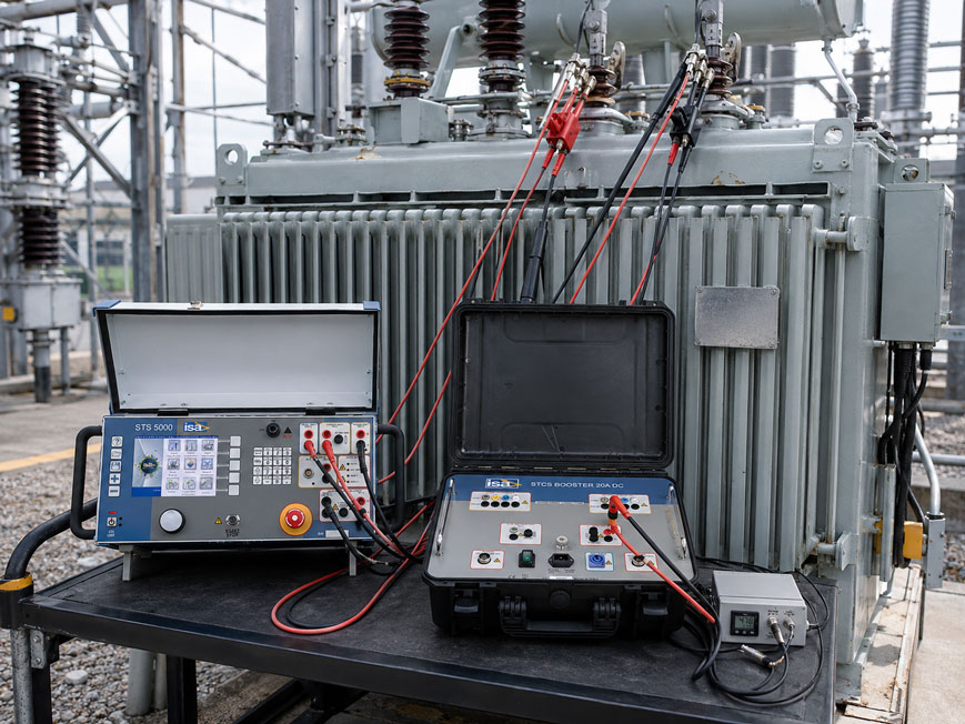
For professional transformer testing, ICS Schneider offers, among other systems, the ISA STS 5000 Multifunction Substation Test Set. The system supports, among other functions, winding resistance measurements on power transformers, dynamic resistance measurements on on-load tap changers and micro-ohm measurements. For higher test currents, the 20A DC Booster for winding resistance measurements is additionally available. Further solutions can be found under Power Transformer Testing and under Electrical Measuring and Test Equipment at ICS Schneider.
Table of Contents
- Why measure winding resistance?
- Measurement principle using DC current
- Why four-wire measurement is required
- Why the measured value needs time to stabilise
- Selecting the correct test current
- Avoiding excessively high test current
- Why winding temperature is critical
- Correcting resistance to a reference temperature
- Calculation example for a copper winding
- Which temperature should be used?
- Comparing phases with one another
- Tap changers and winding resistance
- Connecting test leads correctly
- Safely discharging the transformer after measurement
- Why demagnetisation can be useful
- Typical fault patterns
- Practical example: different measured values on the same winding
- Recommended test procedure
- Suitable transformer test equipment from ICS Schneider
- Conclusion
- FAQ
Why measure winding resistance?
Winding resistance measurement evaluates the complete current-carrying path between the accessible transformer terminals.
Depending on the transformer, this includes:
- winding conductors,
- internal connections,
- soldered and welded joints,
- bushing connections,
- tap changer contacts,
- connection leads between the winding and tap changer.
Deviating resistance values may indicate
- loose or corroded connections,
- damaged conductors or strands,
- increased contact resistance,
- faulty tap changer contacts,
- partial interruptions,
- certain winding faults.
The measurement is therefore particularly useful:
- during commissioning,
- after transport or repair,
- during periodic testing,
- after abnormalities during operation,
- for condition assessment of a tap changer.
The measured value becomes particularly meaningful not as a single value, but when compared with the other phases, previous measurements and manufacturer or factory values.
Measurement principle using DC current
The winding resistance is determined using direct current.
The basis is Ohm’s law:
R = U / I
The test instrument injects a defined DC current through the winding under test and simultaneously measures the voltage drop.
From:
test current I
and:
voltage drop U
the resistance is calculated.
The resistance values can be very small
Depending on the transformer and winding, they may lie, for example, in the range of:
- ohms,
- milliohms,
- or significantly below.
The resistance of a test lead or a poor contact point can therefore already be greater than the actual change in winding resistance being investigated.
For this reason, a simple two-wire measurement is unsuitable for precise measurements.
Why four-wire measurement is required
In four-wire or Kelvin measurement, the current path and voltage measurement are separated.
Two leads carry the test current
I+ and I−
Two separate leads measure the voltage
U+ and U−
Only a very small measuring current flows through the voltage-sensing leads.
This means that the resistance of:
- test leads,
- current clamps,
- contact points in the current path
has far less influence on the measurement result.
The position of the sense connections is important
The voltage measurement contacts should preferably be positioned:
inside the current contacts
directly on the connection being evaluated.
This allows the voltage drop across the desired current path to be measured as accurately as possible.
Especially for resistance values in the milliohm range, four-wire measurement is not merely a convenience feature, but a prerequisite for reproducible results.
Why the measured value needs time to stabilise
A transformer winding has a high inductance.
In an idealised RL circuit, the current does not rise instantaneously after a DC voltage is applied.
In simplified form:
i(t) = IEnd · (1 − e−t/τ)
with the time constant:
τ = L / R
With:
- high inductance
L, - low winding resistance
R
the time constant can be correspondingly large.
The first displayed resistance value is therefore not automatically the correct value
During magnetisation of the core:
- test current,
- voltage drop,
- calculated resistance
continue to change.
The value should only be stored once the test current and the calculated resistance are sufficiently stable.
With large transformers this may take time
Depending on:
- transformer size,
- winding,
- connection configuration,
- test voltage,
- test current,
- core saturation
stabilisation can take from a few seconds to several minutes.
A value recorded during the settling period can be incorrect even when using a highly accurate measuring instrument.
Selecting the correct test current
The test current influences both stability and measurement duration.
If the current is very low:
- magnetisation of the core may take longer,
- the measured value may be noisier,
- stabilisation may take longer.
A higher DC current can stabilise the measurement and bring the transformer more quickly into a suitable magnetic state.
As a commonly used guideline
a test current greater than approximately:
1% of the rated current of the winding under test
is often used for transformer winding resistance measurements.
At the same time, the test current should generally remain well below:
15% of the winding rated current
.
However, the exact selection depends on:
- transformer,
- winding,
- test instrument,
- manufacturer instructions,
- applied test procedure.
More current is not automatically better
The test current should allow a stable measurement condition without unnecessarily heating the winding.
Avoiding excessively high test current
The test current generates power loss in the winding:
P = I² · R
This increases the winding temperature.
Since electrical resistance itself is temperature-dependent, an excessively high test current changes the very quantity being measured.
Example
If a relatively small winding is subjected to an unnecessarily high DC current for a prolonged period, the resistance may continuously increase during the measurement series.
The tester could incorrectly interpret this as:
- an unstable contact,
- a tap changer problem,
- a measuring instrument fault.
In reality, only the winding conductor is heating up.
A suitable test current is therefore a compromise between rapid stabilisation and the lowest possible self-heating.
Why winding temperature is critical
Metallic conductors have a positive temperature coefficient.
This means:
temperature increases → resistance increases
and:
temperature decreases → resistance decreases
A resistance value without an associated temperature value is therefore of only limited use for long-term comparison.
Example
A copper winding is measured once at:
20 °C
and a few months later at:
35 °C
.
Even with an electrically unchanged winding, the second raw value will be higher.
A comparison of:
R20 °C ↔ R35 °C
without temperature correction can therefore lead to an incorrect diagnosis.
Correcting resistance to a reference temperature
To compare measurements taken at different temperatures, they are converted to a common reference temperature.
A commonly used relationship is:
Rref = Rm · (Tref + k) / (Tm + k)
where:
Rref= resistance at the reference temperature,Rm= actually measured resistance,Tref= desired reference temperature,Tm= winding temperature during measurement,k= material constant.
Typical constants
| Conductor material | k |
|---|---|
| Copper | approx. 234.5 °C |
| Aluminium | approx. 225 °C |
The reference temperature should not be selected arbitrarily.
It must match the:
- manufacturer documentation,
- factory test,
- applicable test specification,
- historical measurement series.
For trend evaluation, it is essential that all compared resistance values are referred to the same reference temperature.
Calculation example for a copper winding
A copper winding is measured at:
Rm = 100.0 mΩ
The winding temperature is:
Tm = 20 °C
The value is to be converted to:
Tref = 75 °C
.
Using:
k = 234.5 °C
results in:
R75 = 100.0 mΩ · (75 + 234.5) / (20 + 234.5)
and therefore approximately:
R75 = 121.6 mΩ
The difference is significant
The transformer has not changed electrically.
Nevertheless:
100.0 mΩ at 20 °C
and:
121.6 mΩ referred to 75 °C
differ by more than 20%.
This demonstrates why temperature correction must not be neglected when evaluating factory and field measurements.
Which temperature should be used?
The mathematical correction is only as accurate as the assumed winding temperature.
Especially in the field, this cannot always be measured directly.
A problematic example
is a transformer that was operated under high load for several hours immediately before testing.
After shutdown:
- winding,
- core,
- transformer oil,
- housing
cool down with different time constants.
An ambient temperature of:
20 °C
therefore does not automatically mean that the winding is also at:
20 °C
.
For reproducible measurements, therefore
- the thermal condition of the transformer should be documented,
- the specified or suitable temperature quantity should be recorded,
- comparative measurements should preferably be performed under similar thermal conditions.
If a transformer has been out of operation for a sufficiently long period, the winding may have largely equalised with the ambient or oil temperature.
Immediately after prior load operation, however, this assumption is critical.
Comparing phases with one another
For a three-phase transformer, comparing the phases is a particularly valuable plausibility check.
Under comparable conditions, electrically identical windings should have similar resistance values.
For example, the following would be conspicuous
| Phase | Temperature-corrected resistance |
|---|---|
| L1 | 101.2 mΩ |
| L2 | 100.8 mΩ |
| L3 | 107.9 mΩ |
The significantly higher third phase should be investigated.
Possible causes include:
- contact problem,
- loose connection,
- tap changer contact,
- different connection resistance,
- winding damage.
Do not apply limit values indiscriminately
The permissible deviation depends, among other things, on:
- transformer design,
- connection configuration,
- manufacturer specifications,
- test standard,
- measurement method.
A percentage phase difference should therefore not be assessed independently of the specific transformer design.
Tap changers and winding resistance
For transformers with tap changers, the measured resistance also includes the active contact and connection paths.
The measurement is therefore well suited to detecting abnormal contact resistance.
With a de-energised tap changer
the resistance values can be recorded successively for each permissible tap position.
The values should then be compared as:
resistance ↔ tap position
.
On-load tap changers
For an OLTC, dynamic resistance measurement can additionally provide valuable information about the transition between tap positions.
This can reveal, for example:
- contact interruptions,
- abnormal transition resistances,
- unstable switching operations.
In addition to winding resistance measurement, the ISA STS 5000 also supports dynamic resistance measurement of OLTC tap changers.
However, switching an inductive winding while DC current is being injected may only be carried out using a test instrument designed for this purpose and in accordance with the specified test procedure.
Connecting test leads correctly
At low resistance values, connection quality directly affects the result.
Before measurement, the contact points should be
- clean,
- free of oxidation,
- mechanically stable,
- contacted over a sufficiently large area.
Kelvin connection
The current clamps carry the test current.
The voltage-sensing contacts should be positioned as close as possible to the transformer terminal so that the contact resistance of the current clamps is not included in the measurement.
Do not move the leads during measurement
Movement can:
- change contact resistance,
- generate measurement noise,
- create hazardous conditions with an energised inductive winding.
The test leads should therefore be fully and mechanically securely connected before the test starts.
Safely discharging the transformer after measurement
During winding resistance measurement, energy is stored in the magnetic field.
For an inductance:
E = 1/2 · L · I²
If the current path is opened abruptly, the inductance attempts to maintain the current flow.
This can generate a high voltage.
Therefore
Never simply disconnect the test leads while the transformer is still carrying DC test current or has not been completely discharged.
A professional transformer resistance measurement system reduces the test current in a controlled manner and discharges the winding.
Only after clear release by the test instrument may:
- test clamps be removed,
- windings be reconnected,
- further tests be prepared.
The general safety and isolation rules for work on transformers must of course also be observed.
Why demagnetisation can be useful
A DC resistance measurement can leave residual magnetisation in the transformer core.
This residual magnetisation can affect subsequent tests or later energisation behaviour.
Possible effects include
- changed inrush current,
- influenced excitation current measurement,
- asymmetrical magnetic initial condition,
- influence on further magnetic diagnostic methods.
After a winding resistance measurement, controlled demagnetisation can therefore be useful depending on the test sequence.
For this purpose, ICS Schneider offers, for example, the ISA STDE Transformer Demagnetizer.
The device operates with alternating DC polarity and gradually reduces the residual magnetisation.
Important
Discharge ≠ demagnetisation
Discharge first ensures that the stored electrical or magnetic energy is reduced in a controlled manner and that the test setup can be safely disconnected.
Subsequent demagnetisation, on the other hand, brings the core into a more magnetically neutral condition.
Typical fault patterns
| Observation | Possible cause | Recommended check |
|---|---|---|
| Measured value continuously decreases for several minutes | Test current not yet stabilised | Allow more settling time |
| Measured value slowly increases during a long test | Winding is being heated by the test current | Reduce test current and monitor temperature |
| Value jumps when the clamp is moved | Poor contact | Clean the connection and check Kelvin clamps |
| One phase significantly higher | Contact, connection or winding problem | Compare phases and previous measured values |
| All current values higher than factory values | Higher winding temperature | Apply temperature correction |
| Values from different days are not reproducible | Different temperature or insufficient stabilisation | Document measurement conditions |
| Only one tap position is abnormal | Contact problem in the tap changer | Compare resistance values of all tap positions |
| Measurement takes unusually long | High inductance or unsuitable test current | Check test current and test instrument |
| Measured value includes lead resistance | Two-wire measurement or incorrect Kelvin connection | Use four-wire measurement |
| Abnormal excitation current after resistance test | Residual magnetisation of the core | Demagnetise the transformer |
| Sparking occurs when disconnecting the leads | Winding not completely discharged | Stop the test immediately and check the discharge procedure |
Practical example: different measured values on the same winding
During commissioning of a power transformer, a resistance of:
112.4 mΩ
was measured on a copper winding at a documented winding temperature of:
50 °C
.
During a later maintenance test, the resistance is only:
104.6 mΩ
.
At first glance, this appears to indicate a significant change.
However, the second measurement was carried out at
30 °C
.
The raw values must therefore not be compared directly.
Correct procedure
- Correct both measurements to the same reference temperature.
- Compare phase values of the same winding.
- Check the tap position.
- Compare test current and stability criterion.
- Only then carry out a trend assessment.
After temperature correction, the values may be nearly identical.
Without documented temperature, a completely normal temperature-related change could incorrectly have been interpreted as a winding problem.
Recommended test procedure
- Safely isolate the transformer: Carry out the specified safety and earthing measures.
- Identify the transformer: Document type, serial number, winding, rated current, vector group and tap position.
- Record the thermal condition: Determine the relevant temperature in accordance with the manufacturer or test procedure.
- Select the test instrument: Provide a suitable current range and sufficient test power.
- Use four-wire measurement: Connect current and sense leads separately.
- Check contact points: Ensure clean and mechanically stable connections.
- Define the test current: High enough for a stable measurement, but without unnecessary winding heating.
- Start the measurement: Build up the DC current in a controlled manner.
- Wait for stabilisation: Accept the value only after sufficient settling time.
- Store the resistance: Document raw value, test current and temperature together.
- Measure the other phases: Work under conditions that are as comparable as possible.
- Test all relevant tap positions: For transformers with a tap changer.
- Apply temperature correction: Refer all comparison values to the same reference temperature.
- Compare phases and history: Investigate abnormal deviations.
- Discharge the winding in a controlled manner: Remove the test leads only after release by the test instrument.
- Demagnetise if required: Especially before subsequent magnetic tests or recommissioning.
- Document the test: Store measured values, temperatures, tap position and assessment.
Suitable transformer test equipment from ICS Schneider
ISA STS 5000 Multifunction Substation Test Set
The ISA STS 5000 is a multifunctional test and commissioning system for substation applications.
For transformer testing, the system supports, among other functions:
- PT winding resistance,
- turns ratio,
- vector group testing,
- dynamic resistance measurement on OLTC tap changers,
- excitation current,
- no-load current,
- short-circuit impedance,
- leakage reactance,
- micro-ohm measurement.
20A DC Booster for winding resistance measurements
For winding resistance measurements with a higher DC current, the 20A DC Booster is available.
Key specifications include:
- maximum output current: 20 A DC,
- maximum output power: 400 W,
- used together with STS 5000 or STS 4000,
- current amplitude controlled via the STS system.
A higher available test current is particularly useful for low-resistance transformer windings and applications where a stable DC condition needs to be reached efficiently.
ISA STDE Transformer Demagnetizer
The STDE Transformer Demagnetizer is used to neutralise residual magnetisation after a winding resistance measurement.
The system offers, among other features:
- constant, voltage-limited DC current,
- up to 7 A DC test current,
- up to 70 V DC,
- automatic reversal of current direction.
Further equipment and accessories can be found under Power Transformer Testing at ICS Schneider.
Conclusion
Winding resistance measurement is one of the most important electrical condition tests on transformers. However, an apparently simple resistance value is only meaningful if the measurement conditions are controlled.
Four-wire measurement eliminates lead errors
Current and voltage measurement are separated so that test lead and contact resistances have as little influence as possible on the result.
Inductance determines the measurement duration
The test current must first stabilise. A value stored too early can differ significantly from the actual winding resistance.
The test current must match the winding
Too little current can result in long settling times and unstable measurements. Too much current heats the winding and therefore changes the resistance itself.
Temperature correction is essential for comparison
Measured values obtained at different temperatures must be converted to the same reference temperature before factory values, previous measurements or trends can be compared reliably.
The transformer must be safely discharged after measurement
A transformer winding is a large inductance. Test leads may only be removed after the DC current has been reduced in a controlled manner and the winding has been discharged.
Consider residual magnetisation
After a DC measurement, demagnetisation may be useful or required for subsequent tests.
For practical applications
Isolate the transformer → document winding and tap position → record temperature → establish Kelvin four-wire connection → select a suitable test current → wait for complete stabilisation → store measured value and temperature together → compare phases and tap positions → correct to a common reference temperature → discharge in a controlled manner → demagnetise if required → compare results with historical and manufacturer values.
FAQ: Measuring Transformer Winding Resistance Correctly
Why is transformer winding resistance measured?
The measurement is used to assess the current-carrying path and can indicate poor connections, damaged conductors, increased contact resistance or tap changer problems.
Is winding resistance measured with DC or AC current?
For classic winding resistance measurement, DC current is injected and the DC resistance is determined from current and voltage drop.
Why is four-wire measurement used?
Because the resistances being measured can be very small. Separate current and voltage leads largely eliminate lead and contact resistance from the measurement result.
What is a Kelvin measurement?
Kelvin measurement is another term for four-wire resistance measurement using separate current and voltage connections.
Why does resistance measurement on a transformer take so long?
Transformer windings have high inductance. After DC current is applied, a stable magnetic and electrical condition must first be reached.
Can I use the first displayed value?
No. The measured value should only be stored once the test current and resistance are sufficiently stable.
How high should the test current be?
The appropriate value depends on the transformer and test method. As a commonly used guideline, values above approximately 1% and below approximately 15% of the rated current of the winding under test are often used.
Why must the test current not be too high?
A high test current heats the winding. Since resistance increases with temperature, this can distort the measurement result.
Why does winding resistance change with temperature?
Copper and aluminium have a positive temperature coefficient. As conductor temperature increases, electrical resistance also increases.
How is winding resistance corrected to a reference temperature?
A commonly used formula is Rref = Rm × (Tref + k) / (Tm + k), where k depends on the conductor material.
Which value is used for copper?
For copper, a material constant of approximately 234.5 °C is typically used.
Which value is used for aluminium?
For aluminium, a material constant of approximately 225 °C is typically used.
Which reference temperature should I use?
The reference temperature depends on the manufacturer documentation, factory values and the applied test specification. For trend comparisons, all values must be corrected to the same temperature reference.
Can I simply use the ambient temperature?
Not always. Particularly immediately after load operation, the actual winding temperature can differ significantly from the ambient temperature.
Why should all three phases be compared?
For phases with the same design, abnormal deviations can be identified quickly. However, the assessment must take into account connection configuration, tap position and manufacturer specifications.
What can a significantly higher value in one phase indicate?
Possible causes include increased contact resistance, loose or corroded connections, tap changer problems or a fault in the winding path.
Does every tap position need to be measured?
For a comprehensive assessment of a transformer with a tap changer, measuring the relevant tap positions is useful because contact problems in individual positions can be identified.
What is dynamic resistance measurement on an OLTC?
The resistance or current behaviour during the switching operation of the on-load tap changer is evaluated in order to identify interruptions and abnormalities during contact transition.
Why must I not simply disconnect the test leads?
The transformer winding stores magnetic energy. If the DC current is interrupted suddenly, the inductance can generate a high voltage.
Does the transformer have to be discharged after measurement?
Yes. The test current must be reduced to zero in a controlled manner and the winding safely discharged according to the test instrument or test procedure.
What is the difference between discharge and demagnetisation?
Discharge establishes a safe electrical condition. Demagnetisation subsequently reduces the remaining residual magnetisation of the transformer core.
Why does the core remain magnetised after the measurement?
During winding resistance measurement, DC current flows through the winding for an extended period. This can leave remanent magnetisation in the core.
Can residual magnetisation affect further tests?
Yes. It can influence, among other things, energisation behaviour and subsequent magnetic measurements such as excitation current tests.
Which ICS test system is suitable for transformer winding resistance measurements?
The ISA STS 5000 supports, among other functions, PT winding resistance, dynamic OLTC resistance measurement and micro-ohm measurements.
Is a higher test current available for the STS 5000?
Yes. The 20A DC Booster enables resistance tests with up to 20 A DC and is used together with the STS 5000 or STS 4000.
Does ICS offer a device for demagnetisation?
Yes. The ISA STDE Transformer Demagnetizer is specifically designed to reduce residual magnetisation after winding resistance measurements.
Where can I find further transformer test equipment?
Further systems can be found under Power Transformer Testing at ICS Schneider.