


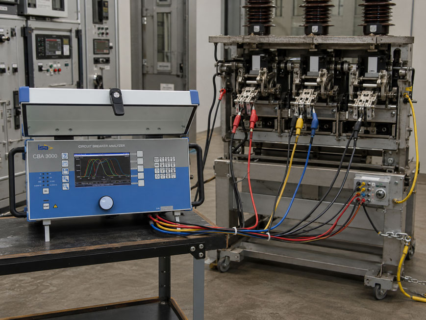
A circuit breaker may appear electrically faultless while still operating mechanically too slowly, unevenly or with poor repeatability. Particularly with medium- and high-voltage circuit breakers, changes in the operating mechanism, trip mechanism, coils, damping or contact mechanism can cause individual poles to no longer operate within the specified time.
A switching time or timing test is therefore used to measure the time between a defined opening or closing command and the actual change of state of the main contacts.
Three quantities are particularly relevant:
- opening time,
- closing time,
- timing synchronism or pole synchronism of the individual phases.
Modern circuit breaker analyzers can additionally:
- record auxiliary contacts,
- control opening and closing coils,
- record coil currents,
- record travel and speed profiles,
- measure static and dynamic contact resistance,
- automatically test complex operating sequences.
A clearly defined time reference is essential for meaningful results. The start signal, contact channels, coil control and evaluation must be identical for recurring tests. Only then can current values be reliably compared with manufacturer specifications and previous measurements.
Suitable test equipment can be found under electrical measuring and test equipment at ICS Schneider or under circuit breaker test equipment.
Table of Contents
- Why is circuit breaker timing tested?
- What does a circuit breaker timing test measure?
- What is opening time?
- What is closing time?
- What does pole synchronism or pole discrepancy mean?
- Calculating pole synchronism correctly
- Measuring main contacts correctly
- Circuit breakers with multiple interrupter units per pole
- Do not confuse auxiliary contacts with main contacts
- Which time reference should be used?
- Controlling opening and closing coils correctly
- Why should coil current also be measured?
- Influence of control voltage on switching time
- Why multiple operations are useful
- First-trip testing after an extended period of inactivity
- Distinguishing O, C, CO and O-CO operating sequences
- Adding travel and speed analysis
- Considering pre-insertion resistor contacts
- Testing a circuit breaker grounded on both sides
- Safety when connecting the test equipment
- Which limits should the results be compared with?
- Why trend values are often more important than individual values
- Practical example: three-pole high-voltage circuit breaker
- Combined diagnosis using timing and coil current
- Typical fault patterns
- What should be included in a test report?
- Recommended test procedure
- Suitable circuit breaker test equipment from ICS Schneider
- Conclusion
- FAQ
Why is circuit breaker timing tested?
Circuit breakers must safely interrupt fault currents within defined times and reliably reclose circuits.
It is not sufficient for the breaker simply to:
open
or:
close
.
The timing sequence must also be correct.
Opening too slowly
can increase the actual fault-clearing time.
Closing too slowly
can indicate problems with the operating mechanism, closing coil or stored-energy mechanism.
Poles operating at different times
can result in undesirable electrical and mechanical stresses.
A timing test is therefore typically performed:
- during commissioning,
- during periodic maintenance,
- after repairs,
- after work on the operating mechanism,
- in the event of abnormal switching behavior,
- after an extended period of inactivity.
What does a circuit breaker timing test measure?
The basic principle is simple:
start signal → mechanical breaker movement → contact state change
The test instrument generates or detects a clearly defined starting point and then records when the respective contacts change state.
For a three-pole circuit breaker, for example, this produces
tL1
,
tL2
and:
tL3
.
These individual times can be used to determine:
- opening time or closing time for each pole,
- earliest contact,
- latest contact,
- pole synchronism.
What is opening time?
For an electrically tripped circuit breaker, the opening time generally describes the interval between initiation of the opening operation and separation of the relevant main or arcing contacts.
In a practical timing measurement
the typical start point is:
energization of the trip coil
or the defined opening command.
The test instrument then records the point in time at which the respective main contact opens.
Example
| Pole | Measured opening time |
|---|---|
| L1 | 31.8 ms |
| L2 | 32.1 ms |
| L3 | 32.7 ms |
This immediately shows that L1 opened first and L3 opened last.
Important regarding the definition
Normative terminology and the specific evaluation method used by the test instrument must be taken into account.
According to the IEC definition, the opening time of a circuit breaker refers to the interval until separation of the arcing contacts in all poles.
For practical condition diagnostics, the individual times of each pole are also evaluated.
What is closing time?
The closing time correspondingly describes the interval between initiation of the closing operation and contact touch.
Typical starting point
is:
energization of the closing coil
.
Typical end point
is the state change of the respective main contact from:
open → closed
.
Example
| Pole | Measured closing time |
|---|---|
| L1 | 54.2 ms |
| L2 | 54.8 ms |
| L3 | 55.0 ms |
The closing time alone already provides considerable information about the mechanism.
However, it becomes even more informative when combined with:
- pole synchronism,
- coil current,
- travel,
- speed.
What does pole synchronism or pole discrepancy mean?
In a three-pole circuit breaker, the poles should operate within a specified time window.
However, the individual contacts do not reach their switching state at exactly the same microsecond.
A small time difference occurs.
This difference is often referred to as
- pole synchronism,
- pole discrepancy,
- phase discrepancy,
- Pole Discrepancy,
- Pole Discordance.
For timing evaluation, this normally means the difference between the first and last pole to operate during the same operation.
Pole synchronism should be evaluated separately for opening and closing. A breaker may show good synchronism when opening but still be abnormal when closing.
Calculating pole synchronism correctly
In simplified form:
ΔtPole = tmax − tmin
Opening example
Measured times:
L1 = 31.8 ms
L2 = 32.1 ms
L3 = 32.7 ms
Then:
ΔtPole = 32.7 ms − 31.8 ms
which equals:
0.9 ms
.
Important
All compared times must refer to:
- the same switching operation,
- the same contact type,
- the same trigger point.
It would not be meaningful, for example, to compare a main contact on L1 with an auxiliary contact on L2.
Measuring main contacts correctly
In a conventional switching-time measurement, the timing inputs of the test instrument are connected to the main current paths of the circuit breaker.
The test instrument can thereby detect the states:
contact closed
and:
contact open
.
For a three-pole breaker
at least one timing channel per pole is required.
If each phase has several separately accessible interrupter units, correspondingly more channels may be required.
Consider contact bounce
Mechanical contacts may briefly bounce during closing.
A suitable circuit breaker analyzer records these events with sufficient time resolution or evaluates them according to a defined method.
For comparisons extending over several years, the following should therefore preferably remain the same:
- test method,
- contact configuration,
- evaluation logic.
Circuit breakers with multiple interrupter units per pole
High-voltage circuit breakers can have several interrupter units or breaking chambers per pole.
There are then two different synchronization questions
First:
How simultaneously do L1, L2 and L3 operate?
Second:
How simultaneously do the individual interrupter units within one pole operate?
Both can be diagnostically relevant.
A test instrument with a sufficient number of timing inputs
allows simultaneous recording of all accessible:
- main contacts,
- resistor contacts,
- auxiliary contacts.
This reveals not only differences between phases but also differences within an individual pole.
Do not confuse auxiliary contacts with main contacts
Circuit breakers also frequently have auxiliary contacts such as:
52a
and:
52b
.
These are used, for example, for:
- control,
- interlocking,
- status feedback,
- protection logic.
Their switching time is not identical to the main-contact time
An auxiliary contact may be designed to switch:
- before the main contact,
- after the main contact.
An auxiliary-contact measurement must therefore not automatically be interpreted as the opening or closing time of the main current path.
However, the relative timing can be diagnostically valuable
If, for example, the time interval between:
main contact
and:
auxiliary contact
changes compared with previous tests, this may indicate changes in the mechanism or adjustment.
Which time reference should be used?
Switching time is always the difference between two points in time.
The starting point must therefore be clearly defined.
Typical internal trigger
The test instrument itself sends the:
OPEN
or:
CLOSE
command and starts timing simultaneously.
This provides a highly reproducible reference.
Trigger via coil current
Alternatively, measurement can begin as soon as the current through an opening or closing coil exceeds a defined threshold.
External trigger
For certain test tasks, an external binary contact or separate control signal can serve as the time reference.
For recurring tests, the trigger principle should not be changed without taking this change into account during evaluation.
Controlling opening and closing coils correctly
For a complete timing test, the test instrument often directly controls the circuit breaker’s:
- opening coil or trip coil,
- closing coil or close coil
via the appropriate control contacts.
The following must be known before testing
- rated control voltage,
- permissible voltage tolerance,
- circuit diagram,
- control logic,
- coil assignment.
For circuit breakers with several separate operating mechanisms or phase-selective control, several independent coil channels may be required accordingly.
Why should coil current also be measured?
The contact timing alone shows:
when
the circuit breaker operates.
The coil-current curve can provide additional information about:
why
the switching time has changed.
Typical trip-coil current curve
After energization, the coil current initially rises.
The magnetic armature then begins to move.
This changes the coil inductance and therefore also the current waveform.
Further characteristic points may be associated with:
- release of the mechanism,
- armature movement,
- end stop,
- switch-off of the coil current.
A change in waveform can indicate
- mechanical stiffness,
- problems with the trip mechanism,
- undervoltage,
- changed coil resistance,
- contact problems in the control circuit.
Influence of control voltage on switching time
An opening or closing coil does not operate independently of its supply voltage.
If the control voltage decreases
for example:
- the coil current may rise more slowly,
- the magnetic force may be lower,
- the armature may operate later,
- the total switching time may increase.
Timing results should therefore only be compared directly if the control conditions are also comparable.
The test report should therefore include the actual control voltage
and not only:
rated voltage according to nameplate
.
Some test instruments can record the voltage directly during the operation.
Why multiple operations are useful
A single switching operation may randomly be faster or slower.
Repeatability is therefore also important for condition assessment.
Example
| Operation | L1 | L2 | L3 |
|---|---|---|---|
| Opening 1 | 31.8 ms | 32.1 ms | 32.7 ms |
| Opening 2 | 31.9 ms | 32.2 ms | 32.6 ms |
| Opening 3 | 31.8 ms | 32.1 ms | 32.8 ms |
These results are highly reproducible.
If, on the other hand, L3 varies, for example, between:
32 ms
and:
45 ms
, not only the mean value but particularly the poor repeatability is abnormal.
First-trip testing after an extended period of inactivity
An important special case is the so-called first-trip test.
This specifically examines the first opening operation after an extended period of inactivity.
Why is this interesting?
A circuit breaker may behave differently on its first opening after several months than during several immediately consecutive operations.
Possible causes include:
- hardened or aged lubricants,
- increased initial friction,
- corrosion,
- mechanical deposits,
- linkages that have not moved for a long time.
Operating the breaker several times before measurement can conceal the fault
The mechanism has already been moved and may temporarily return to normal behavior.
A first-trip measurement should therefore – if it forms part of the test concept – be carried out before unnecessary prior switching operations.
Distinguishing O, C, CO and O-CO operating sequences
In addition to simple individual operations, defined switching sequences can also be tested.
O – Open
closed → open
C – Close
open → closed
CO – Close-Open
Closing followed immediately by opening.
O-CO or O-C-O
Depending on the circuit breaker and test requirements, automatic reclosing sequences can also be investigated.
Such tests evaluate not only individual opening and closing times but also:
- interval times,
- mechanism charging,
- response capability during rapid sequences,
- control-circuit operating sequence.
The permissible test sequence must be suitable for the respective circuit breaker.
Adding travel and speed analysis
A contact timing measurement shows the electrical switching point.
However, it does not completely show how the mechanism moves before and after this point.
With a travel transducer
the position over time can additionally be recorded:
s = f(t)
.
Depending on the breaker, this can be used to determine:
- total travel,
- contact travel,
- opening speed,
- closing speed,
- overtravel,
- return movement or rebound.
This combination is particularly informative
An abnormal timing result can then, for example, be differentiated into:
- delayed start of movement,
- insufficient movement speed,
- incorrect mechanical end position.
Considering pre-insertion resistor contacts
Certain high-voltage circuit breakers have closing resistors or:
Pre-Insertion Resistors (PIR)
.
Their contacts have an intentionally defined timing sequence relative to the main contacts.
During a timing test, therefore
- PIR contacts,
- main contacts
must be recorded and evaluated separately.
A suitable test instrument provides correspondingly configurable contact channels.
Testing a circuit breaker grounded on both sides
When working on high-voltage systems, grounding is an essential part of the safety concept.
However, conventional contact timing measurement can be more difficult when both sides of the circuit breaker are grounded.
Why?
The grounding connections create additional low-resistance current paths.
A simple continuity measurement can then no longer clearly distinguish the state of the main contact.
BSG – Both Sides Grounded
Special circuit breaker analyzers can use suitable measuring methods to perform a test while the grounding remains in place on both sides.
This can provide significant safety advantages, particularly when testing high-voltage circuit breakers.
A BSG test may only be carried out using a test method and measuring instrument explicitly designed for this purpose.
Safety when connecting the test equipment
Circuit breaker timing tests are performed on equipment that can store considerable mechanical and electrical energy.
Before connection, the following must therefore be considered, among other things
- isolation according to the applicable plant procedure,
- protection against reconnection,
- verification of absence of voltage or defined test condition,
- grounding and short-circuiting according to the installation,
- stored energy of the breaker operating mechanism,
- control voltage in the control cabinet,
- possible automatic switching commands.
The operating mechanism remains particularly hazardous mechanically
Even when the main current circuit is de-energized, the following may still be present:
- charged springs,
- hydraulic pressure,
- pneumatic pressure,
- control voltages.
The test must therefore only be carried out by appropriately qualified personnel in accordance with the specified plant and manufacturer procedures.
Which limits should the results be compared with?
The data for the specific circuit breaker are primarily decisive when assessing the measured times.
Suitable comparison data include, for example
- manufacturer specifications,
- commissioning report,
- previous maintenance tests,
- factory reference values,
- applicable standards and operational requirements.
It is not appropriate to apply a single general millisecond limit to all circuit breakers regardless of design, voltage level and operating mechanism.
Particularly informative
is the comparison of a breaker with its own historical measurement values.
A gradual change can therefore be detected before an absolute limit is exceeded.
Why trend values are often more important than individual values
Example:
| Test | Opening time L3 |
|---|---|
| Commissioning | 31.9 ms |
| Year 2 | 32.2 ms |
| Year 4 | 33.0 ms |
| Year 6 | 34.8 ms |
| Year 8 | 37.1 ms |
Each individual value might still be within an acceptable range.
However, the trend shows a continuous change.
If it is observed at the same time
that:
- L1 remains stable,
- L2 remains stable,
- only L3 becomes slower,
the cause is likely to be specific to the third pole or its mechanism.
Practical example: three-pole high-voltage circuit breaker
A three-pole circuit breaker is tested during maintenance.
Opening measurement
| Pole | Time |
|---|---|
| L1 | 32.0 ms |
| L2 | 32.4 ms |
| L3 | 36.8 ms |
The difference is therefore:
36.8 ms − 32.0 ms = 4.8 ms
Comparison with previous year
In the previous year, L3 was:
32.6 ms
.
L1 and L2 are almost unchanged.
Initial interpretation
The deviation is probably not caused by a common trigger error because only one pole has changed significantly.
The following are now additionally examined:
- coil current L3,
- travel profile L3,
- mechanical linkage,
- lubrication,
- trip mechanism.
Coil current unchanged, but movement starts late
This points more toward a mechanical problem between triggering and the actual start of movement.
If the coil current instead rises unusually slowly
the following should additionally be examined:
- control voltage,
- line resistance,
- coil,
- control contacts.
Combining several measured quantities therefore provides considerably more diagnostic information than opening time alone.
Combined diagnosis using timing and coil current
| Timing | Coil current | Possible interpretation |
|---|---|---|
| Longer switching time | Curve unchanged | Mechanical delay after coil pickup possible |
| Longer switching time | Current rises significantly more slowly | Undervoltage or control-circuit problem possible |
| Switching time varies significantly | Current curve also varies | Electrical or mechanical operating process unstable |
| Switching time stable | Peak current increasingly higher | Investigate coil or mechanism more closely |
| One pole slower | Only its curve is abnormal | Phase-specific fault likely |
| All poles slower simultaneously | All coils show a similar change | Check common control voltage or operating condition |
This assignment is a diagnostic aid and does not replace specific assessment based on the breaker design and manufacturer documentation.
Typical fault patterns
| Observation | Possible cause | Recommended check |
|---|---|---|
| All three poles open significantly later | Control voltage too low or common mechanism stiff | Measure control voltage and coil current |
| Only one pole opens late | Phase-specific mechanism stiff | Check travel profile and mechanism of this pole |
| Pole synchronism progressively deteriorates | Uneven mechanical ageing or adjustment | Compare trend values and individual poles |
| Closing time varies significantly | Operating mechanism or interlock not working reproducibly | Perform several closing operations and travel analysis |
| First opening slow, subsequent openings normal | Effect of inactivity or increased initial friction | Evaluate first-trip result |
| Auxiliary-contact timing abnormal, main contacts normal | Auxiliary switch or its adjustment has changed | Investigate auxiliary contact separately |
| Coil current starts late | Control contact, wiring or triggering | Check start signal and control voltage |
| Coil current rises too slowly | Undervoltage or high contact resistance | Measure voltage directly at the coil during operation |
| Coil current normal, contact movement delayed | Mechanical problem likely | Check operating mechanism and travel profile |
| Timing differs with every measurement | Mechanical scatter or unstable test conditions | Perform several identical operations |
| Contact channel permanently indicates closed | Incorrect wiring or grounding path | Check connection and BSG situation |
| Measurement with both sides grounded is implausible | Conventional contact measurement unsuitable | Use BSG-capable test method |
| Opening time does not match old report | Different trigger or different definition | Compare test procedure and time reference |
| Several interrupters of one pole operate differently | Mechanism or interrupter unit not synchronized | Evaluate each interrupter unit separately |
What should be included in a test report?
A timing report should contain more than just three time values.
At minimum, it is useful to include
- plant and breaker identification,
- manufacturer and type,
- serial number,
- date,
- test instrument and serial number,
- test configuration,
- control voltage,
- switching operation,
- trigger type,
- opening time per pole,
- closing time per pole,
- pole synchronism during opening,
- pole synchronism during closing,
- auxiliary-contact times, if measured,
- coil current, if measured,
- travel values, if measured,
- comparison values or limits,
- evaluation.
Particularly valuable
is archiving the complete measurement curves.
If an abnormality occurs later, not only individual numbers but the complete timing sequence can then be compared with earlier tests.
Recommended test procedure
- Clearly identify the circuit breaker: Document manufacturer, type and serial number.
- Check manufacturer documentation: Determine target times, permissible operating sequences and limits.
- Define plant condition: Perform isolation, grounding and work authorization according to the plant procedure.
- Consider stored mechanical energy: Take spring, hydraulic or pneumatic operating mechanisms into account.
- Check circuit diagram: Clearly identify opening and closing coils.
- Determine control voltage: Document rated value and actual supply.
- Configure the test instrument: Define breaker type and contact channels.
- Connect main contacts: Clearly assign L1, L2 and L3.
- Connect additional interrupter units: If the breaker has multiple breaks per pole.
- Configure PIR contacts: If present.
- Connect auxiliary contacts: If their timing is to be evaluated.
- Connect opening and closing coils: Connect control circuits according to the circuit diagram.
- Activate coil-current measurement: If diagnostic information is required.
- Activate control-voltage measurement: Record actual voltage during the operation.
- Install travel transducer: If travel and speed analysis is planned.
- Check BSG situation: With both sides grounded, use only a suitable method.
- Define trigger: Clearly specify internal command, coil current or external signal.
- Perform First Trip first: If this test is planned.
- Measure a single opening operation: Store the times of all poles.
- Calculate pole synchronism: Compare earliest and latest pole.
- Measure a single closing operation: Store the times of all poles.
- Calculate closing synchronism: Again compare earliest and latest pole.
- Repeat measurement: Check repeatability.
- Test additional operating sequences: Only if intended for the breaker.
- Evaluate coil-current curves: Identify abnormal mechanical or electrical phases.
- Evaluate travel profile: If a travel transducer was used.
- Compare with manufacturer values: Assess absolute values.
- Compare with previous tests: Identify trends.
- Investigate abnormal poles separately: Narrow down mechanism, coil and control circuit.
- Archive the test report: Store results and complete curves.
Suitable circuit breaker test equipment from ICS Schneider
ISA CBA1000 – circuit breaker timing and diagnostics for medium and high voltage
The ISA CBA1000 is designed for timing and diagnostic testing of medium-, high- and extra-high-voltage circuit breakers.
Key functions include:
- measurement of opening and closing times,
- measurement of pole synchronism or Pole Discordance,
- 6 main-contact and 6 resistor-contact inputs,
- up to 4 opening/closing coil controls,
- 4 timing inputs for auxiliary contacts,
- measurement of coil and motor current,
- travel analysis,
- integrated 200 A micro-ohmmeter for static and dynamic contact-resistance measurements,
- optional testing with both sides grounded.
This allows timing, contact state and additional diagnostic quantities to be recorded within one common test procedure.
ISA CBA2000 – comprehensive circuit breaker analysis with numerous timing channels
The ISA CBA2000 is intended for more extensive diagnostic tasks.
Depending on the configuration, available functions include:
- up to 18 main-contact and 18 resistor-contact inputs,
- 12 auxiliary timing inputs,
- up to 4 opening or closing coil controls,
- measurement of opening time, closing time and Pole Discordance,
- first-trip testing,
- coil and motor current measurement,
- travel analysis,
- static and dynamic contact-resistance measurement with integrated 200 A micro-ohmmeter,
- optional BSG testing.
The large number of timing channels is particularly useful for circuit breakers with multiple interrupter units or additional resistor contacts.
ISA CBA3000 – all-in-one circuit breaker test instrument
The ISA CBA3000 combines extensive timing, travel and resistance measurements in a single system.
Functions include:
- 16 or optionally 24 freely configurable inputs for main, PIR and auxiliary contacts,
- 2, 4 or 6 opening/closing coil commands,
- three-phase first-trip testing,
- travel and speed analysis using analog and digital travel transducers,
- measurement of battery or control voltage,
- coil and motor current measurement,
- static and dynamic contact-resistance measurement,
- testing with both sides grounded,
- automatic testing of minimum trip voltage,
- storage and evaluation of results.
A major advantage is that, once the connections have been set up, various tests can be performed within a prepared test plan without having to completely rewire the measuring setup for every individual test.
TDMS – Test and Data Management Software
Consistent documentation is particularly important for recurring tests.
Depending on the test instrument used, the associated TDMS software can be used to:
- manage test plans,
- analyze results,
- archive measurements,
- compare historical results,
- create test reports.
Particularly for switching-time measurements, long-term comparability is a major advantage because gradual changes in the mechanism can be detected much earlier.
Further solutions can be found under circuit breaker test equipment at ICS Schneider.
Conclusion
Timing testing is one of the most important diagnostic methods for medium- and high-voltage circuit breakers.
Opening time and closing time must be clearly defined
Only if the start signal and contact state change are recorded in the same way during every test can measured values be reliably compared.
The individual times of all poles are just as important as the overall time
A single slow pole can be hidden in an overall value.
Pole synchronism shows the time difference between the phases
It is determined from the earliest and latest contact point of the same switching operation.
Auxiliary contacts are not main contacts
Their timing can be diagnostically important, but must not be equated with main-contact timing.
Coil current considerably expands the diagnostic capability
It helps distinguish whether a timing change is more likely to originate from the control circuit, coil or mechanism.
The actual control voltage must be taken into account
Reduced coil voltage can directly influence the measured switching time.
First Trip can reveal problems caused by inactivity
A slow first operation may already appear normal again after several switching operations.
Travel analysis complements contact timing
Travel and speed show how the breaker operates mechanically, not only when the contact switches.
A special BSG method is required when both sides are grounded
A conventional continuity measurement can be distorted by the grounding connections.
Manufacturer values and historical measurements are decisive
A general millisecond limit is not suitable for every circuit breaker.
For practical applications
Clearly identify the circuit breaker → obtain manufacturer values and previous reports → establish a safe test condition → correctly assign main, auxiliary and, where applicable, PIR contacts → connect opening and closing coils → define a consistent trigger → record control voltage and coil current → perform First Trip first where applicable → measure opening time of all poles → calculate pole synchronism → measure closing time and closing synchronism → repeat measurements and check scatter → add travel profile and contact resistance if required → compare current values with manufacturer data and historical trends → investigate abnormalities specifically from a mechanical or electrical perspective → archive complete measurement curves and test conditions.
FAQ: Circuit Breaker Timing, Opening Time and Pole Synchronism
What is measured during a circuit breaker timing test?
The time between a defined opening or closing command and the change of state of the main contacts is measured. In addition, the timing difference between the individual poles is frequently evaluated.
What is the opening time of a circuit breaker?
It describes the interval between initiation of the opening operation and separation of the switching contacts. For practical diagnostics, the individual times of the respective poles are also considered.
What is closing time?
It describes the interval between initiation of the closing operation and contact touch or closure.
What does pole synchronism mean?
Pole synchronism describes the timing difference between the individual poles of a multipole circuit breaker during the same opening or closing operation.
How is pole synchronism calculated?
Usually, the difference between the longest and shortest individual time is calculated: Δt = tmax − tmin.
Do opening and closing synchronism have to be evaluated separately?
Yes. A circuit breaker may have good synchronism during opening but still be abnormal during closing.
How many timing channels are required?
For a simple three-pole breaker, at least one channel per pole. More channels are required for multiple interrupter units, PIR contacts or additional auxiliary contacts.
What is Pole Discrepancy?
Pole Discrepancy or Pole Discordance refers to the timing difference between the operating poles or phases.
Can I use an auxiliary contact to measure main-contact timing?
Not directly. Depending on the design, auxiliary contacts may switch earlier or later than the main contacts and therefore have their own timing relationship.
Why are auxiliary contacts measured nevertheless?
They are important for control, interlocking and status feedback functions. Changes in their timing can also indicate a change in mechanical adjustment.
What is the trigger in a timing measurement?
The trigger is the defined starting point of the time measurement, for example the opening command issued by the test instrument, the closing command or a defined coil-current threshold.
Why must the trigger always remain the same?
Different starting definitions produce different timing values. The same measurement method must therefore be used for reliable trend assessment.
Why is coil current measured?
The current waveform provides information about the electrical and mechanical sequence of the trip or closing mechanism and can help identify the cause of abnormal switching times.
Can low control voltage affect opening time?
Yes. Lower coil voltage can result in a slower current rise and therefore delayed mechanical operation.
Should the control voltage be documented in the test report?
Yes. Particularly for comparative measurements, the actual control voltage present during the switching operation is relevant.
Why should several switching operations be measured?
Several identical operations show repeatability. Strongly varying times can already indicate an unstable mechanism.
What is a first-trip test?
It examines the first switching operation after an extended period of inactivity and can reveal problems that temporarily disappear after several operations.
Why should the breaker preferably not be operated several times before a first-trip test?
Repeated movement may already free stiff or poorly lubricated mechanical components and conceal the original condition.
What does O mean in a circuit breaker test?
O stands for Open, meaning a single opening operation.
What does C mean?
C stands for Close, meaning a single closing operation.
What does CO mean?
CO refers to a closing operation followed by an opening operation in accordance with the defined switching sequence.
What additional information does travel analysis provide?
It records the mechanical travel of the operating mechanism or contact over time and enables assessment of speed, stroke, overtravel and other movement parameters.
Can a timing value be normal even if the mechanism already has problems?
Yes. A breaker may still reach the correct contact timing even though, for example, movement speed or overtravel has already changed. Additional travel analysis can therefore be useful.
What are PIR contacts?
PIR stands for Pre-Insertion Resistor. In suitably designed high-voltage circuit breakers, resistor contacts are switched in a defined timing sequence before or in conjunction with the main contacts.
What does BSG mean?
BSG stands for Both Sides Grounded and refers to a test method in which the circuit breaker can remain grounded on both sides during testing.
Why does conventional contact measurement not always work when both sides are grounded?
The grounding connections create parallel conductive paths. A simple continuity measurement may therefore not clearly identify the state of the main contact.
Which limit applies to pole synchronism?
The primary criteria are manufacturer specifications, breaker type, applicable standards and operational requirements. A general millisecond limit should not be used without reference to the specific circuit breaker.
Why are historical measurement values important?
They make it possible to detect gradual changes even when the current individual value is still within an acceptable limit.
What does it mean if only one pole keeps getting slower?
This indicates a phase-specific change and should be further investigated by checking the mechanism, coil current and travel profile of that pole.
What does it mean if all poles become slower at the same time?
Common causes such as control voltage, a shared operating mechanism, temperature or changed test conditions should be investigated first.
Can contact bounce influence the measurement?
Yes. A timing analyzer specifically designed for circuit breakers with suitable time resolution and defined evaluation should therefore be used.
Which instrument is suitable for conventional circuit breaker timing tests?
The ISA CBA1000 enables, among other functions, measurement of opening time, closing time, Pole Discordance, coil current and travel profiles.
Which instrument is suitable when many contact channels are required?
The ISA CBA2000 provides up to 18 main-contact and 18 resistor-contact inputs as well as additional auxiliary timing inputs.
Which instrument is suitable for particularly comprehensive circuit breaker diagnostics?
The ISA CBA3000 combines timing, First Trip, travel analysis, coil and motor current measurement, BSG testing and static and dynamic contact-resistance measurement in one system.
Where can I find further circuit breaker test equipment?
Further solutions can be found under circuit breaker test equipment at ICS Schneider.