


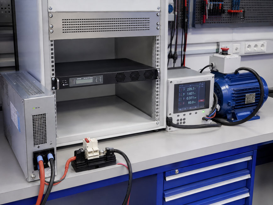
An electrical device designed for 60 Hz cannot be realistically tested in Germany simply because a 230 V mains supply is available. For a reproducible functional test, voltage, frequency, output power and AC waveform quality must match the actual application of the device under test.
It is particularly important to distinguish between:
- 50 Hz and 60 Hz,
- 120 V and 230 V,
- active power in W and apparent power in VA,
- resistive, inductive and nonlinear loads,
- continuous power and briefly required peak power.
A 500 W heating resistor, for example, places completely different demands on a test power supply than a 500 W motor, transformer or electronic power supply with a high inrush current.
For a reliable 50/60 Hz test, the source should therefore not only generate the required frequency, but also provide the necessary voltage, output current, starting or inrush current and a sufficiently clean sine wave under actual load.
Suitable solutions can be found under power supplies at ICS Schneider as well as under inverters and frequency converters. For monitoring voltage, current, power and frequency, see also measuring instruments for control cabinet applications.
Table of Contents
- Why are 50 Hz and 60 Hz tests necessary?
- 60 Hz does not automatically mean 120 V
- Frequency converter, inverter or programmable AC source?
- Correctly distinguish W, VA and power factor
- How much power reserve should be provided?
- Which load types must be distinguished?
- Resistive loads
- Motors and other inductive loads
- Transformers at 50 and 60 Hz
- Electronic power supplies and nonlinear loads
- Take starting and inrush current into account
- Why is the V/f ratio important?
- How does frequency affect motor speed?
- Why is the output waveform important?
- Correctly evaluate THD and harmonics
- How accurate must the output frequency be?
- Check output voltage under load
- Consider protective conductor, neutral conductor and output topology
- Which quantities should be measured during testing?
- Practical example: Testing a 230 V device at 60 Hz
- Practical example: Testing a 120 V / 60 Hz device in Germany
- Practical example: 50/60 Hz motor
- Typical errors in 50/60 Hz testing
- Systematically selecting a frequency converter
- Suitable inverters and frequency converters from ICS Schneider
- Conclusion
- FAQ
Why are 50 Hz and 60 Hz tests necessary?
Electrical power grids do not operate at the same frequency worldwide.
In Germany and large parts of Europe, the mains frequency is:
50 Hz
.
In other regions, such as North America:
60 Hz
is common.
For purely electronic devices
this difference may often be uncritical if the power supply is explicitly designed for:
50 / 60 Hz
.
For electromechanical and magnetic devices
the frequency can have a direct influence on:
- speed,
- magnetic flux density,
- current consumption,
- power losses,
- heating,
- noise,
- vibration,
- operation of timing and synchronous drives.
Anyone developing, manufacturing or servicing a product for different international mains systems therefore often requires a defined 50/60 Hz test supply.
60 Hz does not automatically mean 120 V
One of the most common misconceptions is to directly associate frequency with mains voltage.
A device under test rated for:
60 Hz
does not automatically require:
120 V
.
Examples of possible ratings
Depending on the target market, devices may for example be designed for:
- 100 V / 50 or 60 Hz,
- 110 V / 60 Hz,
- 115 V / 60 Hz,
- 120 V / 60 Hz,
- 220 V / 60 Hz,
- 230 V / 50 or 60 Hz,
- 240 V / 60 Hz.
The correct test supply must therefore always be defined based on the:
- nameplate,
- datasheet,
- circuit diagram,
- intended target market
.
For a realistic test, voltage and frequency must be set correctly and independently of one another.
Frequency converter, inverter or programmable AC source?
In practice, different types of equipment are referred to as frequency converters.
Programmable AC source
A conventional AC test source takes mains voltage and generates a defined AC voltage with adjustable:
- voltage,
- frequency,
- phase where applicable,
- waveform where applicable.
It is particularly suitable when different international mains conditions must be reproduced.
DC/AC inverter
An inverter converts DC voltage into AC voltage.
For example:
24 V DC → 230 V AC / 60 Hz
.
Such a setup can also be used for 50/60 Hz testing, but requires a sufficiently powerful DC power supply or battery on the input side.
Motor variable frequency drive
A variable frequency drive designed for three-phase motors is not automatically a suitable universal 230 V test supply.
Its output is specifically designed for motors and typically consists of a pulse-width-modulated voltage.
It should therefore not be used without checking suitability to power arbitrary:
- power supplies,
- transformers,
- measuring instruments,
- household appliances,
- devices under test with mains filters
.
For general device testing, a defined sinusoidal AC output voltage is usually much more suitable than the PWM output of a motor variable frequency drive.
Correctly distinguish W, VA and power factor
For AC devices, it is not always sufficient to consider only the power in watts.
Apparent power
For a single-phase system:
S = U · I
where:
S= apparent power in VA,U= RMS voltage in V,I= RMS current in A.
Active power
For sinusoidal quantities, the following simplified equation can be used:
P = U · I · cos φ
.
More generally, for nonlinear loads, the power factor is:
PF = P / S
.
Example
A device under test consumes:
600 W
with a power factor of:
0.75
.
The required apparent power is approximately:
S = 600 W / 0.75
which equals:
800 VA
.
A source selected only on the basis of 600 W may therefore already be undersized.
How much power reserve should be provided?
A test source should not be operated continuously directly at its maximum output power during normal operation.
Reserve is required for
- inrush current,
- motor starting,
- short-term load changes,
- poor power factor,
- nonlinear current consumption,
- temperature derating,
- larger future devices under test.
The required reserve depends strongly on the load.
For a stable resistive load
a moderate reserve may be sufficient.
For motors or transformers
a significantly higher short-term overload capability can be decisive.
The peak power of the frequency converter must always be considered together with the permissible duration and the maximum available output current.
Which load types must be distinguished?
For sizing a 50/60 Hz test supply, at least four load groups should be distinguished:
| Load type | Typical behavior | Important for sizing |
|---|---|---|
| Resistive | Current approximately proportional to voltage | Continuous power |
| Motor / inductive | Reactive power and high starting current possible | VA, peak current, V/f |
| Transformer | Magnetizing current and inrush current | Frequency, V/f, peak power |
| Electronic / nonlinear | Current peaks around voltage maxima | Crest factor, THD, peak current |
Resistive loads
Resistive loads are usually relatively straightforward for a test power supply.
Examples include:
- heating resistors,
- conventional heating plates,
- certain incandescent lamps,
- resistive loads.
The power factor is approximately:
1
.
Active and apparent power are therefore approximately equal.
Example
A 1,000 W heater at:
230 V
requires approximately:
I = 1000 W / 230 V ≈ 4.35 A
.
The required continuous output can therefore be determined relatively directly.
Motors and other inductive loads
For electric motors, the motor’s rated power alone is not sufficient for selecting the test source.
A motor also requires
- magnetizing current,
- reactive power,
- starting current,
- temporarily increased torque.
Particularly with direct starting, the current can reach several times the later operating current.
The test source must be able to supply this current
Otherwise:
- the output voltage may collapse,
- the overload protection may trip,
- the motor may fail to accelerate,
- repeated starting attempts may occur.
An inverter with, for example:
1,000 W continuous power
is therefore not automatically suitable for every motor with:
1,000 W rated power
.
Transformers at 50 and 60 Hz
Transformer loads are particularly sensitive to the relationship between voltage and frequency.
In simplified terms, magnetic flux is proportional to:
V / f
.
A transformer designed for 60 Hz operated at 50 Hz
experiences a higher V/f ratio at the same voltage.
This can increase the magnetic flux density.
Depending on the design, possible consequences include:
- higher magnetizing current,
- increased heating,
- humming,
- approaching magnetic saturation.
From 50 Hz to 60 Hz
the V/f ratio is lower at the same voltage.
The magnetic loading of the core is therefore generally reduced.
For transformers, it should always be checked which combination of voltage and frequency has actually been approved by the manufacturer.
Electronic power supplies and nonlinear loads
Modern electronic devices often contain:
- bridge rectifiers,
- DC-link capacitors,
- switch-mode power supplies,
- PFC stages.
Their current consumption may deviate significantly from a sinusoidal waveform.
A simple power supply without active PFC
for example draws a large proportion of its input current near the voltage peaks.
This results in:
- high current peaks,
- higher crest factor,
- harmonics,
- greater stress on the output stage.
The active power of the device under test alone does not fully describe this load.
Therefore consider
For electronic loads, the following are particularly relevant:
- apparent power,
- peak current capability,
- permissible crest factor,
- source output impedance
.
Take starting and inrush current into account
Many devices under test draw significantly more current for only a few milliseconds or seconds than during steady-state operation.
Typical examples
- motors during startup,
- transformers when energized,
- switch-mode power supplies while charging the DC link,
- compressors and pumps.
The test source must be able to supply sufficient energy during this period.
Peak power alone is not sufficient
The datasheet should be checked for:
- the magnitude of peak power,
- how long it is available,
- the maximum permissible output current,
- how the overload protection responds.
A device with high peak power available for only a few milliseconds may still be unsuitable if a motor requires several seconds to accelerate.
Why is the V/f ratio important?
For magnetic loads, frequency must not be considered independently of voltage.
Example
A device is operated at:
230 V / 50 Hz
.
The ratio is:
230 / 50 = 4.6 V/Hz
.
At:
230 V / 60 Hz
it is only:
230 / 60 ≈ 3.83 V/Hz
.
The reverse case can be more critical
A magnetic device designed exclusively for:
230 V / 60 Hz
is operated at:
230 V / 50 Hz
.
The V/f ratio then increases by approximately:
20 %
compared with the design condition.
This can be significant for motors and transformers.
How does frequency affect motor speed?
The synchronous speed of a rotating magnetic field depends directly on mains frequency and the number of poles.
In simplified form:
ns = 120 · f / p
where:
ns= synchronous speed in rpm,f= frequency in Hz,p= number of poles.
Four-pole motor at 50 Hz
ns = 1500 rpm
Four-pole motor at 60 Hz
ns = 1800 rpm
The actual speed of an induction motor is slightly lower due to slip.
This can affect the entire machine
For example, a higher speed changes not only the speed itself but also the mechanical operating point and power consumption of:
- pumps,
- fans,
- compressors
.
A 50 Hz motor must therefore not automatically be operated at 60 Hz solely because the voltage is compatible.
Why is the output waveform important?
Public mains voltage is approximately sinusoidal.
For a realistic device test, the test source should therefore also provide as clean a sine wave as possible.
With a strongly distorted output voltage
the following may change:
- current consumption,
- motor losses,
- transformer heating,
- noise generation,
- power supply behavior,
- EMC behavior.
Pure sine wave inverters
are therefore considerably better suited to general device testing than simple inverters with:
- square-wave output,
- modified sine wave,
- strongly distorted output waveform.
Correctly evaluate THD and harmonics
The quality of an AC output voltage is often described by its total harmonic distortion.
THD stands for:
Total Harmonic Distortion
.
The lower the voltage THD
the more closely the output voltage corresponds to an ideal sine wave.
For simple functional testing, moderate distortion may be acceptable.
For investigations of:
- power consumption,
- efficiency,
- heating,
- noise,
- EMC,
- power quality
the output quality can directly influence the test result.
How accurate must the output frequency be?
The required frequency accuracy depends on the test task.
A simple functional test
may only need to answer:
Does the device operate correctly at 60 Hz?
Extremely high frequency accuracy is often not required in this case.
A metrological characterization
may instead investigate:
- speed changes,
- power behavior,
- frequency dependence,
- limits at 59 or 61 Hz.
In this case, the frequency source must be significantly more accurate and, where necessary, continuously adjustable.
The required frequency range is also important
For simple switching between 50 and 60 Hz, a source providing only these two fixed frequencies is sufficient.
For development and limit testing, a range such as:
47 … 63 Hz
can be significantly more flexible.
Check output voltage under load
A set output voltage is meaningful only if it remains stable under the actual load.
When switching on a large load
an undersized source may, for example, cause:
230 V
to drop significantly for a short period.
The device under test is then no longer being tested under the intended mains conditions.
The output voltage should therefore be measured
under the following conditions:
- no load,
- steady-state operation,
- during switch-on,
- at maximum test load.
For rapid voltage dips, an oscilloscope or suitable power-quality recorder may also be useful.
Consider protective conductor, neutral conductor and output topology
With a test power supply, it is not sufficient for voltage and frequency alone to be correct.
The protective measures must also match the test setup.
Depending on the inverter design, the output may be
- galvanically isolated,
- floating,
- provided with a defined neutral reference,
- wired differently by the manufacturer
.
Whether and at which point an output conductor may be connected to the protective conductor or earth must be assessed based on the manufacturer’s specifications and the intended protection concept.
An arbitrary connection between neutral and PE at the inverter output can alter protective functions and must not be made without knowledge of the output topology.
Also consider at the test bench
- protective conductor testing,
- fusing,
- residual current protection,
- emergency stop,
- protection against electric shock,
- suitable connectors.
Which quantities should be measured during testing?
For a qualified 50/60 Hz test, depending on the application, at least the following should be monitored:
- output voltage,
- frequency,
- current consumption,
- active power,
- apparent power,
- power factor.
For more demanding tests, also consider
- voltage THD,
- current THD,
- crest factor,
- inrush current,
- voltage dip,
- temperature of the device under test,
- motor speed.
Suitable measuring instruments can be found under measuring instruments for control cabinet applications at ICS Schneider.
Practical example: Testing a 230 V device at 60 Hz
A European manufacturer is developing a device for an export market.
The nameplate is intended to state:
220 … 240 V AC, 50/60 Hz
.
However, only:
230 V / 50 Hz
is available in the laboratory in Germany.
Test objective
The device is also to be tested at:
230 V / 60 Hz
.
Suitable test supply
The source must:
- provide 230 V AC,
- generate 60 Hz,
- supply the maximum apparent power of the device under test,
- withstand inrush current,
- provide suitable sine-wave quality.
During the test
the following can for example be compared:
| Measured quantity | 50 Hz operation | 60 Hz operation |
|---|---|---|
| Input voltage | 230 V | 230 V |
| Frequency | 50 Hz | 60 Hz |
| Current consumption | measure | measure |
| Active power | measure | measure |
| Temperature | measure | measure |
| Function | evaluate | evaluate |
This allows not only the basic function to be assessed, but also any change in electrical loading.
Practical example: Testing a 120 V / 60 Hz device in Germany
An imported device is designed exclusively for:
120 V / 60 Hz
.
Direct connection to the German mains supply of:
230 V / 50 Hz
is not permissible.
A simple transformer solves only part of the problem
A transformer can, for example, convert:
230 V → 120 V
.
However, the frequency remains:
50 Hz
.
For a true 120 V / 60 Hz test
the test source must therefore both:
- reduce the voltage to 120 V
and:
- generate 60 Hz.
A suitably adjustable AC source or appropriate inverter can provide this combination.
Practical example: 50/60 Hz motor
A motor is marked:
230 V / 50 Hz
.
It is to be operated experimentally at:
60 Hz
.
Considering voltage alone is not sufficient
At minimum, the following must be checked:
- permissible frequency according to the manufacturer,
- permissible speed,
- mechanical loading,
- fan or pump characteristic curve,
- V/f ratio,
- current consumption,
- temperature.
The synchronous speed increases by 20 %
when changing from:
50 Hz → 60 Hz
.
A connected pump or fan can therefore reach a completely different operating point.
The electrical supply alone does not determine whether operation is permissible.
Typical errors in 50/60 Hz testing
| Observation | Possible cause | Recommended check |
|---|---|---|
| 60 Hz device does not operate correctly at the test bench | Only voltage adjusted, frequency still 50 Hz | Measure output frequency |
| Test source shuts down during switch-on | Inrush or starting current too high | Measure peak current and check overload capability |
| 230 V drops significantly during motor startup | Source undersized | Record voltage during startup |
| Transformer becomes unusually hot at 50 Hz | V/f ratio higher than intended | Check nameplate and permissible frequency |
| Motor runs significantly faster at 60 Hz | Frequency-dependent rotating field speed | Check speed and mechanical approval |
| Inverter has sufficient watts but still shuts down | Apparent power or peak current exceeded | Check VA, PF and starting current |
| Electronic power supply produces high current peaks | Nonlinear rectifier load | Measure crest factor and peak current |
| Motor hums unusually | Unsuitable output waveform or V/f condition | Check voltage waveform and frequency |
| Measuring instrument indicates incorrect power | Non-sinusoidal current and unsuitable measurement method | Use a true-RMS or power measuring instrument |
| 120 V device powered through a transformer behaves differently than in the USA | Voltage is 120 V but frequency is still 50 Hz | Use a true 60 Hz source |
| Source works with no load but not under load | Continuous current or output impedance insufficient | Measure voltage and current at rated load |
| RCD or protection concept does not operate as expected | Different inverter output topology | Check manufacturer information on neutral, PE and isolation |
Systematically selecting a frequency converter
- Identify the device under test: Check the nameplate and datasheet.
- Determine rated voltage: For example 120 V, 230 V or 240 V.
- Define frequency: 50 Hz, 60 Hz or variable range.
- Determine load type: Resistive, motor, transformer or electronic.
- Determine continuous power: Identify active power in W.
- Determine current consumption: Check rated current.
- Determine apparent power: Take VA and power factor into account.
- Check inrush current: Use manufacturer value or measure it.
- Check source peak power: Compare magnitude and permissible duration.
- Provide power reserve: Do not operate the source unnecessarily at its continuous limit.
- Check output waveform: Prefer pure sine wave for general device testing.
- Consider THD: Particularly for precise power and heating tests.
- Define frequency accuracy: Distinguish between functional testing and metrological characterization.
- Check voltage regulation: Output voltage must remain stable under load.
- For motors, check V/f: Evaluate permissible voltage and frequency together.
- For motors, consider speed: Take mechanical effects into account.
- For transformers, consider magnetization: Carefully evaluate operation below rated frequency.
- Clarify input supply: Distinguish between AC/AC test source and DC/AC inverter.
- For DC/AC inverter, size the DC side: Consider battery or power supply and cable cross-section.
- Check protection concept: Design PE, neutral, fusing and RCD according to output topology.
- Provide suitable measuring instruments: Monitor voltage, current, frequency and power.
- Document the test procedure: Clearly define voltage, frequency, load and limits.
- Only then select the test source: Do not decide solely on the basis of wattage.
Suitable inverters and frequency converters from ICS Schneider
COTEK SP Series – 50/60 Hz pure sine wave inverters from 700 to 4,000 W
The COTEK SP Series comprises industrial pure sine wave inverters for applications with 12, 24 or 48 V DC supply.
Depending on the version, available features include:
- continuous output power from 700 to 4,000 W,
- output voltages of 200 / 220 / 230 / 240 V AC,
- selectable 50 or 60 Hz,
- pure sine wave output,
- THD < 5 % under normal load,
- RS-232 communication,
- protection against undervoltage, overvoltage, overtemperature, overload and short circuit.
The SP Series can therefore be useful, for example, when a device under test is to be operated from an existing:
12 / 24 / 48 V DC
supply at either 50 or 60 Hz.
Important: These are DC/AC inverters. For a test bench powered exclusively from the German 230 V / 50 Hz mains supply, an additional suitable DC power supply is therefore required.
COTEK SR Series – adjustable frequency from 47 to 63 Hz
For applications in which more than simple switching between two fixed frequencies is required, the COTEK SR Series offers additional flexibility.
The SR1000 is designed as a 19″ rack inverter with:
- 1,000 W rated power,
- 24 V or 48 V DC input,
- adjustable output voltage from 194 to 246 V AC,
- adjustable output frequency from 47 to 63 Hz,
- pure sine wave output with THD < 2 %,
- RS-232 communication,
- potential-free alarm contact
.
This makes the series particularly suitable for test and supply applications in which different frequencies within the conventional 50/60 Hz range are required.
Which series for which application?
| Requirement | Suitable approach |
|---|---|
| Fixed switching between 50 / 60 Hz | COTEK SP Series |
| Variable frequency within 47 … 63 Hz | COTEK SR Series |
| Power significantly above 1 kW | Depending on requirement, SP Series up to 4,000 W |
| Particularly low output distortion | SR Series with THD < 2 % |
| Direct AC/AC operation from 230 V / 50 Hz | Consider dedicated AC test source or AC/AC frequency converter |
| 120 V / 60 Hz required | Check the output voltage range of the specific device before selection |
Further solutions can be found under inverters and frequency converters at ICS Schneider.
Conclusion
A reliable 50/60 Hz test supply must be capable of significantly more than simply providing a different frequency.
Voltage and frequency must be considered separately
60 Hz does not automatically mean 120 V. The decisive factors are the nameplate, target market and manufacturer specifications of the device under test.
Watts alone are not sufficient for sizing
For AC loads, apparent power, power factor and output current must also be taken into account.
Motors require sufficient starting reserve
A source that only just meets the motor’s rated power may already shut down during startup.
Transformers respond to the relationship between voltage and frequency
In particular, operating a 60 Hz device at the same voltage on 50 Hz can result in higher magnetic loading.
Frequency affects motor speed
When changing from 50 to 60 Hz, synchronous speed increases by 20 %.
Electronic loads can generate high current peaks
Active power alone therefore does not fully represent the loading of the AC source.
A clean sine wave is important for general device testing
Modified sine wave or a PWM motor output can cause different device behavior compared with a real mains supply.
Distinguish between DC/AC inverters and AC/AC test sources
A 24 V DC / 230 V AC inverter can provide an excellent 60 Hz source, but requires a suitable DC power supply on the input side.
The protective measures are also part of the test setup
Neutral conductor, protective conductor, isolation and residual current protection must match the output topology of the source used.
For practical applications
Check the nameplate of the device under test → define rated voltage and frequency separately → determine load type → determine active and apparent power → take power factor and inrush current into account → provide sufficient continuous and peak power reserve → check V/f ratio for motors and transformers → define required frequency accuracy → evaluate pure sine wave output and THD → check output voltage under actual load → verify protective conductor and neutral concept → measure voltage, current, frequency and power during testing → only then select the frequency converter or inverter.
FAQ: Frequency Converters for 50 and 60 Hz Testing
Can I test a 60 Hz device in Germany?
Yes. A suitable test supply is required that provides the voltage required by the device at 60 Hz.
Can I simply connect a 60 Hz device to 50 Hz?
Only if the manufacturer explicitly approves operation at 50 Hz. Particularly with motors and transformers, frequency can have a significant influence.
Does 60 Hz automatically mean 120 V?
No. Voltage and frequency are independent of each other. There are devices designed for 120 V / 60 Hz as well as devices designed for 230 V / 60 Hz.
Can a transformer simply convert 50 Hz to 60 Hz?
No. A conventional transformer changes the voltage, but not the mains frequency.
How can I generate a 60 Hz test voltage from 230 V / 50 Hz?
A suitable AC test source or frequency converter is required. Alternatively, a DC power supply can be combined with a suitable DC/AC inverter.
Can I use a normal motor variable frequency drive?
This may be possible for a suitable motor. However, a motor variable frequency drive is not a universal mains replacement source for arbitrary electrical devices because its output is normally PWM-modulated.
What is better for general device testing?
A source with as clean a sinusoidal output voltage as possible is generally more suitable for general mains-voltage testing.
What does pure sine wave mean?
The output reproduces the sinusoidal AC waveform of the public mains much more closely than square-wave or modified-sine-wave inverters.
What does THD mean?
THD stands for Total Harmonic Distortion and describes the proportion of harmonic distortion relative to the fundamental waveform.
Why is low THD useful?
Low voltage distortion ensures that motors, transformers and electronic devices operate under conditions closer to a real mains supply.
How much power must the frequency converter provide?
It must at least provide the continuous power, apparent power and rated current of the device under test. Sufficient reserve for inrush and starting current must also be available.
What is the difference between W and VA?
W describes active power. VA describes apparent power as the product of RMS voltage and RMS current.
Why can a 600 W device require more than 600 VA?
If the power factor is below 1, the apparent power is greater than the active power.
What is power factor?
It describes the ratio between active power and apparent power and, for real loads, takes phase shift and current distortion into account.
Why do motors require a larger source?
Motors can draw significantly more current during startup than during normal operation.
Is a 1,000 W inverter sufficient for a 1,000 W motor?
Not automatically. Starting current, power factor, peak power and permissible overload duration of the inverter must be taken into account.
Why is 50 Hz problematic for a 60 Hz transformer?
At the same voltage, the V/f ratio increases. This can increase magnetic flux density and cause the transformer to become more strongly magnetized or heated.
Is 60 Hz less critical for a 50 Hz transformer?
At the same voltage, the V/f ratio decreases. Nevertheless, the manufacturer must approve the specific operating condition.
What does V/f mean?
V/f refers to the ratio of voltage to frequency. It has a significant influence on magnetic flux density in motors and transformers.
How does motor speed change from 50 to 60 Hz?
Synchronous speed increases by 20 %. A four-pole rotating field, for example, has 1,500 rpm at 50 Hz and 1,800 rpm at 60 Hz.
Can a pump therefore require more power at 60 Hz?
Yes. The higher speed can significantly change the hydraulic operating point. Suitability must be checked based on the motor and pump characteristic curves.
Why can electronic power supplies place a heavy load on the test source?
Rectifiers and DC-link capacitors can generate high short current peaks even though the average active power is comparatively low.
What is crest factor?
It describes the ratio of the peak value of a current or voltage to its RMS value and is relevant for strongly pulsed load currents.
How accurate must a 60 Hz source be?
This depends on the test task. For a functional test, requirements are usually lower than for precise frequency-dependent characterization.
When is an adjustable range from 47 to 63 Hz useful?
When, in addition to 50 and 60 Hz, limit ranges, frequency dependencies or different international mains conditions are to be investigated.
Do I need to measure output voltage under load?
Yes. Particularly with high inrush currents, an undersized source can cause a significant voltage dip.
Can I use only a 230/120 V transformer for a 120 V / 60 Hz device?
The transformer provides the correct voltage, but the frequency remains at 50 Hz. A true 60 Hz test additionally requires frequency conversion.
Can an inverter be galvanically isolated?
Yes, depending on the design. However, the specific output topology must be checked in the datasheet of the device used.
May I connect neutral and protective earth at the inverter output?
Not as a general rule. This depends on the output topology and intended protection concept and must be carried out according to the manufacturer’s specifications.
Which quantities should I measure during a 50/60 Hz test?
At least voltage, frequency and current. For a more comprehensive evaluation, active power, apparent power, power factor, inrush current and, where applicable, THD are also useful.
Which COTEK series is suitable for switching between 50 and 60 Hz?
Depending on the version, the COTEK SP Series provides a pure sine wave output with selectable 50 or 60 Hz and power ratings from 700 to 4,000 W.
Which COTEK series is suitable for variable frequencies in the 50/60 Hz range?
The COTEK SR Series provides an adjustable output frequency range from 47 to 63 Hz.
Can the COTEK SP or SR Series be powered directly from 230 V / 50 Hz?
No. These devices are DC/AC inverters and require a suitable 12, 24 or 48 V DC supply depending on the version.
Where can I find further inverters and frequency converters?
Further solutions can be found under inverters and frequency converters at ICS Schneider.