


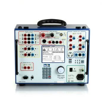
CBA 1000 circuit breaker timing test equipment is a reliable and very accurate operating device for the maintenance and commissioning of circuit breakers in medium and high voltage substation. It can perform static and dynamic contact resistance measurement and it’s an accurate timing speed and motion analyzer.
 Datasheet Datasheet |
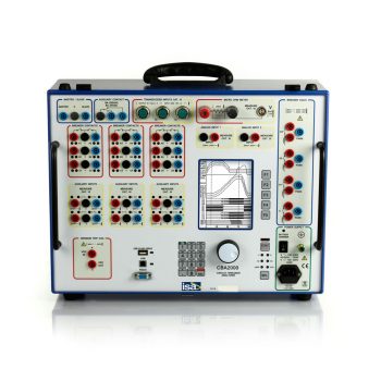
CBA 2000 diagnostic system is designed to grant the highest accuracy while testing circuit breaker. It can perform static and dynamic contact resistance measurement and it’s a precise timing speed and motion analyzer. Circuit breaker timing test set CBA 2000 is the perfect solution when a complete and reliable diagnostics has to be performed on circuit breakers.
| Datasheet |
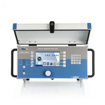
CBA 3000 allows any timing test, motion and speed analysis, multiple contemporary static and dynamic contact resistance measurements, both sides grounded (BSG) tests, undervoltage condition test and more. All these functions are integrated in a single lightweight test case without the need of connecting additional external modules.
| Datasheet |
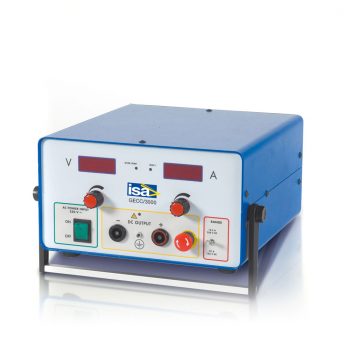
The DC voltage power supply models GECC3000 and GECC 1500 are designed for supplying the DC voltage and current for testing any type of system which requires an high-power, ripple free DC power supply
| Datasheet |
