


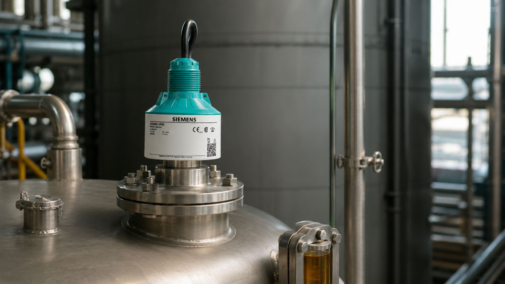
Radar level sensors operate without contact and are therefore an attractive solution for many tanks and process vessels. With water, aqueous media or other highly reflective liquids, measurement is generally relatively straightforward. It becomes more challenging with media that have a low dielectric constant, such as certain oils, fuels, hydrocarbons, solvents or liquefied gases.
The problem is not that these media do not reflect a radar signal at all. The reflection from the product surface is simply weaker. At the same time, internal structures, vessel walls, nozzles or, in particular, a metallic tank bottom can generate very strong echoes. The sensor must therefore reliably distinguish the actual level echo from all other signals.
When selecting a radar sensor, it is therefore not sufficient simply to ask:
What is the maximum measuring range?
.
At least equally important are:
- dielectric constant of the medium,
- expected strength of the product echo,
- measuring distance,
- antenna size and beam angle,
- radar frequency,
- mounting position,
- vessel geometry and internal structures,
- surface movement, foam and condensation,
- false echoes and their separation from the product echo,
- available echo reserve.
A nominal measuring range of, for example, 30 m does not automatically mean that every medium can be measured reliably over a distance of 30 m. With weakly reflective media, sufficient signal reserve must be available for the actual application.
What Does the Dielectric Constant Mean in Radar Measurement?
Radar sensors transmit electromagnetic waves towards the product surface. Part of this energy is reflected at the interface between the gas space and the medium and returned to the antenna.
The strength of this reflection depends, among other things, on the electromagnetic properties of the medium. One particularly important parameter is relative permittivity:
εr
In level measurement technology, this is often simply referred to as:
dielectric constant
or:
DK value
.
The greater the difference between the electromagnetic properties of the gas space and the medium, the stronger the reflection from the surface can be.
Water and many water-based liquids reflect radar energy strongly. Many hydrocarbons, oils and organic solvents, however, have significantly lower dielectric constants and therefore produce weaker surface echoes.
The dielectric constant is not an unchanging material property under all possible conditions. It can depend, among other things, on:
- temperature,
- composition,
- concentration,
- measurement frequency.
For changing product mixtures, the design should therefore not be based exclusively on a single tabulated value. The most unfavorable operating condition that can realistically occur is particularly important for sensor selection.
Why Low Dielectric Constants Produce Weaker Echoes
For an ideally flat interface, the approximate magnitude of the reflection can be estimated in simplified form from the difference in electromagnetic properties.
The important practical relationship is:
The closer the dielectric constant of the medium is to that of the gas space, the smaller the proportion of radar energy reflected from the product surface.
Part of the transmitted radar energy then penetrates into the medium.
This alone does not necessarily cause a measurement problem. Modern radar sensors can evaluate very small signals. However, the application becomes critical if, at the same time:
- the measuring distance is large,
- the product surface is turbulent or inclined,
- internal structures generate strong false echoes,
- the antenna is unfavorably aligned,
- the radar beam strikes the vessel wall,
- the antenna is contaminated or heavily affected by condensation,
- a highly reflective metallic tank bottom is located behind the medium.
The application must therefore be considered as a complete signal path.
What Is Echo Reserve?
The sensor must not merely receive some kind of echo. It must reliably detect the product echo and distinguish it from false echoes and the background signal.
In simplified terms, echo reserve can be understood as the margin between:
available product echo
and:
required detection threshold or interfering signals
.
The greater this margin, the more robust the measuring point is against changing conditions.
Reserve is required, for example, for:
- changing product properties,
- temperature changes,
- condensation,
- deposits on the antenna,
- turbulence,
- foam formation,
- different filling conditions,
- moving or inclined product surfaces.
The way signal quality is displayed depends on the manufacturer. Depending on the device, parameters such as echo amplitude, signal quality, signal-to-noise ratio, echo curve or other diagnostic values may be shown.
A statement such as “the sensor can just about detect the product” is therefore not sufficient for robust industrial measurement. Adequate signal reserve should still be available even under the most unfavorable operating conditions.
Why Maximum Measuring Range and Reliable Measuring Range Are Not the Same
The data sheet of a radar sensor may specify a maximum measuring range of, for example:
10 m
20 m
or:
30 m
.
This value describes the fundamental performance capability of the device under defined conditions.
However, the actually usable range of a specific measuring point also depends on how much energy is returned from the medium to the antenna.
Measurement becomes more demanding as the distance increases
The transmitted radar beam spreads out. Only part of the energy reaches the relevant product surface, and only part of the reflected energy returns to the antenna.
A very weakly reflective product in a tall vessel therefore places different demands on the sensor than the same medium in a small tank.
For critical applications, the design should therefore not follow a simple rule such as:
Tank height 18 m → select sensor with 20 m measuring range
.
The medium, antenna, vessel geometry and required echo reserve must also be taken into account.
Why Antenna Selection Is Crucial
The antenna has a major influence on how radar energy is transmitted into the vessel and how the reflected signal is received again.
A larger antenna, or an antenna with higher performance for the respective frequency, can, among other things:
- increase directivity,
- focus the radar beam more tightly,
- concentrate more usable energy on the product surface,
- reduce sensitivity to lateral false echoes.
With weakly reflective media, a higher-performance antenna design can therefore provide significantly more reserve than simply using the smallest possible process connection.
This leads to an important selection principle:
The smallest mechanically possible antenna is not automatically the best antenna.
If the process connection can be freely selected, sufficient antenna reserve should be provided particularly in applications with:
- low dielectric constant,
- large measuring distances,
- turbulent surfaces,
- complex vessel geometry.
What Role Does Radar Frequency Play?
Modern level radars often operate in the range of approximately 80 GHz. Compared with older radar systems operating at significantly lower frequencies, this allows a much more tightly focused measuring beam to be generated with a comparable antenna size.
This offers significant advantages particularly in vessels containing:
- agitators,
- heating coils,
- bracing structures,
- pipes,
- narrow vessel cross-sections,
- mounting points close to the vessel wall.
A narrower beam can be directed past such obstacles, reducing the number of potential false echoes.
With media that have a low dielectric constant, this can be particularly valuable: the weak product echo then has to compete with fewer strong interfering reflections.
However, a high frequency does not replace correct application design. A pipe or agitator located directly in the radar beam remains a potential reflector even with a highly focused sensor.
Correctly Assessing Beam Angle and Vessel Geometry
The radar beam is not an infinitely thin line. It has a defined beam angle.
As the distance from the sensor increases, the diameter of the covered area therefore increases.
In simplified form, the beam diameter can be estimated using:
D ≈ 2 × L × tan(α / 2)
.
Where:
D= approximate beam diameter,L= distance from the sensor,α= beam angle.
Example
For a radar sensor with:
4° beam angle
the theoretical beam diameter at:
10 m distance
is approximately:
0.70 m
.
This makes it possible to estimate during the planning stage whether, for example:
- a vessel wall,
- an agitator,
- a ladder,
- an inlet pipe
extends into the relevant measuring area.
The geometric beam cone is only a planning aid. Electromagnetic energy also exists outside the specified main beam. Strongly reflective components can therefore still influence the echo curve under unfavorable conditions.
Finding the Correct Mounting Position
The quality of a radar measuring point is often largely determined by the choice of mounting position.
Unfavorable positions include, for example:
- directly above the filling stream,
- immediately next to a vessel wall if the beam strikes it,
- above agitator blades,
- above highly reflective pipes,
- in very long or unsuitable mounting nozzles,
- at locations with a strongly inclined product surface.
This is particularly important with a low dielectric constant because the false echo from a metallic internal structure can easily be stronger than the actual level echo.
If several mounting positions are available, the position should therefore be selected where the entire radar beam can reach the product surface as freely as possible over the complete measuring range.
Correctly Assessing False Echoes
Typical sources of interfering reflections in tanks and process vessels include:
- nozzles,
- weld seams,
- agitators,
- heating coils,
- pipes,
- bracing structures,
- ladders,
- internal components at the tank bottom.
Modern radar sensors can suppress known stationary false echoes during parameterization or evaluate their echo curves accordingly.
However, false-echo suppression should not be used to compensate for a fundamentally poor mounting position.
The first objective should be:
best possible product echo + lowest possible false echoes
and only then:
optimize signal processing
.
Further information on parameterization can be found in the article Configuring SITRANS LR Radar: Correctly Teaching False Echoes, Near Range and Vessel Geometry.
Why Low Levels Can Be Particularly Critical
With media that have a low dielectric constant, only part of the radar energy is reflected at the product surface. Another part can penetrate into the medium.
If a metallic tank bottom is located underneath, it can reflect part of the radar energy very strongly.
The sensor may then receive:
weak echo from the product surface
and:
strong echo from the tank bottom
.
At higher filling levels, the two signals are sufficiently separated in time or distance and can generally be evaluated independently.
With only a few centimeters of liquid, however, the product echo and tank-bottom echo can move very close together.
This is one of the most demanding situations when measuring low-reflectivity liquids with radar.
Possible consequences include:
- the tank bottom being detected instead of the product surface,
- measurement jumps at low filling levels,
- premature indication of “tank empty”,
- a practically unusable measuring zone immediately above the tank bottom.
Reliable measurement close to the tank bottom should therefore explicitly be included in the design and commissioning process for such media.
Turbulence, Foam and Moving Surfaces
The dielectric constant alone does not determine the quality of the radar echo.
A smooth, horizontal liquid surface reflects a large proportion of the usable energy back towards the antenna.
With a highly turbulent or inclined surface, however, part of the radar energy is reflected in other directions.
An already weak echo can therefore become even weaker.
Typical causes include:
- agitators,
- strong inlet flow,
- gas bubbles,
- boiling media,
- wave motion,
- foam.
Foam must be considered separately. Its effect depends strongly on its structure, moisture content and the medium involved. Some types of foam are largely penetrated by radar, while others significantly attenuate or reflect the signal.
For critical applications, it should therefore not simply be assumed that radar will always “measure through foam”.
Condensation and Contamination on the Antenna
Condensation or product deposits can alter both transmission and reception of the radar signal.
This becomes particularly relevant if the measuring point already has only a limited echo reserve.
When selecting the device, the following should therefore be taken into account:
- antenna geometry,
- material,
- inclination and drainage characteristics,
- process temperature,
- cleaning options,
- resistance to the medium.
A measuring point that only just functions adequately with a clean antenna may already become unstable after several months of operation due to a thin layer of deposits.
This again illustrates why sufficient echo reserve is more important than a measurement that only functions under ideal conditions.
Echo Analysis During Commissioning
For difficult radar applications, commissioning should not end with checking the 4…20 mA output.
If the device provides suitable diagnostic functions, the actual echo curve should be examined.
Particular points of interest include:
- position of the product echo,
- amplitude or quality of the product echo,
- strongest false echoes,
- separation between useful and interfering echoes,
- behavior in the near range,
- behavior close to the tank bottom,
- changes between empty and full vessel conditions.
Ideally, more than just one filling level should be checked.
Particularly informative conditions include:
- almost empty tank,
- medium filling level,
- almost full tank,
- filling,
- emptying,
- agitator in operation,
- typical process conditions.
This makes it possible to determine whether the selected echo is tracked reliably over the entire operating range.
Practical Example: Hydrocarbon in a Process Vessel
A process vessel contains a low-reflectivity hydrocarbon-based liquid. The tank height is 8 m. The vessel contains a lateral pipe and an agitator. The vessel bottom is made of steel.
Considering only the measuring range would initially suggest:
Select a radar sensor with a range of at least 8 m
.
However, this is not sufficient for a reliable design.
Step 1: Assess the medium
Due to the low dielectric constant, a comparatively weak surface echo must be expected.
Step 2: Assess the measuring beam
An antenna or radar sensor with a sufficiently narrow beam is selected so that the lateral pipe and agitator are located outside the main beam wherever possible.
Step 3: Optimize the mounting position
The sensor is not mounted directly next to the inlet and not directly above the agitator.
Step 4: Consider low filling levels
Since part of the radar energy can penetrate the medium, the area immediately above the metallic tank bottom is checked particularly carefully.
Step 5: Check the echo reserve
During commissioning, the echo curve is recorded or checked at different filling levels.
Step 6: Teach in false echoes
Stationary reflections are specifically taken into account through device parameterization only after the mounting position has been optimized.
This approach provides considerably greater reliability than selecting the sensor solely on the basis of:
tank height + nominal measuring range
.
Considering Measurement and Overfill Protection Separately
A continuous radar sensor can provide a highly reliable level measurement. However, this does not automatically mean that the measuring point may be used as an independent overfill protection or safety function.
For critical tanks, the following therefore needs to be clarified:
- Is the radar measurement used only for process control?
- Is it also used for a high-level alarm?
- Is independent point level detection required?
- Are there SIL, WHG or other application-specific requirements?
- May the measurement and shutdown functions use the same sensor?
For an independent protective function, a separate point level switch may be required, for example.
A good radar echo does not replace a safety assessment of the complete protective circuit.
Planning Checklist for Media with a Low Dielectric Constant
- Determine the medium and the lowest expected dielectric constant.
- Define the minimum and maximum filling level.
- Determine the distance from the sensor reference point to the tank bottom.
- Record the vessel diameter and vessel shape.
- Document agitators, pipes, heating coils and other internal structures.
- Take the filling stream and expected surface movement into account.
- Assess foam, vapor, condensation and deposits.
- Geometrically check the beam angle over the entire measuring distance.
- Do not select the antenna size solely according to the smallest available process connection.
- Provide sufficient reserve relative to the nominal maximum measuring range.
- Take measuring behavior close to the metallic tank bottom into account.
- Optimize the mounting position before applying electronic false-echo suppression.
- Check the echo curve at several actual filling levels.
- Assess the measurement function and any required safety function separately.
Common Mistakes
- Comparing only the maximum measuring range: The actual echo reserve is not taken into account.
- Ignoring the dielectric constant: A weak product echo is only discovered during commissioning.
- Selecting the smallest antenna: Process connection and price are optimized, but signal reserve is unnecessarily reduced.
- Focusing only on radar frequency: An 80 GHz sensor also requires a suitable mounting position.
- Agitator in the measuring beam: A strong metallic false echo competes with the weak product echo.
- Ignoring the tank bottom: At low filling levels, the bottom echo becomes stronger than the surface echo.
- Using false-echo suppression to compensate for poor mounting: The measuring point remains unnecessarily sensitive to process changes.
- Testing only with a full tank: Problems immediately above the tank bottom remain undetected.
- Assuming the antenna will always remain clean: Deposits reduce the available reserve during later operation.
- Automatically treating process measurement as overfill protection: The requirements for an independent protective function are not checked.
Suitable Radar Level Sensors
For compact radar level measurement applications, the Siemens SITRANS LR100 series is one suitable option. The devices use 80 GHz FMCW radar and combine a narrow radar beam with high signal sensitivity. Depending on the version and application, different measuring ranges, communication interfaces and approvals are available.
For more demanding applications involving a low dielectric constant, selection should not be based solely on the nominal measuring range. Vessel height, medium, mounting position, beam angle and required echo reserve must be assessed together.
Further radar, TDR, hydrostatic, ultrasonic and other level measurement solutions can be found under Level Measurement Technology at ICS Schneider.
We provide support with sensor selection, particularly for applications involving:
- low dielectric constants,
- large measuring distances,
- narrow tanks,
- agitators and internal structures,
- critical mounting positions,
- weak or varying echoes,
- requirements for Ex or safety functions.
Conclusion
A low dielectric constant does not rule out non-contact radar level measurement. However, it reduces the strength of the signal reflected from the product surface and makes the complete measuring point more sensitive to unfavorable geometry, false echoes and process conditions.
The decisive factor is therefore not simply whether a radar sensor can nominally measure the required distance. What matters is how much echo reserve remains under the most unfavorable actual operating conditions.
A suitable antenna, the narrowest practical measuring beam, an unobstructed mounting position and careful echo analysis are particularly important for low-reflectivity media. The area immediately above a metallic tank bottom is often critical because part of the radar energy can penetrate the medium and generate a strong bottom echo.
A robust design therefore does not simply state: “The sensor has a range of 20 m.” Instead, it states: “The product echo remains clearly stronger or more reliably detectable than false echoes and signal limits over the entire measuring range and under all relevant process conditions.”
FAQ: Radar Level Measurement with a Low Dielectric Constant
Can radar measure liquids with a low dielectric constant?
Yes. Modern radar sensors can detect even very weak reflections. Whether measurement will be reliable, however, also depends on the measuring distance, antenna, vessel geometry, mounting position and process conditions.
Why does the radar echo become weaker with a low dielectric constant?
Less radar energy is reflected at the interface between the gas space and the medium. A larger proportion can penetrate into the medium. As a result, the sensor receives a weaker surface echo.
What does echo reserve mean?
In simplified terms, it is the margin between the usable product echo and the required detection threshold or competing false echoes. The greater this reserve, the more robustly the measuring point operates under changing conditions.
Is a larger radar antenna better for a low dielectric constant?
It can be advantageous because a higher-performance antenna can increase directivity and signal reserve. However, the optimum size depends on the radar frequency, process connection, measuring distance and vessel geometry.
Is 80 GHz radar generally better for weak echoes?
80 GHz radar enables particularly tight focusing of the measuring beam. This often makes it easier to avoid vessel walls and internal structures. It improves the separation of a weak product echo from interfering reflections. Nevertheless, a suitable mounting position is still required.
Why can a metallic tank bottom interfere with the measurement?
With low-reflectivity liquids, part of the radar signal can pass through the medium and be strongly reflected by the metallic tank bottom. At very low filling levels, the surface echo and bottom echo are close together and can be more difficult to distinguish.
Does the dielectric constant need to be known exactly?
Not for every application. However, for critical media and applications with limited signal reserve, it is an important design parameter. With mixtures or changing compositions, the most unfavorable expected value should be taken into account.
Can false-echo suppression compensate for a poor mounting position?
It can suppress stationary interfering reflections, but it should not be used as a substitute for good mounting. An unobstructed measuring beam and a suitable sensor position generally provide more signal reserve.
What is the best way to test a critical radar measuring point?
The echo curve or signal diagnostics should be checked at several filling levels and, where possible, under actual process conditions. Particularly important conditions include an almost empty tank, the range close to the maximum filling level, and operating states with an agitator, filling or surface movement.
Can the same radar sensor be used simultaneously for process control and overfill protection?
This depends on the required safety function, approvals and the plant risk assessment. Reliable process measurement is not automatically an independent overfill protection system. Separate point level detection may be required.