


A pressure transmitter is actually providing a stable 4…20 mA signal, yet the analog value in the PLC fluctuates. A second sensor also shows sporadic jumps, and brief communication errors occur when a solenoid valve is switched.
The 24 V supply is checked with a multimeter:
24.1 V DC
The value appears completely normal.
Nevertheless, the power supply may still be part of the problem.
A digital multimeter primarily displays a measured value for the DC voltage or, depending on the measurement function and instrument, an RMS value of the AC component. Short voltage dips, high-frequency switching spikes or the actual waveform of the ripple may remain hidden.
For systematic diagnosis, several effects must therefore be distinguished from one another:
- slow fluctuations of the 24 V DC voltage,
- periodic ripple,
- high-frequency switching noise,
- short voltage dips caused by load steps,
- interference voltages on the 0 V line,
- coupled EMC interference,
- measurement errors caused by unsuitable probe or ground connections.
A stable multimeter reading of 24.0 V therefore does not prove that the supply is sufficiently free of interference for sensitive sensor and PLC signals.
What Does Ripple Mean on a 24 V Power Supply?
An industrial power supply is intended to convert its input voltage into a DC voltage that is as constant as possible.
Ideally, the output would be:
U = 24.000 V DC
and would not change at all over time.
However, a real power supply produces a small superimposed AC voltage.
In simplified form:
u(t) = UDC + uAC(t)
Where:
UDCis the DC component,uAC(t)is the time-dependent AC or interference component.
This AC component is often referred to as:
ripple
or:
residual ripple
.
In a switched-mode power supply, its characteristic frequency depends, among other things, on the internal circuit design and switching frequency.
In addition, significantly faster spikes and interference pulses may occur.
Distinguishing Ripple from High-Frequency Noise
The terms ripple and noise are not always used identically in data sheets.
For troubleshooting, the following practical distinction is useful:
Residual ripple or ripple
A periodic or approximately periodic fluctuation of the output voltage.
It may be associated, for example, with:
- mains frequency,
- rectification,
- switching regulator frequency,
- control behavior of the power supply.
Noise or interference spikes
Short, often high-frequency voltage spikes or bursts of oscillation.
They may be caused, for example, by:
- switching processes inside the power supply,
- power semiconductors,
- solenoid valves and relays,
- frequency converters,
- motor cables,
- unfavorable cable routing.
For a reliable assessment, it must therefore be clarified what the power supply data sheet means by:
Ripple
Ripple & Noise
or:
Residual Ripple
.
What Can a Multimeter Detect?
A multimeter is very useful for the initial check.
First measure DC
Directly at the power supply output, for example:
24.08 V DC
The same measurement should then also be repeated at the most distant or most critical load wherever possible.
This can reveal, among other things:
- incorrect output voltage,
- large static voltage drop,
- overload with permanently reduced output voltage,
- poor terminals or cable connections.
Then measure AC
Many multimeters also allow an AC voltage measurement on the 24 V rail.
A measured value of, for example:
35 mV AC
can provide an initial indication of an AC component.
However, this value must not simply be compared with a value specified in the power supply data sheet as:
mVpp
.
Depending on the instrument, the multimeter determines an RMS value over a defined frequency bandwidth. An oscilloscope, on the other hand, can display peak-to-peak values and the actual waveform over time.
30 mV RMS and 30 mV peak-to-peak therefore do not describe the same signal level.
Why an Oscilloscope Is Essential for Troubleshooting
An oscilloscope does not only show the magnitude of a voltage, but also its variation over time.
This makes it possible to determine whether the interference is, for example:
- sinusoidal,
- sawtooth-shaped,
- periodic,
- pulse-shaped,
- load-dependent,
- sporadic.
A two-channel measurement is particularly useful.
For example:
Channel 1 = 24 V supply
Channel 2 = sensor signal
.
If a voltage dip on Channel 1 occurs at exactly the same time as a jump on Channel 2, this provides much stronger evidence of a connection than two multimeter measurements taken at different times.
Using AC Coupling Correctly
A typical difficulty is that a very small interference signal is superimposed on a comparatively large DC voltage.
Example:
24 V DC + 80 mV ripple
.
With DC coupling, the oscilloscope must display both the 24 V component and the small AC component at the same time.
This can result in poor vertical resolution for the ripple.
With:
AC Coupling
the DC component is blocked at the oscilloscope input.
Essentially only the AC component remains visible on the display.
The vertical sensitivity can then be set, for example, to:
20 mV/div
or:
50 mV/div
.
This makes the ripple much easier to see.
However, it is important to note that AC coupling itself has a lower cutoff frequency. Very slow voltage changes may therefore be suppressed or distorted.
For slow dips and start-up events, additional measurement using DC coupling may therefore be necessary.
Connecting the Probe and Ground Correctly
Especially with small ripple voltages, the measurement setup itself can generate a significant part of the visible signal.
A conventional oscilloscope probe with a long ground lead forms a relatively large conductor loop.
This loop can pick up electromagnetic interference.
The oscilloscope may then display:
coupled interference
instead of:
actual output interference from the power supply
.
For ripple measurements, therefore:
- keep measurement leads as short as possible,
- connect the ground or return lead directly at the measurement point,
- avoid large conductor loops,
- use a short ground spring with suitable probes,
- with differential measurement leads, route both conductors as closely together or twisted as possible.
The measurement point should also be precisely defined.
A measurement:
directly at the power supply terminals
may produce a different result from a measurement:
at the end of a 15 m sensor cable
.
Comparing Measurement Bandwidth with the Data Sheet
The measured interference voltage depends on the frequency bandwidth being considered.
The greater the bandwidth of the measuring system, the more high-frequency signal components are captured.
Therefore, a measurement with:
20 MHz bandwidth
may produce a different result from a measurement with:
100 MHz bandwidth
.
For this reason, many power supply manufacturers define a specific measurement bandwidth and sometimes also a defined measurement setup for their ripple and noise specifications.
For a correct comparison with the data sheet, these conditions must be reproduced.
The oscilloscope should therefore not automatically be operated at the maximum available bandwidth.
If it has, for example, a switchable:
20 MHz bandwidth limit
and the power supply manufacturer also specifies 20 MHz as the test bandwidth, this setting may be appropriate for comparison.
For general EMC troubleshooting, however, a wider bandwidth may be useful in order to make additional high-frequency spikes visible.
Measuring Ripple Under Real Load
A power supply should not be tested only at no load.
The output voltage and control behavior may change with the load.
Useful test points include, for example:
- no load or minimum load,
- normal machine operation,
- high continuous load,
- machine condition with maximum simultaneous load.
The most useful measurement is taken exactly under the operating condition in which the fault occurs.
A power supply may, for example, operate perfectly cleanly for long periods and only show a brief voltage dip when several loads are switched on simultaneously, such as:
- valves,
- contactors,
- HMI,
- distributed I/O modules.
Detecting Voltage Dips During Load Steps
Not every PLC fault is caused by classic ripple.
A common problem is a dynamic voltage dip.
Example
The supply voltage is normally:
24.2 V
.
When several loads are switched on, it falls for:
3 ms
to:
18.5 V
and then rises back to 24.2 V.
A conventional multimeter may not display such a short event at all.
An oscilloscope, on the other hand, can be triggered on the voltage dip.
Such events may be caused, among other things, by:
- an undersized power supply,
- high inrush current of connected loads,
- current limiting of the power supply,
- power cables that are too long or have insufficient cross-section,
- contact resistance at terminals,
- a shared supply for highly dynamic and sensitive loads.
Measuring at the Power Supply and at the Load
The most important comparative measurement is:
power supply output
versus:
supply directly at the load
.
Case 1: Interference already present at the power supply output
Possible causes include in particular:
- the power supply itself,
- power supply loading,
- input supply,
- thermal operating conditions.
Case 2: Power supply clean, load connection disturbed
In this case, the cause is more likely to be in the downstream distribution system.
Check:
- cable length,
- conductor cross-section,
- fuses,
- terminals,
- connectors,
- shared return conductors,
- EMC coupling.
The statement “the power supply delivers clean 24 V” is therefore only meaningful if it is also known what voltage actually reaches the sensitive load.
Why the 0 V Line Itself Can Cause Interference
With a 24 V power supply, attention is often focused only on the positive conductor.
For electronic signals, however, the:
0 V line
is equally important.
If, for example, the current of a solenoid valve flows through the same return conductor as a sensitive sensor, the resistance of the conductor generates a voltage:
U = R × I
.
Example
A shared cable section, including terminals, has a resistance of:
0.08 Ω
.
When a load is switched on, an additional current of:
2 A
flows.
The local 0 V potential therefore changes by:
0.08 Ω × 2 A = 0.16 V
.
The power supply itself may still be delivering a perfectly stable 24 V.
The sensor or PLC input nevertheless sees a changed reference potential.
Depending on the system design, this effect may be referred to as:
- ground shift,
- ground offset,
- common-impedance coupling.
Systematically Troubleshooting Fluctuating PLC Analog Values
If an analog value is jumping, the sensor should not be replaced immediately.
A useful measurement sequence is:
- Measure 24 V directly at the power supply.
- Measure 24 V directly at the sensor.
- Measure the voltage between sensor 0 V and PLC analog ground.
- Check the analog signal directly at the sensor.
- Check the analog signal at the PLC input.
- Compare the interference over time with machine events.
With a two-channel oscilloscope, for example, the following can be measured simultaneously:
CH1 = 24 V sensor supply
CH2 = analog sensor signal
.
Alternatively, one channel can be connected to the supply and a second channel to the potential difference between two 0 V points, provided this is safe and permissible with the measuring instrument and its input concept.
Special Considerations for 4…20 mA Sensors
A 4…20 mA transmitter transmits the measured information as current and is therefore more robust against certain voltage drops than a direct voltage signal.
However, this does not mean that the supply voltage may fluctuate without limit.
The transmitter requires a minimum operating voltage.
In addition, sufficient voltage must be available in the current loop for:
- the transmitter,
- the cable,
- the measuring resistor,
- isolators or inputs.
In simplified form:
Usupply ≥ Utransmitter,min + I × Rloop
.
If the supply drops too far during a load step, the transmitter can leave its specified operating range.
Shared 0 V paths or non-isolated inputs can also introduce additional interference.
Why 0…10 V Signals Can Be Particularly Sensitive
With a voltage signal, the measured value is transmitted directly as a potential difference.
For:
0...10 V
for example:
100 mV
already corresponds to:
1% of the full measuring range
.
A ground offset of only a few tens of millivolts can therefore already appear as a visible measurement error.
Particularly critical are:
- long cables,
- shared return conductors with power loads,
- lack of galvanic isolation,
- unfavorable shield routing,
- high interference currents.
In such systems, it is therefore not sufficient to measure only:
+24 V against 0 V
It should also be checked whether different 0 V points actually have the same potential.
Solenoid Valves, Relays and Contactors as Sources of Interference
Inductive loads can generate high voltage spikes when switched off.
These include:
- solenoid valves,
- relays,
- contactors,
- brake solenoids.
If suitable suppression is missing, the interference can enter sensor and PLC circuits via:
- supply lines,
- shared ground lines,
- capacitive coupling,
- inductive coupling.
The effect may appear on the oscilloscope as a very short pulse.
This makes it possible to distinguish whether apparent “power supply ripple” is actually originating from the power supply or is being coupled back into the 24 V rail by a connected load.
Distinguishing Ground-Referenced and Floating Measurements
With a conventional bench oscilloscope, the outer conductor or ground of many BNC inputs is connected to protective earth.
The ground clip of a normal probe must therefore not be connected arbitrarily to any point in a circuit.
If the measurement point is at a potential relative to protective earth, an incorrect connection can:
- cause a short circuit,
- alter the system,
- damage the measuring instrument,
- endanger the operator.
For measurements that are not clearly ground-referenced, suitable methods must therefore be used depending on the task, for example:
- galvanically isolated oscilloscope inputs,
- suitable differential probes,
- other approved differential measurement methods.
The protective earth conductor of a bench oscilloscope must never be removed in order to create a supposedly “floating” input.
Practical Example: Analog Value Fluctuates When a Valve Is Switched
A PLC reads a pressure transmitter with:
4...20 mA
.
During normal operation, the value is stable.
Whenever a 24 V solenoid valve is switched on, the indicated pressure briefly jumps.
Step 1: Check the DC voltage
The multimeter reads at the power supply:
24.2 V DC
.
No fault is initially apparent.
Step 2: Oscilloscope at the power supply output
The 24 V rail is examined with the oscilloscope.
During steady-state operation, only a small amount of ripple is present.
Step 3: Trigger on the switching event
When the solenoid valve is switched on, the supply voltage drops briefly.
A short high-frequency disturbance also appears.
Step 4: Measure directly at the sensor
The voltage dip at the sensor is greater than directly at the power supply.
This makes it clear that the control behavior of the power supply is not the only factor that needs to be considered.
Step 5: Check the voltage drop in the cables
The solenoid valve and the sensor partly share the same 0 V return conductor.
When switching occurs, an additional voltage drop is generated there.
Step 6: Modify the wiring
The sensor supply is given an appropriate separate cable route to the central 24 V / 0 V distribution point.
The inductive load is equipped with suitable suppression for the application.
Step 7: Repeat the measurement
The voltage dip at the sensor is significantly reduced and the PLC analog value remains stable.
The example shows:
analog value fluctuates
does not automatically mean:
sensor defective
and:
24.2 V at the power supply
does not automatically mean:
interference-free supply at the sensor
.
Systematic Test Procedure
- Measure the DC output voltage directly at the power supply.
- Check the DC voltage under the actual operating condition in which the problem occurs.
- Measure the voltage directly at the affected sensor or PLC module.
- Use a suitable multimeter to obtain an initial indication of the AC component.
- Use an oscilloscope to analyze waveform, spikes and short voltage dips.
- Use AC coupling where appropriate for ripple measurement.
- Keep probe and ground leads as short as possible.
- Set the measurement bandwidth according to the test task or data sheet specification.
- Compare the power supply output with the load connection.
- Repeat the measurement at minimum, normal and high load.
- Trigger on load steps and machine events.
- Check shared 0 V conductors for dynamic voltage drop.
- Compare sensor and PLC signals with the supply at the same time.
- Check inductive loads and their suppression circuits.
- Check the routing of signal, motor and power cables.
- For floating or non-ground-referenced measurement points, use only suitable isolated or differential measurement technology.
Common Measurement Errors
- Looking only at the DC reading of the multimeter: Short voltage dips and high-frequency interference remain hidden.
- Directly comparing an AC multimeter reading with mVpp from the data sheet: RMS and peak-to-peak values are different quantities.
- Measuring only at no load: The interference may occur only under actual operating load.
- Measuring only directly at the power supply: Cable and terminal problems between the power supply and the load remain undetected.
- Using a long oscilloscope ground lead: The measurement loop can pick up additional interference.
- Always using the maximum oscilloscope bandwidth: The result may then not be comparable with the bandwidth specification in the power supply data sheet.
- Looking only at the +24 V conductor: A dynamic voltage drop on 0 V can cause the same effect.
- Attributing every disturbance to the power supply: Connected relays, valves, motor controls or converters can feed interference back into the supply.
- Using AC coupling for slow voltage dips: Very slow voltage changes may be suppressed.
- Connecting oscilloscope ground arbitrarily: With ground-referenced inputs, this can cause a short circuit.
- Replacing the sensor immediately: The supply, reference potential and PLC input have not been checked separately.
- Confusing shielding with the return conductor: Shield, PE and 0 V have different functions and must be connected according to the system design.
Suitable Measuring Instruments and Power Supplies
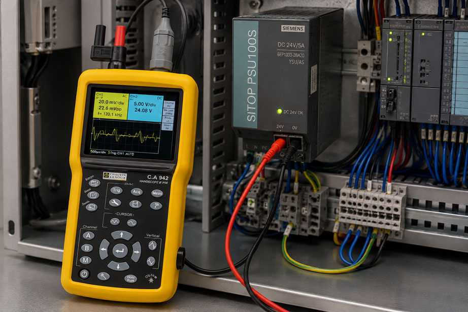
For analyzing ripple, voltage dips and fast interference signals, the CA 942 HANDSCOPE is one suitable option.
The portable instrument combines:
- 40 MHz oscilloscope,
- two isolated measurement channels,
- 2 GS/s sampling rate,
- multimeter function,
- portable design for service and maintenance.
The two channels are particularly useful for troubleshooting because the supply voltage and sensor signal, or two different supply points, can be observed simultaneously.
Further instruments for time-domain signal analysis can be found under Oscilloscopes at ICS Schneider.
For initial voltage, current and resistance measurements, digital multimeters are also available.
Suitable industrial power supplies, DC/DC converters and additional supply components can be found under Power Supply at ICS Schneider.
Further testing and diagnostic instruments for commissioning and troubleshooting can be found under Measuring Instruments for Control Cabinet Construction.
Conclusion
A measured DC voltage of 24 V is not sufficient to fully assess the quality of an industrial power supply.
Ripple, high-frequency switching spikes and short dynamic voltage dips may be superimposed on the DC voltage. These effects are often not visible with a conventional DC multimeter.
The multimeter remains a useful first test step. However, an oscilloscope is required to analyze the actual waveform over time.
The measurement setup has a major influence on the quality of the result. Short probe connections, suitable bandwidth and the correct selection between DC and AC coupling prevent the measurement setup itself from appearing as an apparent source of interference.
The measurement location is equally important. If the supply is clean directly at the power supply but disturbed at the sensor, cables, terminals and especially shared 0 V return conductors must be investigated.
Fluctuating PLC analog values can therefore be caused by the power supply itself as well as by load steps, voltage drop, ground offset or coupled interference.
The most reliable diagnosis is therefore not simply “24 V present or not”, but: How does the supply behave directly at the affected load over time and at the exact moment when the system fault occurs?
FAQ: Measuring Ripple on a 24 V Power Supply
What is ripple on a 24 V power supply?
Ripple is a small time-varying voltage component superimposed on the actual 24 V DC voltage. In switched-mode power supplies, it may be related, among other things, to the switching and control principle of the power supply.
Can I measure ripple with a multimeter?
A suitable multimeter can provide an initial indication of the AC voltage component in AC mode. However, it normally does not show the waveform and may miss short spikes or dips. An oscilloscope is more suitable for detailed diagnosis.
Why does my multimeter show 24 V even though the PLC has faults?
A multimeter averages or processes the signal over a certain measurement time. A voltage dip lasting only a few milliseconds may therefore remain hidden. In addition, the supply may be stable directly at the power supply while a different voltage is present at the PLC module due to cable losses.
How do I measure ripple with an oscilloscope?
Measure between +24 V and 0 V at the relevant measurement point. For small AC components, AC coupling can be helpful because it suppresses the large DC component. Measurement leads should be kept as short as possible and the bandwidth must match the test task.
What does mVpp mean?
mVpp, or mV peak-to-peak, describes the difference between the highest and lowest instantaneous values of the interference voltage. This value must not be directly equated with an RMS value from a multimeter.
Why should ripple be measured under load?
The control behavior of a power supply can change with output load. Dynamic loads can also cause brief voltage dips when switched on or off. Measurements should therefore be carried out under exactly the operating conditions in which the fault occurs.
Can a solenoid valve cause interference on the 24 V rail?
Yes. In addition to the extra inrush current, an inductive load can generate voltage spikes when switched off. Suitable suppression and clean cable routing are therefore important.
Can a poor 0 V connection influence the PLC analog value?
Yes. If sensor and load currents flow through a shared return conductor, its resistance produces a load-dependent voltage drop. This can shift the reference potentials of the sensor and PLC relative to one another.
Are 4…20 mA signals insensitive to supply fluctuations?
They are more robust against certain cable and voltage drops than direct voltage signals. However, the transmitter still requires sufficient supply voltage and can leave its permitted operating range if the voltage dips too far.
Why is a 0…10 V signal often more sensitive?
With a voltage signal, the measurement information is transmitted directly as a potential difference. A ground offset of 100 mV, for example, already corresponds to 1% of the full range of a 0…10 V signal.
Can I simply connect the ground clip of a bench oscilloscope to 0 V?
Only if it has been clearly established that this is permissible with the grounding and potential structure of the system and with the input concept of the oscilloscope. With a conventional bench oscilloscope, probe ground is often connected to protective earth. Suitable isolated inputs or differential probes must be used for floating measurements.
What should I check first if a PLC analog value fluctuates?
First check the supply voltage and signal directly at the sensor and then at the PLC input. Next, investigate 0 V potential differences, load steps, cable routing and timing relationships with switching loads.