


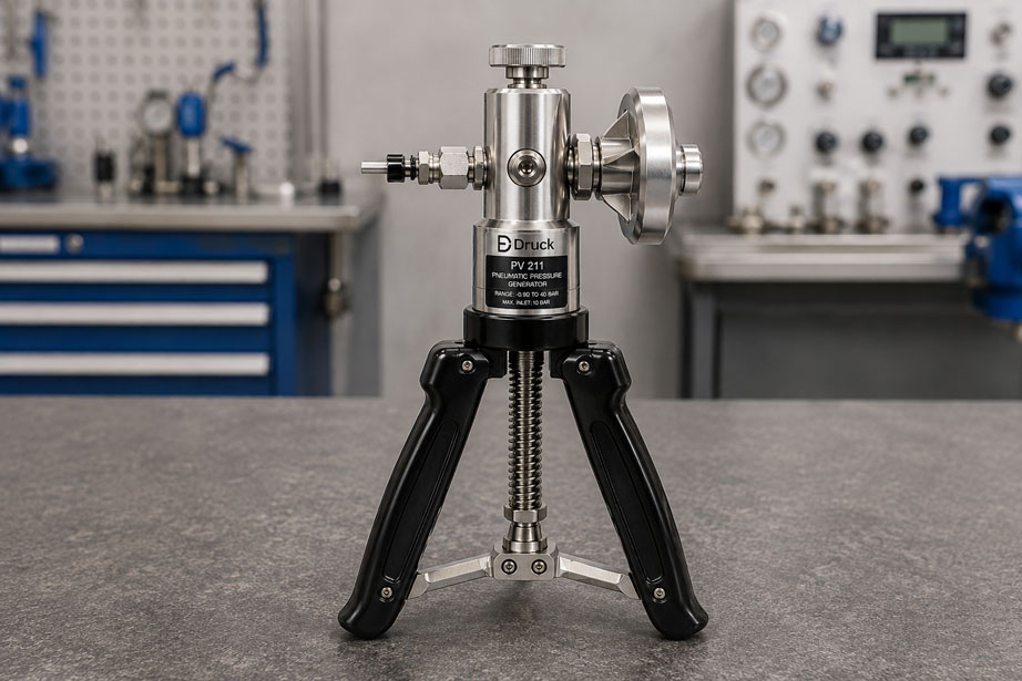
A hand-operated test pump is pressurized to 10 bar, the fine adjustment valve is no longer moved, and yet the reference pressure gauge slowly drops to 9.8 bar. Is the calibration pump leaking?
Not necessarily.
A falling or drifting test pressure can be caused by an actual leak. However, possible causes also include thermal effects, trapped air, settling seals, an elastic test hose, a relief valve that is not fully closed, or even the connected device under test itself.
At higher accuracy requirements, additional influences become visible that are barely noticeable during a simple functional test. These include, for example:
- temperature changes of the test medium,
- different elevations of the reference and device under test,
- large trapped volumes,
- elastic hoses and diaphragms,
- hydraulic circuits that have not been sufficiently vented,
- insufficient stabilization times.
For this reason, an unstable test pressure should not be investigated by randomly tightening all connections. A systematic troubleshooting approach in which the pressure circuit is reduced step by step is much faster.
The most important principle is: first determine whether gas or liquid is actually escaping from the test circuit, or whether only the pressure of a closed system is changing due to temperature, volume changes or mechanical settling effects.
Leak or Normal Pressure Drift?
A pressure change is often immediately interpreted as a leak.
However, this is too simplistic.
In a closed test circuit, the pressure depends, among other things, on:
- the medium,
- temperature,
- trapped volume,
- elasticity of the components,
- movement of diaphragms and seals.
During a pneumatic test, the air is compressed and heated during rapid pressurization. After pumping, it releases heat to the pump, hose, adapters and surroundings. The temperature decreases, and the pressure may therefore also decrease.
This pressure drop can look like a leak even though the test circuit is completely closed.
Seals and elastic components can also initially settle or deform slightly after a pressure change.
Typical indication of thermal stabilization
The pressure drops relatively clearly immediately after pumping, then the rate of change becomes smaller and the value stabilizes.
Typical indication of a leak
The pressure continues to fall even after sufficient stabilization time.
This distinction is not absolute, but it provides an important first indication.
Why Pneumatic Pressure Initially Drops After Pumping
With a pneumatic hand pump, air is mechanically compressed.
The rapid process initially causes a temperature increase.
In simplified form, the ideal gas equation describes the relationship:
p × V = n × R × T
.
If the amount of substance and volume remain approximately constant, the pressure changes with the absolute temperature.
After pressure generation, the compressed air cools back towards ambient temperature.
The result:
pressure decreases
.
With a high-resolution reference instrument, this change can be clearly visible.
Therefore:
After a significant pressure change, the final calibration value should not be read immediately.
The system should first be allowed to stabilize thermally and mechanically.
Only then should the required test point be readjusted using the fine adjustment.
Repeated rapid pumping can even prolong stabilization because every pump stroke introduces additional thermal energy into the test circuit.
Systematically Reduce the Test Circuit
The most efficient troubleshooting method is to simplify the test circuit step by step.
A complete setup may, for example, consist of:
calibration pump → reference → adapter → hose → adapter → device under test
.
Every additional connection is a potential source of leakage or additional volume.
Step 1: Pump and reference
Initially, only the reference measuring instrument is connected directly to the pump.
The device-under-test connection is closed with a suitable pressure-rated blanking plug.
If the pressure is now stable, the problem is probably not within the main body of the pump.
Step 2: Add the hose
The intended test hose is then connected and closed again at its end.
If the behavior now changes significantly, the following in particular should be checked:
- hose,
- quick couplings,
- adapters,
- seals.
Step 3: Connect the device under test
Only then is the actual device under test reintroduced into the pressure circuit.
If the pressure drop only begins at this stage, the device under test itself or its process connection is probably part of the cause.
Using this process of elimination, a complex test setup becomes a series of small, clearly testable sections.
Check the Relief Valve First
One of the most common causes of slowly falling pressure is a relief or bleed valve that is not fully closed.
This valve connects the test circuit in a controlled manner to the atmosphere or, in hydraulic systems, to the low-pressure side or reservoir.
Even a very small remaining opening can cause the pressure to decay slowly.
Check the following:
- Is the valve fully closed?
- Was it merely brought into light contact, or actually closed according to the operating instructions?
- Is there dirt on the valve seat?
- Is the sealing surface damaged?
- Has the valve seal aged?
The valve should not be tightened with excessive force.
A needle valve seals against a small, defined sealing surface. Excessive operating force can damage the seat or needle and may even make the problem worse over time.
Check Pressure/Vacuum and Selector Valves
Pneumatic combination pumps often have a selector between:
pressure
and:
vacuum
.
Hydraulic high-pressure pumps may also have a selector between rapid pre-filling and high-pressure generation.
If such a valve is not clearly in the intended position:
- pressure generation may become inefficient,
- the achievable maximum pressure may decrease,
- an internal connection may exist between different pump chambers,
- the pressure may fall again after a pump stroke.
Selector mechanisms should always be operated according to the operating instructions and only at the pressure condition specified for the device.
With many pressure/vacuum pumps, the test circuit must first be depressurized before switching modes.
Correctly Assess the Internal Check-Valve Function
During a pump stroke, a hand pump must draw in medium and then deliver it towards the test circuit during the next part of the stroke.
To achieve this, the pump mechanism requires a directional valve function. Depending on the design, internal valve seats, balls, springs or other check-valve elements perform this task.
If this function no longer works reliably, pressure that has already been generated may partially flow back into the pump chamber.
Typical symptoms may include:
- the pump generates only a small amount of pressure with each stroke,
- part of the pressure disappears immediately after the stroke,
- an unusually high number of pump strokes is required,
- the maximum achievable pressure is significantly below the normal value,
- pump performance varies between individual strokes.
Possible causes include:
- dirt particles on the valve seat,
- worn sealing elements,
- damaged valve seats,
- unsuitable or contaminated medium,
- ageing after long periods of use.
Internal valves should not be disassembled without the appropriate service instructions. In high-quality calibration pumps, certain connections may be factory-adjusted and sealed.
Check Adapters, Threads and Sealing Points
A large proportion of apparent pump faults occur outside the pump itself.
Typical leak points include:
- threaded adapters,
- quick couplings,
- hose connections,
- sealing cones,
- O-ring seals,
- flat seals,
- threads used with an unsuitable sealing principle.
It is particularly important to distinguish between different thread and sealing systems.
A:
G 1/4
parallel thread, for example, normally does not seal through the thread itself, but via a defined sealing surface.
A tapered:
1/4 NPT
thread uses a different sealing principle.
Adapters must therefore not be selected solely on the basis of whether they can be screwed together mechanically.
Thread type, sealing surface and approved sealing material must be compatible.
Correctly Assess O-Rings and Seals
A seal may appear undamaged externally and still no longer seal reliably.
Check in particular for:
- cuts,
- crushing,
- cracks,
- hardening,
- permanent deformation,
- swollen elastomers,
- contamination on the sealing surface.
The test medium used is also important.
Not every elastomer is compatible with every oil, solvent or process medium.
If process medium from a device under test enters the calibration pump, it can not only contaminate the measurement but also attack internal seals.
Before replacing a seal, check:
- which sealing material is specified,
- which dimensions are required,
- which medium is approved,
- whether an original service or seal kit is available.
Check Fine Adjustment and Volume Regulator
The fine adjustment of a calibration pump changes the trapped volume of the test circuit.
For pneumatic pumps, in simplified terms:
reduce volume → increase pressure
and:
increase volume → reduce pressure
.
In hydraulic systems, a volume regulator also allows very precise adjustment of the test pressure.
Problems can occur if:
- the fine adjustment is already at its end stop,
- its usable adjustment range has already been completely used before pressure generation,
- the spindle seal is leaking,
- the spindle is mechanically damaged or contaminated.
Before coarse pressure generation, the fine adjustment should therefore be placed in a suitable starting position so that sufficient adjustment range remains available in both directions afterwards.
A fine adjuster must not be forced beyond its intended operating range.
Why the Test Hose Can Affect Pressure
A hose is not a perfectly rigid component.
Under pressure, it may expand slightly.
This increases the volume of the test circuit and may initially cause the pressure to fall slightly.
The effect increases with:
- long hoses,
- large internal diameter,
- elastic hose material,
- high test pressure.
In highly sensitive pneumatic measurements, even the mechanical movement of a flexible hose can cause a visible pressure change.
For precise calibrations, a test setup that is:
- as short as possible,
- pressure-resistant,
- low in internal volume
is therefore advantageous.
Rule Out the Device Under Test as a Source of Leakage
A stable pressure circuit can only be expected if the device under test is also leak-tight.
With a pressure transmitter, this is often uncritical.
The situation may be different, for example, with:
- pressure switches,
- mechanical pressure gauges,
- valves,
- regulators,
- diaphragm seal systems,
- larger process assemblies.
A device under test may contain a larger internal volume, a flexible diaphragm or an actual leak.
The pump should therefore first be tested with a blanking plug.
If it remains stable in this condition, the device under test can then be included separately in the troubleshooting process.
Correctly Vent Hydraulic Pumps
During hydraulic calibration, the test circuit should be filled as completely as possible with liquid.
Liquids are only slightly compressible compared with gases.
However, if an air bubble remains trapped in the system, this area behaves like a small pneumatic spring.
Possible consequences include:
- unusually large fine-adjustment travel,
- spongy adjustment behavior,
- slow pressure generation,
- pressure changes after adjustment,
- poor repeatability.
Air is particularly likely to remain trapped in:
- high hose loops,
- adapters,
- large internal cavities of the device under test,
- lines that have not been completely filled.
The test circuit should therefore be filled and vented in accordance with the pump instructions before the actual calibration begins.
Temperature Effects on Pressure Stability
Temperature affects more than just pneumatic test circuits.
In hydraulic systems, the following also change with temperature:
- density of the medium,
- volume of the medium,
- volume of the hose and test components,
- elasticity of the seals.
In a largely closed hydraulic test circuit, even small temperature changes can therefore cause visible pressure changes.
Typical heat sources include:
- hand warmth,
- sunlight,
- cold devices under test from storage,
- warm process equipment,
- rapid hydraulic compression.
For precise calibrations, the reference, device under test and test medium should be given sufficient time to adapt to ambient conditions.
After a significant pressure change, an appropriate stabilization time should also be observed.
Height Difference Between Reference and Device Under Test
In liquid-filled test circuits, the height difference between the reference measuring point and the device under test has a real effect on pressure.
The hydrostatic pressure difference is:
Δp = ρ × g × Δh
.
Where:
ρ= density of the test medium,g= gravitational acceleration,Δh= height difference.
Example with water
At approximately:
1 m height difference
a pressure difference of about:
0.098 bar
occurs.
Even:
10 cm
therefore corresponds to approximately:
9.8 mbar
.
For a highly accurate low-pressure calibration, this is by no means negligible.
For oil, the value is slightly lower due to its lower density.
The reference and device under test should therefore be positioned as close as possible to the intended reference height, or the hydrostatic height difference should be corrected mathematically.
Systematically Locate Leaks
Once it has been confirmed that an actual leak is present, it should be located section by section.
Recommended sequence:
- Test the pump only with the reference and the device-under-test connection sealed.
- Add the hose and seal its end.
- Add adapters individually.
- Connect the device under test last.
- Use the same pressure point and the same stabilization time after each step.
For suitable pneumatic applications, an approved leak-detection method can be used on external connections.
Care must be taken to ensure that no unsuitable test medium enters:
- the calibration pump,
- the reference sensor,
- sensitive pressure connections.
For very small leaks, a time-based pressure-decay test is often more informative.
Example:
After the stabilization phase, record:
p0 = pressure at the start
and after a defined period:
p1 = pressure at the end
.
The observed pressure loss is:
Δp = p0 - p1
.
It is important that temperature and the test setup remain as constant as possible during this comparison.
Why Low-Pressure Measurements Are Particularly Sensitive
At low pressure ranges, small volume changes have a particularly noticeable effect on the measured value.
Typical disturbances include:
- movement of the hose,
- touching a hose with a warm hand,
- temperature changes of the trapped air,
- small leaks,
- diaphragm movement of the device under test,
- drafts or changes in ambient pressure at very small gauge or differential pressures.
A test setup that appears completely stable at 20 bar can therefore appear significantly unstable at only a few millibar.
For very low pressure ranges, specially designed low-pressure sources and low-volume connections are generally more suitable than a universal high-pressure hand pump.
Special Considerations for Hydraulic High Pressure
At several hundred bar, even very small volume changes become relevant.
Components that may deform elastically include:
- hose,
- adapters,
- seals,
- measuring cells,
- device-under-test housings.
After the initial pressure build-up, a slight pressure drop may therefore occur even though no medium is visibly escaping.
The system is initially mechanically loaded and settles.
For hydraulic high-pressure calibration, it is therefore advisable to approach the pressure in a controlled manner, allow a stabilization period, and then readjust using the volume or fine regulator.
A permanently rapid or large pressure decrease should nevertheless be investigated for leakage, trapped air or a technical defect.
Practical Example: 20-Bar Transmitter Cannot Be Calibrated Stably
A pressure transmitter with a measuring range of:
0...20 bar
is to be calibrated pneumatically using a hand-operated test pump.
At:
15 bar
the reference reading falls within a short time to:
14.8 bar
.
Step 1: Allow stabilization
The pressure is generated again and is initially not readjusted.
The rapid initial drop becomes significantly slower after a short period.
This already suggests a thermal component.
Step 2: Isolate the pump
The transmitter is removed and the device-under-test connection is safely sealed.
The test circuit now remains almost constant after the stabilization phase.
The pump itself is therefore probably not the main cause.
Step 3: Check the hose
The hose is connected separately and sealed at the end.
This setup also remains stable.
Step 4: Check the device-under-test adapter
A damaged seal is found on the transmitter adapter.
After replacing it with the correct seal, the device under test is connected again.
Step 5: Calibrate
The desired pressure point is approached approximately with the pump.
After a short stabilization period, the test point is set precisely using only the fine adjustment.
Only then are the reference and device-under-test readings documented.
The example shows why:
pressure drops = pump defective
is not a reliable diagnosis.
When Maintenance or Seal Replacement Is Advisable
Pump maintenance becomes more likely if:
- the pressure cannot be maintained even with a blanking plug,
- relief and selector valves are correctly set,
- external adapters and seals have been ruled out,
- the pump stroke loses significant effectiveness,
- the maximum achievable pressure drops significantly,
- visible or audible internal leakage occurs,
- seals are hardened or damaged.
Many professional calibration pumps can be serviced using dedicated service or seal kits.
Only the replacement kit intended for the specific pump version should be used.
Factory-adjusted or factory-sealed assemblies should not be retightened or disassembled without approval.
Testing and Troubleshooting Checklist
- Check whether the observed pressure drop occurs only immediately after pumping or continues permanently.
- Allow sufficient stabilization time after a significant pressure change.
- Set the fine adjustment to a sensible mid-position before generating pressure.
- Close the relief valve fully without excessive force.
- Check the pressure/vacuum or operating-mode selector.
- Initially test the pump only with the reference and a blanking plug.
- Then add the hose separately and seal it.
- Check adapters and sealing points individually.
- Reconnect the device under test only at the end.
- Check O-rings and seals for damage, contamination and material compatibility.
- Completely remove air from hydraulic systems.
- Keep hose volume and hose elasticity as low as possible.
- Take temperature changes of the medium, pump, device under test and reference into account.
- For liquid calibrations, consider the height difference between reference and device under test.
- Always assess pressure loss after a comparable stabilization time.
- Service internal pump components only in accordance with the intended service instructions.
Common Mistakes
- Immediately assuming a leak: The pressure may initially fall simply due to cooling of the compressed air.
- Constantly pumping again: This repeatedly restarts the pneumatic temperature stabilization process.
- Not fully closing the relief valve: Even a very small remaining opening causes continuous pressure loss.
- Closing the valve with excessive force: This can damage the needle or valve seat.
- Tightening all connections at the same time: The actual source of the problem can no longer be clearly identified afterwards.
- Using the wrong sealing principle: Parallel and tapered threads are combined without the appropriate seal or sealing method.
- Not ruling out the device under test: A leak in the device under test is incorrectly attributed to the pump.
- Leaving air in the hydraulic circuit: The pressure behaves spongily and is difficult to stabilize.
- Fine adjustment already at the end stop: No adjustment travel remains for precise setting of the actual test point.
- Using a very long hose: Additional volume and hose expansion impair controllability.
- Ignoring height difference: With liquids, a real hydrostatic pressure difference occurs.
- Underestimating hand warmth: Particularly small trapped volumes can already react to minor temperature changes.
- Retightening factory connections: Sealed pump assemblies can be damaged as a result.
Suitable Calibration Pumps
For pneumatic pressure and vacuum calibrations, the Druck PV211 is one suitable option.
The hand pump provides:
- pneumatic pressure generation up to 40 bar,
- vacuum generation down to approximately -900 mbar,
- pressure and vacuum operation,
- fine adjustment of the test pressure,
- controlled pressure release via a needle valve.
The clearly structured pneumatic test circuit is particularly useful during troubleshooting. The device under test, hose and adapters can be disconnected step by step in order to distinguish an external leak from a problem inside the pump.
For hydraulic high-pressure applications, the Druck PV212 provides a solution for pressures up to 700 or 1,000 bar.
The PV212 features, among other things:
- hydraulic pressure generation,
- 100 ml reservoir,
- fine adjustment,
- operation with suitable mineral oil or distilled water,
- optional pressure relief valves.
Further pneumatic and hydraulic pressure sources, reference instruments and complete calibration solutions can be found under Calibration Equipment at ICS Schneider.
Conclusion
A falling test pressure does not automatically mean that the calibration pump is defective.
In pneumatic systems, cooling of the compressed air immediately after pressure generation can already cause a visible pressure change. Seals, hoses and devices under test may also settle mechanically.
If the pressure loss remains after sufficient stabilization, the test circuit should be systematically reduced. First, the pump is tested with the reference and a blanking plug, then the hose, adapters and finally the device under test are added.
Particular attention should be paid to the relief valve, selector function, seals, connections and the internal check-valve function of the pump.
For hydraulic testing, complete venting and hydrostatic height difference must also be considered. Even a few centimeters of height difference can be relevant in precise low-pressure measurements.
The most reliable troubleshooting method is therefore not to tighten as many components as possible at the same time, but to simplify the test circuit in a controlled manner and check each possible cause individually.
FAQ: Pressure Calibration Pump Does Not Hold Pressure
Why does the pressure drop immediately after pumping?
With pneumatic pumps, the air heats up during compression. After pumping, it cools down again and the pressure decreases. Seals, hoses and other elastic components may also initially settle. A stabilization period should therefore be observed before the final adjustment.
How can I determine whether the calibration pump itself is leaking?
Connect only the reference measuring instrument and close the device-under-test connection with a suitable blanking plug. If the pressure remains stable after the stabilization phase, the cause is probably in the hose, adapter or device under test.
Can a relief valve that is not fully closed cause the pressure drop?
Yes. Even a very small opening at the relief valve can cause continuous pressure loss. The valve should be closed according to the operating instructions, but not tightened with excessive force.
Why does the hand pump suddenly generate hardly any pressure?
Possible causes include an incorrect valve position, leaking external connections, damaged seals, excessive test volume or an impaired internal check-valve function. The test circuit should initially be kept as small as possible.
Why does a hydraulic calibration pump have to be vented?
Trapped air is significantly more compressible than the test liquid. An air bubble therefore behaves like an elastic volume and causes spongy pressure adjustment, greater adjustment travel and poor stability.
Can the test hose cause a pressure drop even if it is leak-tight?
Yes. A flexible hose can expand slightly under pressure. This increases the trapped volume and may initially cause the pressure to fall. The effect increases with hose length, internal volume and test pressure.
Can the device under test itself be the cause?
Yes. A device under test may leak or cause additional volume changes due to diaphragms and larger internal volumes. The pump should therefore first be tested without the device under test.
Why is the fine adjustment important before pumping?
It should be positioned so that sufficient adjustment travel remains for both increasing and decreasing pressure after coarse pressure generation. If it is already at its end stop, the test point can no longer be adjusted cleanly.
Does the height difference between the reference and device under test matter?
With gaseous test media, the effect is usually very small in typical test setups. With liquids, however, it can be significant. With water, a height difference of 10 cm corresponds to approximately 9.8 mbar of pressure difference.
Why does hydraulic pressure change when the temperature changes?
The test medium, hose, seals and connected components change their volume with temperature. In a closed hydraulic system, even small temperature changes can therefore cause visible pressure changes.
When should the seals of a hand pump be replaced?
If external leak points have been ruled out and the pump continues to lose pressure, the pump stroke loses effectiveness, or the seals are visibly damaged or hardened, the specified service or seal kit may be required.
Should I retighten internal pump connections?
Not without corresponding manufacturer approval. Some connections are factory-adjusted and sealed. Unauthorized retightening or disassembly can damage the sealing point and make servicing necessary.