


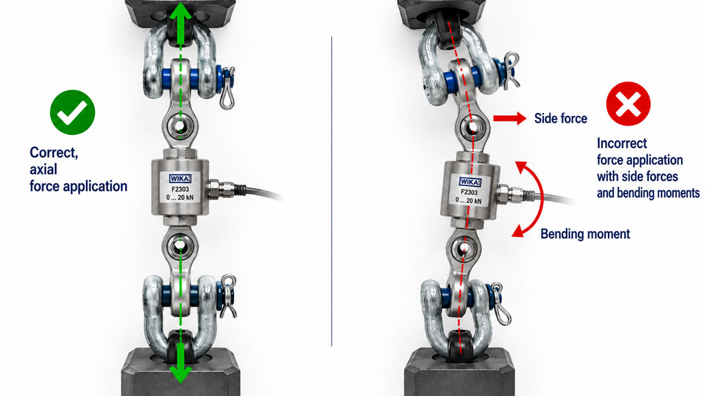
A tensile load cell is installed in a test rig and displays a plausible value under a known load. However, after modifying a mounting bracket, replacing a shackle or changing the pulling direction, a deviation occurs. The sensor itself has neither been electrically modified nor overloaded. Nevertheless, the results differ because the force is no longer applied under the same mechanical conditions.
In tensile force measurement, the entire connection between the loaded components determines the quality of the measurement result. Shackles, rod ends, pins and tension rods should transmit the force as closely as possible along the intended measurement axis. Lateral offsets, misaligned connections and restricted joint movement, on the other hand, can generate transverse forces, bending moments and mechanical stresses. An electrically functioning load cell can therefore produce an erroneous signal.
This technical article explains how tensile force measurement chains should be mechanically designed and tested. It focuses on the differences between shackles and rod ends, the effects of side loads and bending moments, the selection of suitable load cells, and the assessment of dynamics, signal processing and calibration. The decisive factor is not only how much force is applied, but also how that force reaches the sensing element.
Table of Contents
- Define the Measurement Task and the Actual Force Quantity
- Understand the Complete Force Path Through the Measurement Chain
- Distinguish Between Shackles, Rod Ends and Clevis Connections
- How Side Loads and Bending Moments Arise
- Calculation Example: Angular Misalignment and Eccentric Force Application
- Select the Correct Load Cell Design
- Apply Loads Correctly to Shackles and Pins
- Use Rod Ends for Controlled Alignment
- Check Alignment, Bearings and Installation Geometry
- Account for Threaded Connections, Preloads and Assembly Forces
- Distinguish Rated Force, Overload and Permissible Working Load
- Assess Dynamic Tensile Forces, Vibrations and Shock Loads
- Evaluate Rope Routing, Deflection and Changing Pulling Directions
- Understand Strain Gauge Measurement and Unwanted Load Components
- Design Signal Conditioning, Amplification and Data Acquisition
- Check Zero Point, Settling Behaviour and Mechanical Hysteresis
- Calibrate Load Cells Using a Suitable Reference
- Verify the Complete Measurement Chain in Its Installed Condition
- Assess Measurement Uncertainty and Installation Effects Separately
- Systematically Diagnose Typical Measurement Deviations
- Suitable Force Measurement Technology from ICS Schneider
- Conclusion: Force Application Is Part of the Measurement System
- Frequently Asked Questions About Tensile Force Measurement with Shackles and Rod Ends
1. Define the Measurement Task and the Actual Force Quantity
Tensile force measurement can serve different purposes. In a test rig, the force acting on a specimen may need to be measured. On a cable winch, the current rope tension may need to be monitored. In a lifting application, tensile force measurement may form part of a load monitoring system. Although forces are measured in all these cases, the mechanical boundary conditions differ considerably.
Before selecting the sensor, it must therefore be established which force is actually to be measured. For an ideally axially loaded tensile load cell, the measured quantity corresponds to the force along its intended measurement axis. This is not necessarily identical to an external total force, the resultant force in a rope system or the weight of a suspended load.
It is particularly important to distinguish between measurements for process monitoring, materials testing and safety-related load monitoring. The latter two applications may involve additional requirements concerning measurement uncertainty, traceability, permissible loads and safety functions. The mechanical suitability of the complete force path must be demonstrated independently of the sensor’s electrical accuracy.
A clearly defined measurement task therefore specifies more than the expected maximum tensile force. It also describes the direction, time-dependent behaviour, frequency of load cycles, possible impacts and whether the connected components can move during measurement.
2. Understand the Complete Force Path Through the Measurement Chain
The force path begins at the point where the tensile force originates and ends at the mechanical reaction support. Several connecting elements may be located between these points. Each of these elements can potentially affect the mobility, stiffness and spatial alignment of the connection.
A basic arrangement for an axially loaded tensile load cell may look as follows:
Fixed reaction support → suitable articulated or pinned connection → load cell → suitable articulated or pinned connection → loaded component
The connecting elements actually required depend on the load cell design. An S-type sensor with threaded connections requires a different force application arrangement from a load link with pin holes. A load cell with an integrated rod end must also be considered in relation to its intended installation geometry.
For the analysis, the line of force is traced from the load application point to the reaction support. It should pass as closely as possible through the load cell’s intended measurement axis. If the force is applied eccentrically or deflected laterally by a rigid connection, additional stresses may arise.
An important distinction must be made between a change in the orientation of the entire measurement chain and incorrect loading of the sensor. A freely moving, fully aligned measurement chain can still be correctly loaded axially even when positioned at an angle to the vertical. Problems arise when the direction of the applied force deviates from the sensor axis or movement is restricted by the connections.
3. Distinguish Between Shackles, Rod Ends and Clevis Connections
Shackles and rod ends are frequently used together with tensile load cells. However, their mechanical functions differ. A shackle connects components using a bow and a pin. A rod end contains a bearing that permits angular movement between connected parts within its design limits.
Both components can contribute to favourable force application. However, neither guarantees that the sensor will be loaded without transverse forces.
| Connecting Element | Mechanical Function | Important Inspection Point |
|---|---|---|
| Shackle with pin | Connects tensile members and permits certain relative movements depending on the geometry and mating component | Permissible loading direction, pin loading, centring and load capacity |
| Rod end with spherical bearing | Permits limited angular movement between connected components | Angular movement range, bearing load, friction and alignment of the force line |
| Clevis with pin | Transmits force through an articulated pin connection | Central load distribution, pin diameter, bearing clearance and direction of movement |
| Rigid tension rod | Transmits tensile forces between fixed connection points | Alignment, thread engagement and possible mechanical stress |
| Load link | Measures force directly as a load-bearing connecting element | Correct loading of the designated pin holes and measurement direction |
The permissible directions of movement are determined by the particular connection. A simple pinned joint may allow rotation about its pin axis, but cannot compensate for arbitrary angular misalignments in three dimensions. A rod end with a spherical bearing provides additional angular mobility, although its limits must be respected.
All relevant degrees of freedom should therefore be considered during design. The connection must permit the movements required during operation without allowing uncontrolled displacement or creating unfavourable additional loads.
4. How Side Loads and Bending Moments Arise
A pure tensile force loads the sensing element along its intended axis. If the force direction deviates from this axis, the external force can be resolved into an axial component and a component acting transversely to the measurement axis.
For the angle α between the force vector and the sensor axis:
Faxial = F · cos(α)
Ftransverse = F · sin(α)
These equations initially describe only the geometric resolution of the external force. How the load cell responds to the transverse component depends on its design and the actual bearing and support conditions. A universally applicable measurement deviation therefore cannot be calculated from angular misalignment alone.
A bending moment can arise when the force is applied at a lateral distance e from the intended measurement axis. For the simplified case of a force acting parallel to the axis but applied eccentrically:
M = F · e
Here, M denotes the bending moment, F the applied force and e the perpendicular distance between the force line and the reference axis.
Transverse forces and bending moments may occur simultaneously, but do not necessarily have the same cause. For example, a rope pulling at an angle can generate a transverse force. An off-centre pin can create an additional moment. A rigid threaded connection can also introduce mechanical constraint forces into the measurement chain, even when no external useful load is applied.
The consequences range from altered readings and poorer repeatability to locally increased stresses or permanent damage. A sensor with a high accuracy class is not automatically protected against such influences.
5. Calculation Example: Angular Misalignment and Eccentric Force Application
An idealised example considers a tensile force of 20 kN. The force acts at different angles relative to the intended sensor axis. Resolving the force geometrically gives the following components:
| Angle to Sensor Axis | Axial Component | Transverse Component | Assessment |
|---|---|---|---|
| 0° | 20.00 kN | 0.00 kN | Ideal axial force direction |
| 2° | 19.99 kN | 0.70 kN | Already a significant transverse component |
| 5° | 19.92 kN | 1.74 kN | Additional loading must be assessed |
| 10° | 19.70 kN | 3.47 kN | Significant deviation from the axial loading direction |
The table shows that even small angular misalignments can produce significant transverse forces. At 5° and an external tensile force of 20 kN, the transverse component is already approximately 1.74 kN. However, this does not mean that the load cell must display exactly 19.92 kN. The reading depends on its transverse sensitivity, the actual force application and the mechanical behaviour of the complete measuring arrangement.
A second example considers a lateral offset of 5 mm with a force of 20 kN acting parallel to the measurement axis:
F = 20,000 N
e = 0.005 m
M = 20,000 N · 0.005 m = 100 Nm
The simplified model produces a bending moment of 100 Nm. Whether this moment actually acts on the sensitive measuring element depends on the support conditions and connecting elements. A suitable articulated arrangement can reduce unfavourable moments, whereas rigid or misaligned connections can transmit them.
Both examples are purely mechanical calculation models and do not represent permissible operating limits of a particular load cell. However, they demonstrate why small geometric deviations in a heavily loaded measurement chain must not be neglected.
6. Select the Correct Load Cell Design
The design of the load cell largely determines how the load must be applied. An S-type sensor generally has two opposing threaded connections. It is suitable for tensile and compressive force measurement provided that force application meets the relevant design requirements. Rod ends or suitable clevis connections can help achieve favourable axial loading.
A cylindrical tension/compression load cell with an integrated rod end allows a different type of mechanical integration. The rod end can permit angular movement and thereby reduce mechanical stress. The decisive factor remains whether the complete measurement chain directs the force along the measurement axis under the intended conditions.
Load links, on the other hand, have pin holes and are integrated directly into the force path as load-bearing connecting elements. They are used, for example, in cable winches, lifting equipment and industrial tensile applications. Their bearing and pin geometry forms part of the measurement system. An unsuitable pin contact surface can change the load distribution.
A load pin, in turn, measures loading within a pin or bearing arrangement. It is not an interchangeable replacement for an axial tensile load cell, because its measured quantity and calibration relate to a different force application arrangement. The decision between these designs must therefore be based on the actual machine geometry.
For every configuration, rated force, permissible additional loads, mechanical interfaces, required output signal and dynamic suitability must also be checked. Better electronic resolution cannot compensate for a mechanically unsuitable design.
7. Apply Loads Correctly to Shackles and Pins
Shackles connect components using a bow and a pin. For safe and reproducible force transmission, the load must be applied in accordance with the intended geometry. Central loading in the designated plane of the shackle differs significantly from eccentric or side loading.
The specific load capacity of a shackle is determined by its manufacturer’s markings and documentation. Particularly for shackles used in lifting applications, the Working Load Limit, abbreviated WLL, must be observed. Side loading may require a reduction in the permissible working load. The relevant angles and reduction factors are specific to the product and manufacturer. Certain shackle designs must not be side-loaded at all.
For the measurement chain, this means that a shackle must not be selected solely on the basis of its pin diameter or apparently suitable shape. The permissible loading direction, WLL, pin and bow geometry, closure type and properties of the connected components are decisive.
The position of the mating plate on the pin is also important. A narrow plate pressing sideways against one side of the shackle bow can produce an unfavourable load distribution. Suitable centring must be provided in accordance with the manufacturer’s instructions. Arbitrary washers or improvised spacers are not a universally acceptable substitute for a properly designed connection.
During installation, pins, retaining devices and threads must comply fully with the manufacturer’s specifications. In moving or repeatedly loaded applications, possible rotation of the pin must not cause the retaining device to loosen unintentionally. A connection that appears to fit is only suitable once its permissible loading conditions have also been verified.
8. Use Rod Ends for Controlled Alignment
Rod ends are used to permit angular movement between connected components. In tensile force measurement chains, they can help prevent small changes in installation position from introducing bending moments or mechanical constraints into the load cell.
Particularly in tension rods, spindle drives and testing machines, the positions of connected components change slightly under load. An articulated connection can accommodate such movements as long as they remain within its permissible range of motion.
However, a rod end does not replace properly designed mechanical geometry. If two connection points have a permanent lateral offset or a tension rod is held in an unsuitable position by a rigid component, the connection may still generate unwanted transverse loading. Under the actual load, the force line must be able to align itself as closely as possible with the intended measurement axis.
Furthermore, spherical plain bearings are not ideal frictionless joints. Friction, preload, lubrication condition, wear or insufficient clearance can influence force transmission. A rod end already operating at the limit of its angular movement range partially or completely loses its intended compensating effect.
Selection therefore depends on more than thread size and nominal load capacity. Permissible radial and, where applicable, axial bearing loads, static and dynamic limits, angular movement, connection width, pin fit and maintenance conditions must be checked.
9. Check Alignment, Bearings and Installation Geometry
Mechanical alignment must be correct under actual loading conditions. A tension rod that appears straight when unloaded may assume a different position after force is applied. Elastic deformation of brackets, clearance in pinned connections and machine movement alter the position of the force line.
The connection centres and their spatial positions are therefore considered before installation. Ideally, the measurement axis of the load cell coincides with the resultant force line. Where angular movements occur by design, the connecting elements must provide suitable freedom of movement.
Rigid connection chains with several geometrically misaligned components are particularly problematic. If a load cell is used to mechanically bridge a lateral offset, considerable constraint forces may arise during assembly. Subsequent zero adjustment can conceal this mechanical loading but cannot eliminate it.
The overall installed length must also be considered. Shackles, rod ends and adapters require sufficient clearance for movement. Under maximum load, they must not come into contact with adjacent housings, stops or brackets. A connection that initially moves freely may become mechanically blocked as elongation increases or the angle changes.
For servicing, the measurement chain should be designed so that pins and joints remain accessible and their correct positions can be assessed without dismantling the entire machine. The required retaining devices must remain in place.
10. Account for Threaded Connections, Preloads and Assembly Forces
Threaded connections transmit more than the subsequent operating force. During assembly, they can already introduce forces and moments into the sensing element. This applies particularly when a load cell is brought into a specific installation position by rotating its housing or when a threaded rod is tightened to compensate for poor alignment.
A tensile load cell must therefore not be used as a tool or lever during installation unless expressly approved by the manufacturer. The method of holding the component against rotation, installation torque and permissible thread engagement depth must suit the specific configuration. The thread strength of the connected components must also be checked.
In some applications, a defined mechanical preload is intended, for example to eliminate clearance or maintain the force path over a particular operating range. However, this preload must be incorporated into the mechanical design. It must not be confused with an unintended assembly-induced stress.
A typical fault occurs when the zero point changes significantly after a fastening is loosened. This may indicate assembly forces, friction or a change in a loaded force path. Before electrically adjusting the zero point, it is therefore necessary to check whether the mechanical initial condition is actually unloaded and complies with the intended design.
When installing sensitive load cells, using a connected and monitored measurement display is useful where recommended by the manufacturer. It can help detect unexpected loads at an early stage. However, it does not replace mechanical assessment of the connection.
11. Distinguish Rated Force, Overload and Permissible Working Load
Different mechanical limit values are used in a tensile force measurement chain. The rated force Fnom defines the intended force measuring range of a sensor. Depending on the product, limit forces or breaking forces may also be specified above this value. These values must not be confused.
For example, a load cell may have a limit force above its rated force. This does not mean that it is approved for continuous operation in that higher range. Likewise, the breaking force is not a permissible operating load. Measurement deviation, service life and mechanical integrity may already be adversely affected before failure occurs.
For shackles and other lifting or connecting components, the permissible load capacity may be specified as WLL or through corresponding manufacturer information. These values refer to defined loading conditions and are not automatically equivalent to the rated force of the sensor.
Every component in the complete measurement chain must therefore be suitable for the loads actually encountered. In addition to axial force, transverse forces, bending moments, vibrations, shock loads and possible unfavourable operating conditions must be considered.
For safety-related applications, particularly on lifting equipment or with suspended loads, the required safety functions and mechanical suitability must also be demonstrated separately. A load cell with an appropriate measuring range is not automatically an approved lifting accessory or a complete overload protection system.
12. Assess Dynamic Tensile Forces, Vibrations and Shock Loads
In dynamic applications, tensile force changes over time. Typical examples include acceleration processes on cable winches, repeated test cycles, rapidly moving machine axes and the sudden tightening of a previously slack tension member.
The maximum dynamic force can be significantly higher than the quasi-static value. A purely static assessment based on weight or a force set on a testing machine is therefore not always sufficient. The actual force profile F(t), including the load peaks that occur, is decisive.
For mechanical design, the number of load cycles, force amplitude, mean load, maximum force, possible load reversal and shock loading must be investigated in particular. A sensor suitable for a certain static rated force does not necessarily have the same load capacity under frequent alternating or impact loads.
The connecting elements also influence dynamic behaviour. Clearance between the pin and bore can cause impact-like load transmission when the force direction reverses. Loose joints or joints loaded only under certain conditions may suddenly move into a new position.
The measurement chain also has its own mechanical stiffness and therefore potential natural frequencies. Unfavourable excitation can amplify vibrations. The load cell then responds not only to a slowly varying process value but also to the dynamic behaviour of the entire structure.
Permissible dynamic loading must be established from the specifications of the particular configuration. A generally stated high measurement accuracy demonstrates neither shock resistance nor adequate fatigue strength.
13. Evaluate Rope Routing, Deflection and Changing Pulling Directions
In cable winches and rope deflection systems, the direction of force often changes during operation. The rope may move laterally across a drum or align itself differently relative to the measurement axis as the load moves. This creates changing geometric conditions even when the actual rope tension remains approximately constant.
If a tensile load cell is integrated into such a force path using shackles, the connection must be able to accommodate the intended movements. Both the current angular position and the possible extreme positions must be considered.
At a pulley, the resultant force acting on the bearing differs from the tensile force in an individual rope section. It is obtained from the vector sum of the rope forces and depends on the wrap geometry. A load pin at the pulley and an axial load cell installed in the rope therefore do not necessarily measure the same force quantity.
In multi-leg suspension arrangements, the tensile force in individual legs may also be greater than a simplified assessment of the total load would suggest. The angles of the tension members and the actual load distribution must be included in the mechanical design.
For changing rope paths, it is therefore particularly important to define the measured quantity unambiguously. A single load cell can only measure the force assigned to it by the mechanical design. A complete load or moment calculation may require additional geometric information.
14. Understand Strain Gauge Measurement and Unwanted Load Components
Many industrial load cells operate using strain gauges or related strain-dependent sensing technologies. The applied force changes the elastic deformation of a defined sensing element. This deformation is converted into an electrical signal.
In a typical strain gauge load cell, the gauges are arranged to detect the intended loading condition as sensitively and reproducibly as possible. A suitable bridge circuit can reduce certain unwanted influences. However, this does not mean that transverse forces or bending moments have no effect.
Additional loading can produce stress distributions in the sensing element that differ from those generated by purely axial force. The resulting strains can influence the measurement signal or cause locally increased mechanical stresses.
A sensor nominally calibrated for tensile and compressive forces therefore does not automatically have a known measurement characteristic for arbitrary multiaxial loading conditions. Where the manufacturer specifies transverse sensitivities or permissible side loads, this information must be evaluated for the particular configuration and installation.
Even sophisticated electronic compensation can only correct influences for which a suitable model and corresponding information are available. An unknown combination of bending, friction and assembly-induced stress cannot generally be eliminated using a fixed correction factor.
15. Design Signal Conditioning, Amplification and Data Acquisition
After the mechanical deformation of the sensing element comes the electrical measurement chain. For passive strain gauge load cells, this typically consists of bridge excitation, the bridge signal, a measurement amplifier and a display or data acquisition system. Other load cells already incorporate an amplifier with a standardised output signal.
For example, a strain gauge sensor with a rated output of 2 mV/V ideally generates a signal of 20 mV at 10 V bridge excitation under the corresponding rated conditions. This value is a calculation example and not a general specification of the products mentioned. Actual excitation voltages and output characteristics depend on the device.
The low signal levels of passive strain gauge sensors make suitable cable routing and signal conditioning important. Bridge excitation, cable resistance, shielding, electromagnetic interference and amplifier settings all influence signal quality. An unsuitable electrical connection can cause noise or drift without any change in the mechanical force path.
Active load cells may provide, for example, 4 … 20 mA or 0 … 10 V outputs. The actual signal variant must be considered when making the connection. A three-wire current output cannot automatically be connected in the same way as a loop-powered two-wire transmitter. The electrical documentation for the specific configuration is decisive.
Dynamic tensile force measurements also require consideration of sampling rate, measurement bandwidth and filtering. A slowly updated or heavily damped measurement value may underestimate short-duration load peaks. The necessary acquisition bandwidth depends on the time-dependent force profile and the information required. The highest frequency of interest, anti-aliasing and the sensor’s dynamic transfer characteristics must also be considered.
A stable displayed value therefore does not confirm that the actual force is being measured correctly. Mechanical installation effects and electrical signal errors must be tested separately.
16. Check Zero Point, Settling Behaviour and Mechanical Hysteresis
After assembling a tensile force measurement chain, pins, rod ends and connecting components may settle slightly during the first loading cycles. Contact points change position, clearances are taken up and frictional forces are overcome. This can initially alter the relationship between the external load and the sensor indication.
A defined procedure should therefore be used for reproducible testing. This may include specified preloads, unloading sequences and repeated load steps. The actual procedure is determined by the calibration method, sensor type and permissible load range.
Hysteresis describes differences between measured values during loading and unloading under comparable conditions. It may include contributions from the sensing element as well as friction, clearance and settling processes in the mechanical connection.
A characteristic indication of mechanical influences is a change in zero point after reorienting a rod end or reinstalling a shackle. If the electrical setup remains unchanged, the force path should be investigated first.
Zero adjustment only removes the current signal offset. It corrects neither an obliquely applied force nor a bending moment. An unusual zero point should therefore not be repeatedly adjusted electrically before the mechanical cause has been understood.
17. Calibrate Load Cells Using a Suitable Reference
Calibration compares the indication or output signal of the load cell with a traceable force reference. The measuring range, loading direction, mechanical force application and relevant uncertainty must match the calibration requirements.
A suitable tensile force calibration system is used for a tensile load cell. The decisive factor is that the reference force is applied to the device under test under defined conditions and in the intended direction. The connecting elements used must not generate impermissible additional forces or moments.
Depending on the calibration procedure, preloading, repeated measurement series and increasing or decreasing load steps may be required. These allow repeatability, reversal behaviour and, where applicable, the effects of different mounting orientations to be assessed.
ISO 376 describes a procedure for calibrating force-proving instruments used for the static verification of uniaxial testing machines. It does not automatically constitute a complete test procedure for every industrial force measurement point or safety-related application. The required calibration scope must be defined for the specific task.
The distinction between calibration and adjustment also remains important. Calibration documents the deviation. Adjustment changes the relationship between force and output signal. If connecting elements are subsequently replaced or force application is changed, new application-related influences may arise even though the sensor previously performed correctly in the laboratory.
Calibration documentation should therefore clearly describe the connection arrangement used and the loading direction. A calibration certificate without this information is not sufficient to assess every possible subsequent installation condition.
18. Verify the Complete Measurement Chain in Its Installed Condition
Laboratory or factory calibration evaluates the load cell under the conditions used during that calibration. Once installed, shackles, rod ends, brackets, pins and potentially additional force components become part of the system. For demanding applications, verification of the complete measurement chain may therefore be useful or necessary.
The test begins with a mechanical inspection. This checks the positions of the connections, free movement of the joints, centring of the pins and compliance with the intended force path. The sensor must neither act as a rigid compensating element for an offset nor be forced against mechanical stops.
A defined load is then applied using a suitable and independent force reference. The method must be selected to represent the intended loading conditions as closely as possible. For evaluation, the point at which the reference force acts and the components actually included in the verification are recorded.
A practical test procedure may include the following steps:
- Document the measurement chain: Clearly identify the sensor, shackles, rod ends, pins, adapters and mechanical reference points.
- Define the loading direction: Assess the actual and intended force lines, including any angular deviations.
- Inspect the mechanical assembly: Check free movement, pin retainers, threaded connections, clearance and stops.
- Record the zero condition: Document the indication and any existing preload under defined conditions.
- Apply the reference force: Record suitable load steps with sufficient stabilisation and a traceable reference.
- Repeat the loading sequence: Check repeatability and differences between loading and unloading.
- Assess relevant operating conditions: Where safely possible, consider changes in the force line or operating position.
- Document the results: Record deviations, uncertainty, installation conditions and any necessary corrective measures.
For moving machines, a single static test may not be sufficient. If the geometry or force direction changes during operation, the relevant operating positions must also be considered.
The test procedure must not subject the measurement chain to impermissible loading. Safety-related loads and test setups require appropriately designed and approved procedures.
19. Assess Measurement Uncertainty and Installation Effects Separately
The measurement uncertainty of tensile force measurement includes the relevant contributions from the measurement system used. These may include the reference force, sensor characteristics, resolution, repeatability, reversal behaviour, temperature, signal conditioning and time-dependent data acquisition.
Mechanical force application must also be considered. Angular misalignment can cause the external force to act in a direction other than the intended sensor axis. Eccentric loading can generate additional stress components. These effects cannot generally be described by adding a fixed percentage uncertainty.
If the transverse sensitivity of the sensor is known for the actual loading condition, it may be included in a suitable measurement model. If such information is unavailable, it must first be determined whether the mechanical arrangement can be improved or the effect can be experimentally assessed.
A particularly informative comparison involves measuring the same reference force with two different permissible mechanical arrangements while keeping the sensor and electronics configuration unchanged. If the result changes reproducibly, this indicates an installation-related influence. The actual cause must then be investigated using the mechanical arrangement and measurement data.
Measurement uncertainty must not be confused with impermissible or unknown mechanical loading. An unspecified side load may cause the sensor to operate outside its defined conditions. Simply assigning a larger uncertainty value cannot turn such an arrangement into a properly designed measurement.
Two questions must therefore be answered separately: Is the load cell operating within its intended mechanical limits? And what measurement uncertainty does the complete measurement have under those conditions?
20. Systematically Diagnose Typical Measurement Deviations
When a tensile force measurement produces an unusual result, electrical adjustment should not be the first response. It is first necessary to establish whether the mechanical loading corresponds to the intended conditions. The type of deviation can provide clues to its cause.
| Observation | Possible Cause | Suitable Check |
|---|---|---|
| Indication changes after rotating or reorienting a rod end | Changed force application, friction or mechanical constraint | Compare alignment, freedom of movement and zero point under identical loading conditions |
| Measured value deviates after replacing a shackle | Different pin geometry, centring or force line | Check dimensions, load application and permissible loading direction |
| Different values during loading and unloading | Mechanical hysteresis, friction, clearance or sensor behaviour | Repeat the loading sequence and assess connecting elements separately |
| Zero point changes after loosening a threaded connection | Assembly preload or mechanical constraint force | Check installation geometry and the correct unloaded condition |
| Indication depends on machine position | Changing force line, side load or altered load distribution | Compare relevant operating positions using the same suitable reference |
| Short-duration load peaks are missing from the recording | Insufficient measurement bandwidth, excessive filtering or low sampling rate | Check the dynamic characteristics of the complete measurement chain |
| Large signal fluctuations without any apparent mechanical change | Electrical interference, unstable excitation or faulty signal conditioning | Check the raw signal, supply, shielding and amplifier settings |
| A permanent zero-point deviation remains after an impact | Possible mechanical overload or permanent change in the sensor | Take the measurement point out of service for assessment and arrange as-found calibration if necessary |
| Shackle pin or spherical bearing shows unusual wear | Unfavourable load distribution, movement or impermissible side loading | Check component condition, alignment and permissible loads; replace damaged parts |
The table describes possible causes, not definitive remote diagnoses. A mechanical fault can cause several symptoms simultaneously. Likewise, unfavourable force application and an electrical signal error may occur together.
An appropriate diagnostic procedure therefore works from the outside inwards: first check the actual force line and connecting elements, then assess the sensor and installation condition, and only afterwards investigate the electrical signal path and evaluation.
21. Suitable Force Measurement Technology from ICS Schneider
21.1 WIKA F2303: Tension/Compression Load Cell with Rod End
The WIKA F2303 is a tension/compression load cell with thin-film technology and a rod end for axial force measurement. The measuring ranges listed by ICS extend from 0 … 10 kN to 0 … 45 kN. It has an integrated amplifier and is available in a corrosion-resistant stainless steel configuration.
Depending on the configuration, output signals include 4 … 20 mA and 0 … 10 V. The integrated rod end is particularly relevant for applications where suitable freedom of movement at the connection helps reduce mechanical constraints. Even with this load cell, the complete measurement chain must be correctly aligned for axial loading.
21.2 WIKA F2802: S-Type Load Cell for Tension and Compression Measurement
The WIKA F2802 is an S-type tension/compression load cell with measuring ranges from 0 … 0.5 kN to 0 … 50 kN. Force is applied through the designated threaded connections.
This design is suitable for test rigs and industrial force measurement tasks where defined axial loading can be achieved. Suitable rod ends or other appropriate connecting components must be selected according to the specific sensor and threaded connection configuration. The manufacturer’s data sheet emphasises the need for central force application without transverse loading.
21.3 WIKA F7301, F73C1 and F73S1: Load Links for Direct Force Transmission
The WIKA F7301, F73C1 and F73S1 load links are designed for static and dynamic measurement tasks directly in the force path. They are used, for example, in lifting equipment, crane systems, drives and cable winch systems. The series includes measuring ranges starting at 0 … 5 kN.
Depending on the configuration, active current and voltage outputs, digital interfaces and redundant outputs are available. For integration using shackles or pins, the specific load link geometry, permissible loading direction, connection design and any required safety approvals are decisive.
21.4 HySense FO210: Tensile Force Measurement Along the Longitudinal Axis
The HySense FO210 is a tensile force sensor designed to measure force along its longitudinal axis. It has an active 4 … 20 mA output in three-wire technology and is suitable for appropriate industrial measurement tasks.
When selecting the sensor, the specific force measuring range, connection geometry, signal supply and permissible mechanical loads must be considered. The axial measurement direction illustrates why suitable force application is required and why the sensor must not be regarded as a general-purpose multiaxial force transducer.
Further load cells, load pins, load links and suitable measurement systems are available in the Force, Weighing and Displacement Measurement Technology category from ICS Schneider. For a complete solution, the sensor, mechanical connecting elements and signal conditioning must be selected together.
22. Conclusion: Force Application Is Part of the Measurement System
Reliable tensile force measurement results from the interaction between suitable sensing technology and defined mechanical force application. Shackles and rod ends can help transmit forces favourably and permit the necessary movements. However, they do not replace correct alignment or verification of permissible load limits.
Even small angular misalignments or lateral offsets can generate significant transverse forces and bending moments. Whether these result in measurement deviations, increased mechanical stresses or both depends on the complete design. High sensor accuracy alone does not provide sufficient protection.
It is equally important to distinguish between sensor testing and system testing. Traceable calibration confirms the behaviour under the documented test conditions. Only assessment of the installed measurement chain establishes whether the force path, connecting elements, dynamic behaviour and signal conditioning suit the actual application.
Define the measured quantity → Analyse the force path → Select shackles and rod ends → Check alignment and freedom of movement → Assess rated force and dynamic loads → Calibrate the sensor and signal path → Verify the complete measurement chain
The most important practical principle is therefore: A tensile load cell only measures under its intended conditions when the mechanical design reliably applies the force in the defined measurement direction and prevents impermissible side loads and bending moments.
23. Frequently Asked Questions About Tensile Force Measurement with Shackles and Rod Ends
23.1 Why Does a Tensile Load Cell Need a Rod End?
A rod end can permit limited angular movement between connected components. This helps reduce the risk of mechanical constraints and unwanted bending moments. Whether one is required depends on the load cell design and the geometry of the complete connection.
23.2 Can I Connect a Tensile Load Cell Directly to a Shackle?
This is possible if the mechanical interfaces and permissible loads are compatible. Pin geometry, force direction, centring, load capacity and required retaining devices must be suitable. Matching connection diameters alone are not sufficient.
23.3 What Is the Difference Between a Shackle and a Rod End?
A shackle is a connecting element consisting of a bow and a pin. A rod end contains a bearing and allows defined angular movement. Both can be used in tensile force measurement chains, but they have different degrees of freedom and load limits.
23.4 What Errors Do Side Loads Cause in a Load Cell?
Depending on the design and loading conditions, additional transverse forces may alter the output signal, impair repeatability or cause locally increased mechanical stresses. A universally applicable percentage measurement deviation cannot be specified without sensor-specific information.
23.5 How Does a Bending Moment Arise During Tensile Force Measurement?
A bending moment can arise when the force line is laterally offset from the intended measurement axis. In the simplified case of a parallel, eccentrically applied force, M = F · e. Rigid or misaligned connections can also introduce additional moments.
23.6 How Much Angular Misalignment Is Permissible for a Tensile Load Cell?
There is no universal limit. It depends on the sensor design, permissible transverse loads, connected joints and the application. The angular movement range of a rod end must not be confused with an automatically permissible force angle for the sensor.
23.7 Does a Rod End Always Prevent All Bending Moments?
No. A rod end can compensate for certain angular misalignments. Permanent lateral offsets, blocked joints, friction or unfavourable load application points can still cause additional loading.
23.8 Can a Shackle Be Side-Loaded?
This depends on the specific shackle design. Some products permit side loading within defined limits if the permissible working load is reduced. Other designs must not be side-loaded. Only the manufacturer’s specifications for the product concerned are authoritative.
23.9 Why Does the Measured Value Change After Replacing a Shackle?
A different shackle may change the positions of the pin axes, centring or point of force application. This can produce different mechanical loads on the sensor. Before electrical adjustment, the new connection should be checked for geometry and compatibility.
23.10 Can Poor Alignment Be Corrected by Zero Adjustment?
No. Zero adjustment changes the electrical signal reference, not the mechanical loading. Transverse forces, bending moments and mechanical constraints remain present. The mechanical cause must first be assessed and, where necessary, eliminated.
23.11 Is the Rated Force of a Sensor Equivalent to the Working Load Limit of a Shackle?
No. Rated force defines the intended measuring range of the load cell. The permissible working load of the shackle relates to defined mechanical loading conditions. Both values must be assessed independently for the specific application.
23.12 What Force Does a Sensor Measure at a Rope Deflection Point?
This depends on where it is installed. A sensor in the rope can measure the force in a rope section. A load pin at a pulley responds to the resultant force transmitted through the pulley. This is determined by the rope forces and their respective directions.
23.13 Why Does the Load Cell Display Different Values During Loading and Unloading?
Possible causes include hysteresis of the sensing element, bearing friction, clearance or settling processes in the mechanical connection. Signal processing can also play a role during dynamic processes. Testing with a defined loading sequence helps identify the causes.
23.14 Can a Load Cell Reliably Detect Dynamic Load Peaks?
Only if the sensor, mechanical arrangement and data acquisition system are suitable for the time-dependent load profile. Measurement bandwidth, sampling rate, filtering and mechanical natural frequencies must be considered. High static measurement accuracy does not guarantee complete detection of fast load peaks.
23.15 Is a Factory Calibration Certificate Sufficient for the Complete Measurement Chain?
A factory calibration certificate describes the documented calibration scope and associated conditions. It does not automatically confirm the effects of subsequently installed shackles, rod ends and brackets. For demanding applications, the complete installed arrangement should also be assessed.
23.16 When Should the Force Measurement Chain Be Rechecked After Modification?
Reassessment is advisable if the force direction, connection geometry, support arrangement or connecting elements are changed. Testing may also be necessary after overload, an impact event, unusual zero-point changes or mechanical wear.
23.17 Which Load Cells Are Particularly Suitable for Measurement Chains with Rod Ends or Shackles?
Suitable tension/compression load cells with rod ends or S-type sensors with appropriate connecting components may be considered for articulated tension rod arrangements. Load links may be suitable for pin-based connections. Selection depends on rated force, geometry, loading conditions, signal and required mechanical approvals.
23.18 What Information Does ICS Schneider Need for Selection?
The required information includes the desired measured quantity, minimum and maximum tensile force, possible peak and transverse loads, load cycles, operating frequency and installation geometry. Drawings of the connection points, pin diameters, threads, available installation length, joint movements and any requirements for shackles or other load-bearing components are also important. For electrical integration, the output signal, power supply, measurement bandwidth, environmental conditions, required measurement uncertainty, calibration requirements and any necessary safety approvals must be specified.