


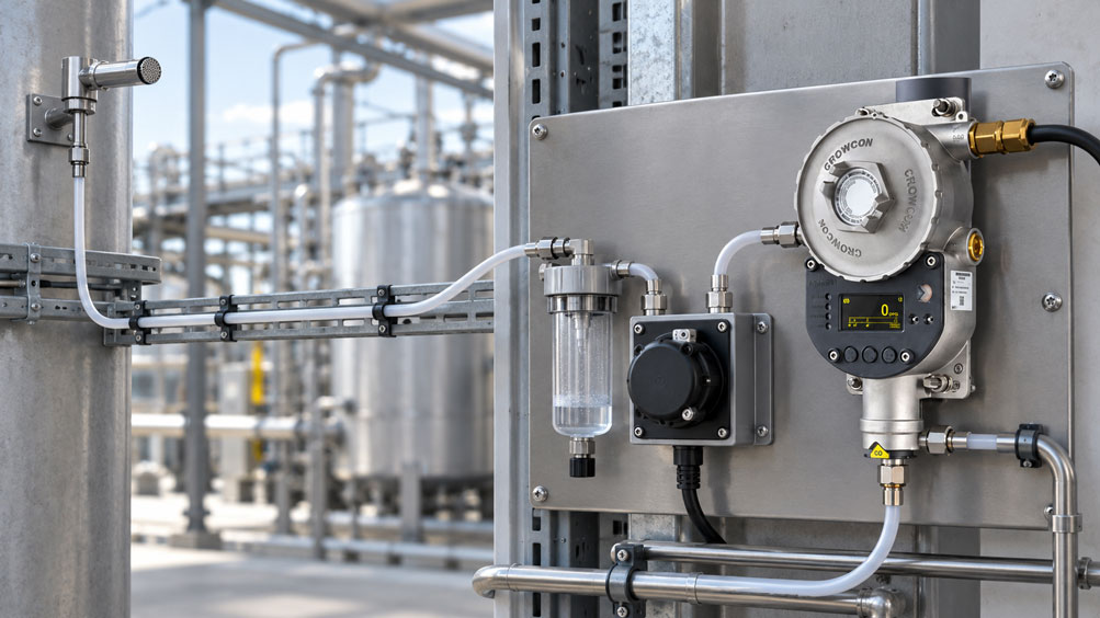
A fixed gas detection system displays the expected gas concentration during routine testing. The alarm relays also operate correctly. Nevertheless, a hazardous gas release at the actual sampling point may not be detected until considerably later. In such cases, the cause may lie not in the sensor or evaluation electronics, but in the sample line between the monitored location and the measuring instrument.
In a fixed gas sampling system with long sample lines, the gas must first be transported over several metres or even greater distances. Transport delays, leaks, condensation, unsuitable tubing materials and changes in flow rate can all affect the measurement. This is particularly critical for reactive or highly water-soluble gases. Even a technically flawless gas sensor can only evaluate the gas mixture that actually reaches it.
Reliable gas detection therefore requires sampling, gas transport, sample conditioning, sensor response and alarm processing to be considered as one interconnected measurement chain. This technical article explains the most important influencing factors, demonstrates how to calculate an idealised gas transport time and describes how condensation, gas losses and delays can be identified during commissioning and routine testing.
Table of Contents
- Define the Monitoring Task and Permissible Response Time
- Understand the Complete Gas Sampling Path
- Correctly Assess Sampling Points and Gas Distribution
- Match Sample Flow Rate to Line Resistance
- Calculation Example: Gas Transport Time in Long Sample Lines
- Distinguish Transport Time, Sensor Response Time and Alarm Delay
- Identify Adsorption, Absorption and Chemical Reactions
- Select Suitable Sample Line and Sealing Materials
- Prevent Condensation and Temperatures Below the Dew Point
- Use Water Separators and Sample Conditioning Correctly
- Evaluate Particle Filters and Hydrophobic Filters
- Consider Line Routing, Temperature and Mechanical Stress
- Check Pumps, Delivery Capacity and Flow Monitoring
- Evaluate Multipoint Gas Sampling and Channel Switching
- Consider Sensor Technology and Gas Compatibility
- Design Safe Sample Gas Exhaust and Explosion Protection
- Correctly Determine Alarm Thresholds and Response Margins
- Test the Complete Gas Sampling System with Test Gas
- Distinguish Sensor Calibration from System Testing
- Diagnose Typical Faults and Their Causes
- Organise Maintenance, Condition Monitoring and Documentation
- Suitable Fixed Gas Detection Technology from ICS Schneider
- Conclusion: The Entire Sampling Chain Determines the Warning Function
- Frequently Asked Questions About Fixed Gas Sampling with Long Sample Lines
1. Define the Monitoring Task and Permissible Response Time
Fixed gas detection systems are used to identify hazardous concentrations of flammable or toxic gases and deviations in oxygen concentration at an early stage. The measurement may serve to warn personnel, monitor technical processes or automatically initiate protective measures.
Before designing a sampling system, it is therefore necessary to establish which target gas is to be monitored, where a hazardous concentration could develop and how quickly the system must respond. Continuous monitoring of a refrigeration machinery room, for example, involves different requirements from monitoring a possible short-duration release of a highly toxic gas.
The permissible response time is not determined solely by the response time of the selected sensor. It depends on how quickly a critical concentration can develop in the relevant hazardous scenario and how much time remains for the intended countermeasure.
For an automatic shutdown, for example, the time required to detect the gas, the processing time within the gas detection system and the response time of the equipment being shut down must all be considered. A long sampling line can consume a significant proportion of the available response margin.
Safety-related design is based on the risk assessment, manufacturer requirements and applicable technical regulations. DGUV Information 213-056 is relevant, among other publications, for toxic gases and oxygen. For gas detection systems used in explosion protection, the corresponding requirements, including those specified in DGUV Information 213-057 and TRGS 722, must be considered.
2. Understand the Complete Gas Sampling Path
In an active gas sampling system, the gas sensor is not necessarily located directly at the monitored position. Instead, a gas sample is transported through a sampling line to the measurement system using a suitable pump or a designated delivery device.
A basic measurement path consists of the following components:
Sampling point → Sample line → Suitable filters and condensate conditioning, where required → Pump/measurement system → Safe sample gas exhaust
The actual sequence of the pump, sensors, filters and conditioning components depends on the device. It must correspond to the configuration approved by the manufacturer. In particular, additional filters or a different pump position can alter the pressure conditions and gas transmission.
Each component performs a specific function. The sampling point collects the gas mixture at the intended location. The sample line transports it. Filters and, where appropriate, water separators protect the system against certain contaminants. The delivery device provides the necessary volumetric flow rate. The sensor converts the composition of the incoming gas into a measurement signal.
A gas detection controller or suitable control system subsequently processes the measured value and initiates alarm or protective functions when the relevant conditions are met.
The most important distinction is that the gas sensor initially measures the concentration at the sensor itself. Whether that concentration still reliably corresponds to the concentration at the sampling point depends on the condition of the entire upstream sampling chain.
3. Correctly Assess Sampling Points and Gas Distribution
The position of the sampling point determines whether a potential gas release can be detected in time. Planning must consider potential leak locations, air movement, ventilation systems, physical obstructions and the properties of the target gas.
Gases are often simply classified as being lighter or heavier than air. This can provide an initial indication, but it is insufficient for every installation. Warm gases may rise, cold gas clouds may initially sink, and strong ventilation currents can significantly alter the direction of dispersion.
The direction of a leak and the presence of enclosures also influence where the highest concentration occurs. In a machinery room, for example, gas may travel along an airflow path before reaching the expected sampling position.
Sampling point locations should therefore be determined from the actual hazardous scenario. Where necessary, flow investigations, suitable tracer tests or other recognised methods may be required to evaluate gas distribution.
Where several sampling points are used, it must not be assumed that a central measuring unit automatically monitors every area simultaneously and without additional delay. Whether sampling takes place in parallel or sequentially must be considered during system design.
4. Match Sample Flow Rate to Line Resistance
The sample flow rate largely determines how quickly gas is transported through the line. For a given line geometry, a higher achievable flow rate results in a shorter idealised exchange time for the internal line volume.
At the same time, flow resistance increases with line length, flow velocity and unfavourable cross-sections. The required pressure differential also depends on filters, fittings, bends and other installed components. A pump may therefore deliver a significantly lower volumetric flow rate through a long line than under almost unrestricted operating conditions.
The nominal flow rate stated in a pump data sheet is consequently not automatically the actual gas flow rate at the sampling point. The decisive factor is the delivery capacity within the complete, operational measurement system.
Dimensioning must consider at least the line length, internal diameter, number of bends, filter flow resistance and pressure conditions throughout the system.
A larger internal line diameter can reduce flow resistance. At the same time, it increases the gas volume inside a line of the same length. If the flow rate is not increased accordingly, the transport time may increase.
There is therefore no universally optimal line diameter independent of the pump characteristic and measurement task. Diameter, length and delivery capacity must be designed together and subsequently verified in the actual installation.
5. Calculation Example: Gas Transport Time in Long Sample Lines
For an initial estimate, the internal volume of a circular sample line can be calculated. The following relationship applies to a line with a constant internal diameter:
V = π · d² · L / 4
Here, V is the internal line volume, d is the internal diameter and L is the line length. If the values are consistently entered in metres, the resulting volume is expressed in cubic metres.
For a constant actual volumetric flow rate Q, an idealised transport time can be calculated:
tideal = V / Q
The result describes the mean volumetric exchange time. It does not automatically represent the actual time until the target gas first arrives, nor the time required for a particular concentration or alarm threshold to be reached at the sensor.
One example considers a sample line with a length of 30 m and an internal diameter of 4 mm. Its geometric internal volume is approximately 0.377 l. At an actual flow rate of 0.5 l/min, the result is:
V ≈ 0.377 l
Q = 0.5 l/min
tideal ≈ 0.754 min ≈ 45 s
The following table shows the influence of line length, internal diameter and flow rate:
| Line Length | Internal Diameter | Actual Volumetric Flow Rate | Line Volume | Ideal Exchange Time |
|---|---|---|---|---|
| 10 m | 4 mm | 0.5 l/min | 0.126 l | approx. 15 s |
| 30 m | 4 mm | 0.5 l/min | 0.377 l | approx. 45 s |
| 30 m | 6 mm | 0.5 l/min | 0.848 l | approx. 102 s |
| 30 m | 4 mm | 1.0 l/min | 0.377 l | approx. 23 s |
These values are calculation examples. They assume a constant volumetric flow rate under comparable pressure and temperature conditions and do not account for additional connected volumes, actual flow profiles, gas interactions or channel switching.
The influence of internal diameter is particularly clear: At the same length and flow rate, a line with an internal diameter of 6 mm has 2.25 times the internal volume of a line with a 4 mm internal diameter. The ideal exchange time increases accordingly.
However, the table must not be interpreted as a general recommendation to use particularly narrow lines. The required flow rate must actually be achievable with the available pump capacity and the total flow resistance.
For safety-related design, the actual gas arrival and alarm response must subsequently be verified experimentally. The volume calculation serves only as an initial design step.
6. Distinguish Transport Time, Sensor Response Time and Alarm Delay
The actual response of a fixed gas detection system results from several successive processes. First, the gas must reach the sampling point. It is then transported through the sample line and passes through the designated conditioning components to the sensor.
The sensor also requires time to respond to the changed gas concentration. Data sheets frequently describe this response using t90. Under the defined test conditions, this value indicates the time required for the sensor signal to reach 90 % of its final change.
Electronic filters, an alarm delay and the response time of downstream equipment may also contribute. In a multipoint system, additional waiting time may arise before the affected sampling point is selected.
The individual times can be considered separately for an initial assessment. However, simply adding the line exchange time to the sensor t90 does not necessarily produce the actual time until the alarm threshold is reached. Gas mixing, the shape of the concentration increase and the selected alarm threshold all influence the result.
Particularly during short gas releases, transport and mixing processes can reduce the concentration peak. The sensor may consequently detect a lower concentration profile or one spread over a longer period than that present at the sampling point.
For safety assessment, the decisive factor is therefore the complete time from the defined gas event at the sampling point until the required warning or protective action takes effect.
7. Identify Adsorption, Absorption and Chemical Reactions
Not every gas is transported unchanged through a sample line. Certain substances can adhere to the internal surfaces of hoses, seals or filters. This process is known as adsorption. Other substances may be taken up into a material or an existing liquid; this process is referred to as absorption.
Chemical reactions with surfaces or contaminants are also possible. As a result, the concentration of the target gas at the sensor may be lower than the concentration present at the sampling point.
Particular attention is required for highly reactive gases such as chlorine, as well as various acidic or alkaline gases. Hydrogen sulphide and certain organic substances can also exhibit significant interactions depending on line material, moisture, concentration and contact time.
The effects do not depend solely on the type of gas. Surface condition, line length, internal diameter, humidity, temperature and previous gas exposure also play a role.
A newly installed clean line may behave differently from one containing ageing products, contamination or existing deposits. The previous exposure history of the line can also influence response and purging behaviour.
Hose materials must therefore not be selected solely on the basis of pressure resistance and temperature range. It is also essential to establish whether the target gas reaches the sensor with sufficiently little alteration during the required transport time.
8. Select Suitable Sample Line and Sealing Materials
Different materials may be suitable for fixed gas sampling applications. Depending on the application and manufacturer approval, these include stainless steel, PTFE, FEP, PFA and certain other plastics.
Selection must be specific to the gas concerned. A material suitable for relatively non-reactive gases must not automatically be used for gases with a strong tendency towards adsorption or chemical reactions.
Fluoropolymers such as PTFE and FEP are frequently considered for applications where low interaction with certain target gases is required. However, they are not completely impermeable to all gases or free from sorption effects under every operating condition.
For ammonia, for example, the documentation for certain MSA gas analysis systems requires specially suitable stainless steel or FEP-lined sample lines. This demonstrates that hose selection can depend on the gas type even within the same product family.
| Component | Possible Influence | Practical Consequence |
|---|---|---|
| PTFE, FEP or PFA line | Favourable surface properties for certain reactive gases; suitability remains gas-dependent | Check the approved configuration, temperature and connection points |
| Stainless steel line | Mechanically robust gas path with suitable chemical resistance under appropriate conditions | Check material grade, surface condition and compatibility with the target gas |
| Other plastic tubing | Depending on the material, possible sorption, permeation or interaction with target gases | No general approval; consult manufacturer data and system test results |
| Elastomer seals | Possible gas absorption, swelling or permeation | Obtain approval of the sealing material for the target gas and operating conditions |
| Filters and membranes | Possible retention of particles, but also interaction with gases | Check gas permeability and effects on response time |
| Fittings and adapters | Additional volume, dead spaces and potential leak points | Limit their number and use suitable gas-tight connections |
A suitable sample line must therefore be assessed as a complete combination of materials. The tubing alone is not sufficient if, for example, an unsuitable sealing material, a filtering connection or a fitting with inadequate leak tightness is used.
For critical gases, testing may be required in which the gas response at the end of the complete sample line is compared with a suitable reference. Both the response characteristics and any possible concentration loss are evaluated.
9. Prevent Condensation and Temperatures Below the Dew Point
A common cause of faults in long sample lines is moisture condensation. If humid gas is drawn in and cooled along the line, its temperature may fall below the dew point of the gas mixture. Water vapour then condenses on the inner wall or accumulates as liquid in lower sections of the line.
The consequences can be considerable. Liquid accumulation reduces the free internal cross-section and increases flow resistance. Depending on the quantity, it can substantially delay gas transport or temporarily interrupt it completely.
For water-soluble target gases, an additional measurement problem arises: Part of the gas may dissolve in the condensate and consequently fail to reach the sensor at its original concentration.
For example, with ammonia and other highly water-soluble substances, the effect of condensate formation on gas transmission must be examined particularly carefully. Removing the liquid may eliminate a mechanical obstruction, but it does not automatically reverse gas losses that have already occurred.
The dew point may also depend on operating conditions when refrigerants, process vapours or other gas mixtures are involved. Where temperatures and humidity vary, the possible extreme conditions throughout the gas path must therefore be assessed.
A typical problem occurs when a warm, humid gas sample is transported through a cold outdoor area. The line may function correctly during warm weather but produce condensate in winter, resulting in altered response characteristics.
A permanently reliable measurement point therefore requires a suitable approach to temperature control and moisture management. The measures must be appropriate for the target gas and measuring principle.
10. Use Water Separators and Sample Conditioning Correctly
Water separators and condensate traps can protect the measurement system against incoming liquids. In certain fixed gas analysis systems, such components are expressly provided for or recommended under appropriate environmental conditions.
However, the separator must be suitable for the gas concerned and the required flow rate. It must not be inserted arbitrarily into the sample line if doing so could change the concentration of the target gas.
This applies particularly to the monitoring of highly water-soluble gases. A water separator can protect the sensor against liquid while the presence of condensate in the line may already have removed some of the target gas.
In addition, every extra component creates flow resistance and potentially adds further gas volume. Draining and maintaining the separator can also be decisive for the availability of the measurement point.
An overfilled condensate container or blocked water separator can result in insufficient gas delivery. The fill level, maintenance requirements and any suitable fault indications should therefore form part of the monitoring concept.
For installations with more demanding requirements, temperature-controlled sampling or another conditioning method suitable for the target gas may be necessary. However, the chosen method must avoid removing or altering the substance being measured.
Sample conditioning is therefore not merely a protective measure for the sensor, but a component of the complete gas detection chain that directly influences measurement performance.
11. Evaluate Particle Filters and Hydrophobic Filters
Dust, aerosols and other contaminants can interfere with gas transport or damage sensors and pumps. Filter elements may therefore be necessary at the sampling point or within the designated sample conditioning system.
A particle filter is intended to retain solid contaminants. Under suitable conditions, a hydrophobic filter can reduce the ingress of liquid water. The actual performance depends on the filter material, pore size, wetting behaviour, pressure conditions and specific design.
Filters must be expressly suitable for the respective gas sampling application. For example, a filter may reliably retain particles but still be unsuitable for a particular reactive target gas if that gas is lost at the filter surface.
As contamination increases, flow resistance also frequently rises. With a pump of limited delivery capacity, this can reduce the actual sample flow rate.
A filter that no longer allows the required quantity of air to pass can therefore significantly delay gas detection. The fact that the sensor continues to display zero or a normal background value does not confirm an adequate gas supply.
Filter condition and flow behaviour must therefore be checked regularly in accordance with the manufacturer’s instructions. Replacement intervals must be determined from the actual exposure conditions and the requirements of the device concerned.
12. Consider Line Routing, Temperature and Mechanical Stress
A long sample line must not only be compatible with the gas but also be installed correctly from a mechanical perspective. Tight bend radii, crushed sections or damaged fittings can reduce the free internal cross-section and impair gas delivery.
Unnecessary line lengths and connecting elements should be avoided. At the same time, the line must not be routed under tensile stress, across sharp edges or through areas where moving machine components could damage it.
The temperature distribution along the line must also be considered. Critical conditions include transitions from warm indoor areas to cold outdoor environments, local cold spots and areas exposed to intense sunlight.
A sample line may develop condensation at low temperatures, while elevated temperatures elsewhere may impair the resistance of the material. Insulated or heated lines may be useful in certain applications. Whether they are necessary and permissible depends on the gas type, dew point and manufacturer approval.
In heated systems, particular attention must be paid to unheated connecting components and short cold sections. Even a continuously heated hose does not prevent condensation if the gas immediately cools in a cold fitting downstream.
Lines should also be clearly identified and remain accessible for maintenance. Where several sample lines run in parallel, clear identification prevents test gas from being inadvertently applied to the wrong sampling point during functional testing.
13. Check Pumps, Delivery Capacity and Flow Monitoring
In an active gas sampling system, the pump performs a safety-relevant function: It must reliably transport the gas from the sampling point to the sensor under actual operating conditions.
Selection must consider the entire pressure-loss path, including the sampling inlet, line, filters, condensate separators, measuring cell and, where applicable, the exhaust line. The permissible operating conditions of the pump must also be observed.
The decisive factor is not merely whether the pump can be heard running. A pump may be operating electrically while a blockage, leak or worn pump component prevents the required sample flow from being achieved.
Suitable flow or pressure monitoring can detect such conditions. However, its location and evaluation logic must be designed so that relevant faults in the actual sampling path are detected.
With several sampling points, monitoring only the total volumetric flow rate may be insufficient. For example, if one individual sampling path is blocked, another line may continue to deliver gas. Whether this fault is detected depends on the design of the distribution and monitoring system.
In a safety-related gas detection function, insufficient or absent sample flow must not go unnoticed or be interpreted as a normal, non-hazardous gas concentration. The system requires a fault response appropriate to the risk assessment.
Fault indications, permissible minimum flow and measures in the event of pump failure must therefore be defined during the engineering stage.
14. Evaluate Multipoint Gas Sampling and Channel Switching
In multipoint systems, several sampling locations are connected to a central gas measuring unit. Depending on the system, sampling may take place simultaneously through separate measurement channels or sequentially through a shared measuring unit.
In sequential systems, a sampling point is connected to the sensor for a specified period. The system then switches to the next point. This can create additional waiting time before a hazardous concentration is detected at a sampling point that is not currently selected.
The actual monitoring time available for each channel must therefore be determined from the switching logic and the required purging or stabilisation times.
When switching between two gas samples with different concentrations, gas from the previous channel may remain in shared line sections or the measuring cell. Without sufficient purging time, this can cause carryover effects or incorrect assignment of the concentration to a particular channel.
The more sampling points a shared measuring unit monitors sequentially, the more carefully the sampling cycle, line volumes and necessary dwell times must be assessed.
The maximum permissible number of channels therefore cannot be determined solely from the number of available connections. It depends significantly on how quickly a hazardous gas event must be detected and at what concentration.
For time-critical protective functions, a dedicated measuring unit for particularly important sampling points or a sensor mounted directly in the hazardous area may be the more suitable solution.
15. Consider Sensor Technology and Gas Compatibility
Fixed gas detection systems can use different sensing technologies. These include electrochemical sensors for numerous toxic gases and oxygen, catalytic sensors for certain flammable gases and infrared sensors for gases suitable for this measuring principle.
Each measuring principle has specific requirements relating to gas type, concentration range, oxygen content, temperature, humidity and possible interfering gases.
A catalytic sensor requires sufficient oxygen for the usual catalytic oxidation of flammable gases. This sensor type may therefore be unsuitable in oxygen-deficient or inerted atmospheres. An infrared sensor may be suitable for certain hydrocarbons, but does not automatically detect all flammable gases. In particular, molecular hydrogen is not detected by conventional infrared hydrocarbon sensors.
Electrochemical sensors may also be sensitive to cross-sensitivities, humidity and other operating conditions. The specific sensor configuration must be suitable for the target gas.
A long sampling line introduces additional influences. A sensor with a good response time when test gas is applied directly may respond considerably more slowly at the end of a long gas path affected by adsorption.
The sensor response time specified by the manufacturer therefore does not necessarily describe the response time of the entire fixed gas sampling system.
Before selection, it must also be established whether the detector concerned is approved for the intended pumped or sampling operation. Not every fixed diffusion-type detector may be connected to an active sampling line without suitable accessories.
16. Design Safe Sample Gas Exhaust and Explosion Protection
After measurement, the sampled gas must be discharged to a suitable location. Particularly with toxic or flammable gases, the exhaust path can be an important part of the safety design.
Sampling must not create a new hazard by transporting a dangerous gas mixture from a monitored area into an occupied room, electrical cabinet or another unsuitable location.
The exhaust line can also create flow resistance and thereby affect the delivery capacity of the complete system. The permissible backpressure and necessary line routing must therefore be considered.
If gas is sampled from a potentially explosive atmosphere, the entire installation, including the sample line, pump, sensor and gas exhaust, must comply with the relevant explosion protection requirements.
Physical separation between a sampling point in a hazardous area and a measuring unit installed in a safe area does not automatically make the gas path safe. A hazardous gas mixture may also be present inside a measuring unit installed outside the hazardous area.
Only suitable components and system concepts approved by the manufacturer for the intended application may be used in such installations.
The design of the gas exhaust and the necessary protective measures must be consistent with the risk assessment and the applicable technical regulations.
17. Correctly Determine Alarm Thresholds and Response Margins
A fixed gas detection system is intended to identify a critical gas concentration in time and initiate a defined warning or protective measure. With active gas sampling, the entire response time from the gas event at the sampling point until the intended action becomes effective is relevant.
The alarm threshold must therefore not be selected independently of the expected development of the gas concentration and the delay caused by gas transport.
Particularly when gas concentrations increase rapidly, a long sample line can consume a considerable proportion of the available response margin. Potential delays caused by filtering, time averaging, alarm delays and the connected plant control system must also be considered.
The concentration actually reaching the sensor is equally important. If some of the target gas is lost through condensation or interaction with the line, a concentration present at the sampling point may remain below the configured alarm threshold at the sensor.
Simply testing the alarm relays with a simulated current or digital value does not detect such faults. It only checks the downstream signal path from the simulation point onwards.
To assess the function, the effective gas transport time, possible concentration losses, sensor response characteristics and alarm or shutdown logic should therefore be considered together.
Appropriate responses must also be provided for sampling faults. A failed pump, blocked line or unavailable measurement point must not go unnoticed and be treated as a safe operating condition.
18. Test the Complete Gas Sampling System with Test Gas
For functional testing of a fixed gas sampling system, the point at which the test gas is applied is crucial. If the gas is introduced directly at the sensor inlet, the sensor and downstream signal path can be assessed. However, the long sample line remains largely outside the scope of this test.
To evaluate the complete sampling chain, a suitable test gas must be applied under defined conditions at the actual sampling point or the designated system test connection. The manufacturer’s instructions and safe testing procedures must be followed.
A practical test procedure may be structured as follows:
- Define the test task: Determine the target gas, test gas concentration, permissible response time and acceptance criteria.
- Identify the measurement point: Document the correct sampling location, line path, sensor used and associated alarm channel.
- Record the initial condition: Check the flow rate, pump status, filter condition and any existing fault indications.
- Prepare a suitable test gas supply: Use an approved test gas source, adapter and gas application procedure in accordance with the manufacturer’s specifications.
- Apply test gas at the sampling point: Introduce the sample into the designated sampling path without impermissible pressurisation or unwanted dilution.
- Document the response profile: Record the time of gas application, increase in the measured value, time at which the alarm threshold is reached and activation of the intended functions.
- Assess concentration transmission: Where required by the test procedure, verify that the signal reaching the sensor meets the defined requirements.
- Check the return to normal operation: Purge the gas path, terminate test mode, restore any bypassed protective functions and document the approved operating condition.
The test gas procedure must be matched to the particular gas, sensor, delivery system and protective function. Applying test gas must not create a hazardous atmosphere or impermissibly alter the pump and measurement conditions.
The measured time to alarm describes the response of the specific measurement chain tested under the documented conditions. It may differ at another flow rate, with a different filter condition, at a different humidity level or with another gas concentration.
For safety-related applications, the test conditions and permissible deviations must be determined from the relevant manufacturer documentation, test concepts and applicable regulations.
19. Distinguish Sensor Calibration from System Testing
Sensor calibration assesses the measuring function of the gas detector under defined conditions. A suitable calibration gas with a known concentration is applied in accordance with the manufacturer’s instructions. Depending on the device, zero point and sensitivity may be checked and adjusted if necessary.
However, this calibration does not automatically confirm that a long sample line is functioning correctly. If calibration gas is applied directly to the sensor, possible losses and delays in the upstream line remain untested.
Conversely, a test gas check through the complete sample line is not automatically a full traceable calibration of the sensor. In particular, it can verify transport, gas transmission, alarm operation and the response of the complete system.
The two tests therefore serve different purposes and can usefully complement each other.
For example, calibration with test gas applied directly to the sensor is suitable for comparing the sensor indication with the calibration gas concentration. An additional functional test at the sampling point shows whether the same gas reaches the sensor in sufficient concentration and within the required time under the intended operating conditions.
If the system test produces unusual results, comparing the two test positions can help identify the cause. If the sensor responds correctly during a direct test but responds much too slowly or indicates a concentration that is too low when test gas is applied at the sampling point, this suggests an influence from the sampling line.
The tests must be documented as separate results. Subsequent sensor adjustment must not be used as a general means of compensating for known gas losses in the line, because the line conditions may change later.
20. Diagnose Typical Faults and Their Causes
Faults in a fixed gas sampling system may become apparent through longer response times, unusually low concentration readings or alarms that fail to activate. However, not every unusual observation has the same cause.
Systematic diagnosis distinguishes between the sampling point, sample line, delivery equipment, sample conditioning, sensor and downstream alarm processing.
| Observation | Possible Cause | Suitable Check |
|---|---|---|
| The sensor responds directly to test gas, but significantly later through the long line | Transport delay, sorption, insufficient flow rate or additional dead volume | Check gas transport time, delivery flow rate and response profile at the sampling point |
| The measured value remains unusually low despite a known gas application | Gas loss through adsorption, condensation or dilution | Investigate gas compatibility throughout the line, moisture and possible leaks |
| Response time deteriorates in cold weather | Condensation, temperature changes or altered delivery conditions | Check the dew point, cold spots and condensate separators |
| The pump runs, but an insufficient gas sample is delivered | Blockage, loaded filters, leakage or pump wear | Check the actual flow rate and pressure conditions throughout the complete measurement path |
| Gas detection responds slowly only at certain sampling points | Different line lengths, channel switching or a blocked individual sampling path | Test each sampling point separately with its assigned measurement channel |
| A test gas signal appears on the wrong measurement channel | Interchanged lines or incorrect channel assignment | Check line identification and system configuration |
| The concentration rises slowly and only decreases slowly after the gas supply is stopped | Sorption and desorption effects or insufficient purging | Check the material, gas type, purging behaviour and dead spaces |
| The gas reading remains normal despite a flow problem | Missing or insufficient monitoring of the sample flow | Check flow monitoring and the intended fault response |
| The gas detection controller operates correctly, but no test gas reaches the sensor | Fault in the upstream sampling or delivery path | Test the complete path from the sampling point to the sensor |
These observations provide diagnostic indications. A specific cause must be verified on the actual system. Several influencing factors may occur simultaneously.
It is particularly important to distinguish between an actual low gas concentration at the sampling point and a technical loss on the way to the sensor. Only when the test conditions are clearly defined can it be determined whether a deviation results from the sample line or from gas distribution within the plant.
21. Organise Maintenance, Condition Monitoring and Documentation
A fixed gas sampling system requires a maintenance concept covering the entire measurement chain. The focus must not be limited to the sensor and evaluation electronics, but must also include sampling points, lines, filters, pumps, condensate separators and gas exhaust lines.
The intended status and fault indications should be evaluated during operation. Examples include pump faults, insufficient sample flow rates and, where applicable, maintenance indications for filters or conditioning components.
Regular inspections must also consider the external and internal condition of accessible sample lines, their identification, possible damage and correct assignment to the measurement channels.
Any modification to a sample line requires reassessment. A different internal diameter, an additional connection, a longer line path or a different filter type can already change the transport time and gas transmission behaviour.
Changes to the target gas, temperature range or humidity conditions can also have an impact. A line that was previously suitable is not automatically suitable for a new measured substance or changed operating conditions.
Traceable documentation therefore includes at least the measurement point designation, gas type, sensor and system configuration, line length, internal diameter, line material, sealing materials and, where applicable, filters and condensate separators.
The intended delivery conditions, alarm thresholds, fault responses and results of functional and calibration tests must also be documented.
When testing with gas applied at the sampling point, the gas type and test gas concentration, time of gas application, measured response profile, alarm activation time and condition of the sampling line should be recorded in particular.
Inspection and maintenance intervals are determined by manufacturer specifications, the risk assessment, relevant regulations and actual environmental and operating conditions. A universally applicable fixed interval for every gas sampling system cannot be derived from line length alone.
22. Suitable Fixed Gas Detection Technology from ICS Schneider
22.1 Crowcon XgardIQ: Fixed Gas Detection with Diagnostic Functions
The Crowcon XgardIQ is a fixed gas detector and transmitter for various flammable and toxic gases as well as oxygen. It features a robust stainless steel housing, a local display and supports different sensing technologies.
Analogue 4 … 20 mA and digital RS-485 signals are available as standard. Depending on the configuration, additional communication and relay functions can be added. Integrated diagnostic and test functions facilitate monitoring of the detector’s condition.
For the present measurement task, the distinction between sensor mounting and active gas sampling is particularly important. Depending on the configuration, the XgardIQ can also be used with a remotely mounted sensor module. However, such an electrically connected remote sensor arrangement is not equivalent to a long gas-carrying sample line.
If active gas sampling is intended, its suitability, accessories and complete configuration must be checked separately against the manufacturer’s approval. General compatibility with an external sampling pump must not be inferred from the detector’s standard specifications.
22.2 Crowcon Xgard Bright: Fixed Detector with Alarm and Communication Interfaces
The Crowcon Xgard Bright is a fixed gas detector with a display, 4 … 20 mA output and additional communication options depending on the configuration. Integrated relays are available for alarm and fault functions.
It is suitable for appropriate fixed gas monitoring applications where the gas type, measuring range and sensing principle match the requirements. The different sensor modules have their own operating and response limits.
When choosing between directly installed sensors and central gas sampling, the locations of possible leaks, accessibility and required response time must be considered. A sensor mounted directly at a suitable monitoring point can avoid the additional transport delay associated with a long sample line.
For the Xgard Bright, too, an external pump or sampling device may only be used if the particular configuration is intended and approved for that purpose.
22.3 Crowcon Gasmaster: Central Evaluation and Alarm Processing
The Crowcon Gasmaster gas detection controller is used for central evaluation of connected gas detectors and other suitable monitoring devices. Depending on the device configuration, it supports multiple inputs as well as alarm, fault and communication functions.
For fixed gas detection systems, the Gasmaster is particularly relevant for processing defined alarm levels and connecting to external warning or control systems.
However, the gas detection controller does not replace the necessary design of the sampling pump and gas-carrying lines. It processes incoming measurement and status signals. A fault in the sampling line must therefore be detected through suitable detector, delivery or monitoring functions and correctly incorporated into the alarm or fault response strategy.
When designing the complete system, it must be established which signals are generated for gas concentration, flow faults, sensor failure and maintenance status, and which actions follow from them.
Further solutions for fixed gas monitoring, gas detection controllers and suitable sensing technologies can be found in the Gas Detectors and Gas Detection Systems category from ICS Schneider. Selection of a complete sampling system must always be based on the specific gases, environmental conditions and required protective functions.
23. Conclusion: The Entire Sampling Chain Determines the Warning Function
Fixed gas sampling with long sample lines can be a suitable solution when gas concentrations must be monitored at remote or difficult-to-access locations. However, its suitability does not depend solely on the gas detector used.
Line length, internal diameter and actual delivery flow rate determine the volumetric transport conditions. Condensation, adsorption, absorption and chemical reactions can additionally change the concentration that reaches the sensor. Pumps, filters and water separators also affect the reliability of gas transport.
For the warning function, the decisive factor is ultimately whether the complete measurement chain detects a hazardous gas event in sufficient time and with adequate reliability. Gas transmission, sensor measurement, alarm processing and fault monitoring must therefore be considered together.
A successful test gas check directly at the sensor does not automatically confirm the operation of a remote sampling point. Likewise, a short calculated transport time does not replace verification of actual gas transmission.
Define the hazard and target gas → Determine sampling point locations → Design the line and delivery capacity → Check material and moisture compatibility → Assess the overall response time → Apply test gas at the sampling point → Verify alarm and fault functions → Document maintenance condition
The most important practical principle is therefore: A fixed gas detection system can only provide a timely alarm if the relevant gas reliably reaches the sensor, with sufficiently little alteration and within the permissible response time, under actual operating conditions.
24. Frequently Asked Questions About Fixed Gas Sampling with Long Sample Lines
24.1 Why Does a Fixed Gas Detection System with a Long Sample Line Respond Slowly?
The gas must first pass through the internal volume of the line and reach the sensor. The sensor response time, possible interactions with the line material and, where applicable, electronic and alarm-related delays must also be considered. Channel switching can introduce additional delays in multipoint systems.
24.2 How Long Can a Sample Line Be in a Fixed Gas Sampling System?
There is no universally applicable maximum length. It depends on pump capacity, internal diameter, flow resistance, target gas, line material and permissible overall response time. The approved limits of the particular system and verification of the required gas transmission are decisive.
24.3 How Can the Transport Time of a Gas Sample Line Be Calculated?
For an initial estimate, the geometric internal line volume is divided by the actual volumetric flow rate achieved. The result describes an idealised exchange time. The actual response and alarm times must also be measured under suitable test conditions.
24.4 Is a Larger Sample Line Automatically Better?
No. A larger internal diameter can reduce flow resistance, but also increases the internal volume at the same line length. Without a correspondingly higher actual flow rate, the exchange time may increase. Design must consider the pump, line and measurement task together.
24.5 Is It Sufficient If the Sampling Pump Can Be Heard Running?
No. A running pump does not confirm that the required gas flow rate is being delivered at the correct sampling point. Blocked filters, leaks or other flow problems can impair gas delivery. Suitable flow and fault monitoring is therefore important.
24.6 Which Tubing Materials Are Suitable for Reactive Gases?
PTFE, FEP, PFA or suitable stainless steel lines are used for certain applications, for example. Actual suitability depends on the target gas, concentration, temperature, humidity and specific material configuration. It must be verified using manufacturer documentation and, where necessary, system testing.
24.7 Why Can Ammonia or Chlorine Be Problematic in Long Sample Lines?
Depending on the conditions, these gases can interact with surfaces or existing moisture. As a result, part of the original concentration may be lost or reach the sensor with a delay. Gas-specific requirements are therefore decisive when selecting line materials and sample conditioning.
24.8 Can Seals Also Affect Gas Sampling?
Yes. Depending on the material and target gas, elastomer seals can absorb, transmit or interact with substances. Fittings and other connecting elements can also create leaks or additional dead volumes. The complete combination of materials must therefore be checked.
24.9 What Happens If Condensation Forms in the Sample Line?
Condensate can reduce the free internal cross-section, obstruct gas flow or block it completely. Water-soluble target gases may also dissolve in the liquid. A water separator may protect downstream components, but does not automatically eliminate concentration losses that have already occurred.
24.10 Is a Water Separator Useful in Every Gas Sampling System?
No. It must be suitable for the gas type, flow rate and measuring principle. An additional component can increase flow resistance and dead volume or affect gas transmission. Its use therefore depends on the approved sampling concept and the actual risk of condensation.
24.11 Can a Filter Distort the Measurement?
Yes. Unsuitable filter materials can retain target gases or change the response time. Flow resistance also frequently increases as filters become contaminated. Filters must therefore be assessed in terms of their protective function, gas compatibility and condition.
24.12 How Can a Leaking Sample Line Be Identified?
Unusual flow rates, abnormal pressure conditions or deviations during defined test gas application may provide indications. Particularly in a suction-based sampling system, ambient air can enter through leaks and dilute the sample. Suitable leak-tightness and functional testing must cover the intended measurement path.
24.13 How Does a Leak Affect Oxygen Measurement?
If gas is sampled from an oxygen-deficient area, ambient air may enter through a leaking line. The oxygen concentration measured at the sensor may then appear higher than the actual concentration at the sampling point. This can be particularly dangerous when monitoring for oxygen deficiency.
24.14 Why Are Multipoint Gas Sampling Systems Sometimes Slower?
With sequential sampling, individual sampling points must be monitored one after another. Additional purging and stabilisation times may be necessary between channels. The longest possible time until a gas event is detected must therefore be assessed based on the complete sampling sequence.
24.15 Does the Sensor Response Time t90 Already Include the Line Transport Time?
As a rule, t90 describes the response characteristics under the test conditions specified in the data sheet. An additional long sample line is not automatically included. The response profile of the entire gas detection system, including the sampling path used, must be determined separately.
24.16 Is Calibration Directly at the Gas Detector Sufficient?
It can verify the measuring function of the detector under the calibration conditions. However, the long sample line is not fully tested in this way. An additional functional test with test gas applied at the sampling point may be required to verify gas transport and actual alarm response.
24.17 Can a Gas Sample Be Transported from a Hazardous Area to a Measuring Instrument in a Safe Area?
Such an arrangement requires a suitably designed and approved solution. The sample line, pump, measuring instrument, gas exhaust and possible hazardous gas mixtures within the system must be considered together. Installing the measuring instrument outside the hazardous area alone does not provide sufficient explosion protection.
24.18 What Information Does ICS Schneider Need for Selection?
The required information includes the target gas or gas mixture, expected concentrations, measuring range, alarm thresholds and required response time. The number and locations of sampling points, planned line lengths and internal diameters, ambient temperatures, gas humidity, possible condensation and particular chemical exposure must also be specified. For the complete gas detection system, requirements relating to pump monitoring, electrical interfaces, alarm and fault functions, explosion protection, calibration and regular functional testing are additionally required.