


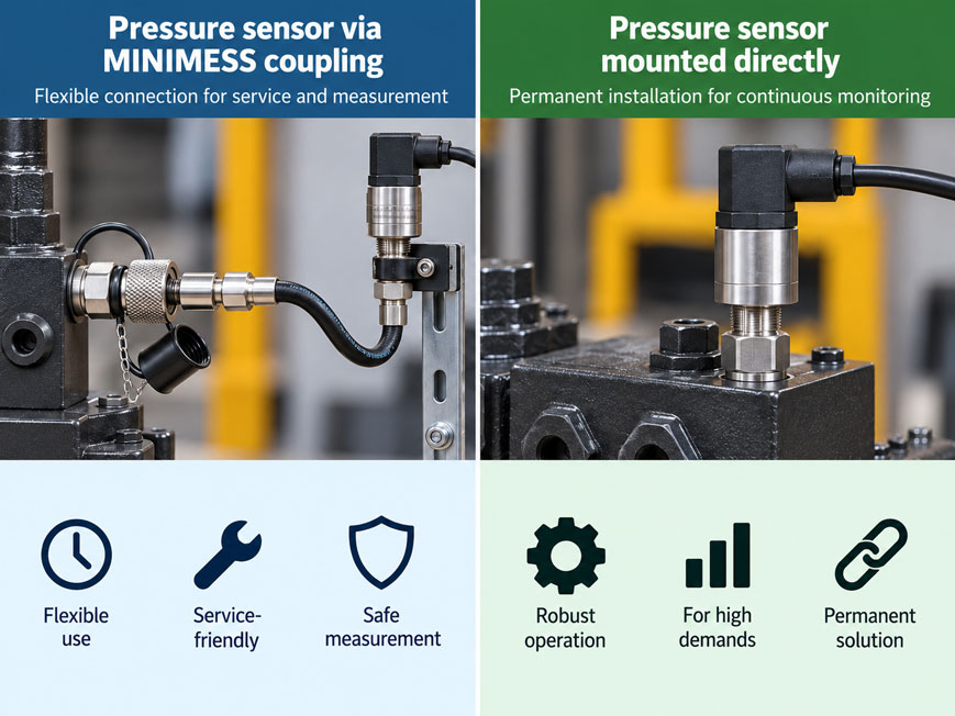
A pressure sensor monitors the operating pressure of a hydraulic press. It is connected to the hydraulic manifold via a MINIMESS test point and a two-meter-long microbore hose. Originally, this connection was established for a temporary service inspection. Because the measurement results were plausible, the sensor remained permanently connected and was integrated into the machine control system.
Several months later, maintenance personnel discover that the pressure sensor detects significantly lower pressure peaks during rapid valve switching operations than a second sensor mounted directly on the hydraulic manifold. However, the steady-state pressure readings agree almost exactly. In addition, the measuring hose must be inspected regularly for abrasion, kinks, and damage.
Is direct sensor mounting fundamentally better? Should a MINIMESS connection only be used for temporary measurements? Or can a permanently connected microbore hose even offer advantages in certain applications?
These questions are particularly relevant for hydraulic power units, mobile machinery, test benches, pump systems, and industrial condition monitoring. Pressure sensors are increasingly used not only during maintenance work but also permanently for process monitoring, recording load cycles, and identifying machine problems at an early stage.
Different options are available for the hydraulic connection. With direct mounting, the sensor is screwed directly into a suitable pressure measuring port or designated connection block using its process connection. The pressure transmission path between the process and sensor diaphragm is therefore comparatively short.
With measurement via MINIMESS, a self-sealing test point is installed in the hydraulic system. A pressure measuring instrument or microbore hose can then be connected using a suitable coupling. This allows the sensor to be mounted at a location separate from the actual process connection.
This physical separation offers significant advantages. For example, the sensor can be positioned outside a hot, heavily vibrating, or difficult-to-access machine area. An existing MINIMESS test point can also be used without having to fundamentally modify the hydraulic line to provide a new sensor connection.
At the same time, additional technical requirements arise. The microbore hose is an independent pressure-bearing component. Its permissible pressure and temperature loading, service life, connecting fittings, and seals must be suitable for the application. The hose must also be permanently protected against kinking, abrasion, tensile loads, and unwanted movement.
Another important aspect is dynamic behavior. With slowly changing or constant pressure, practically the same pressure as at the process connection can develop in a suitable filled measuring line after sufficient stabilization. During rapid pressure changes, however, hose length, internal diameter, hose elasticity, oil viscosity, and trapped gas volumes can alter pressure transmission.
This does not automatically mean that a pressure sensor mounted at the end of a hose is inaccurate. It can measure the pressure actually acting on its sensing diaphragm with high precision. However, during fast processes, this pressure may not be identical in magnitude or timing to the pressure directly at the hydraulic manifold.
There is also an important difference between a permanently installed MINIMESS test point and a permanently connected hose. The closed test point serves as a prepared service connection. If a hose remains connected, the coupling valve is actuated according to its design, and the entire measuring hose is exposed to the corresponding pressure conditions during normal operation.
For a permanent measuring point, not only the pressure sensor but also the test point, hose, fittings, seals, mounting components, and electrical signal transmission must therefore be considered as a complete system.
This technical article compares direct mounting of a pressure sensor with permanent connection via a MINIMESS coupling and microbore hose. It explains the coupling principle, pressure limits, sealing materials, hose routing, vibration behavior, measurement dynamics, leak tightness, and maintenance requirements.
A detailed calculation example shows how hose length and internal diameter influence the enclosed fluid volume, what hydrostatic pressure deviation can result from different installation heights, and why a dynamic pressure pulse may appear differently at the hose end.
Proper installation, diagnostics, safety requirements, calibration, and suitable MINIMESS components and pressure sensors from the ICS product range are also covered.
Table of Contents
- Measurement Task and Choosing Between MINIMESS and Direct Mounting
- Understanding the Different Connection Options
- Operating Principle of a MINIMESS Test Point
- Comparing Direct Mounting and Permanent MINIMESS Connections
- Distinguishing Static and Dynamic Pressure Measurement
- Operating Pressure, Pressure Peaks, and Cyclic Pressure Loading
- Selecting Microbore Hose, Nominal Diameter, and Hose Length
- Practical Example: Calculating Hose Volume, Height Difference, and Measurement Dynamics
- Medium Temperature, Ambient Temperature, and Thermal Isolation
- Sealing Materials, Connection Threads, and Media Compatibility
- Correct Mechanical Installation of Direct-Mounted Sensors and Hose Connections
- Installation Height, Venting, and Trapped Gas Volumes
- Vibrations, Machine Movements, and Mechanical Strain Relief
- Evaluating Rapid Pressure Peaks, Pulsations, and Measurement Bandwidth
- Sealing Points, Hose Aging, and Long-Term Operational Safety
- Pressure Sensors, Measurement Signals, and Condition Monitoring
- Calibration and Verification of the Complete Measurement Chain
- Maintenance Requirements, Retrofitting, and Cost-Effectiveness
- Hydraulic Safety, Protective Measures, and Standards
- Systematic Testing and Commissioning Procedure
- Typical Fault Symptoms and Targeted Diagnostics
- Suitable ICS Products and Connection Solutions
- Conclusion: Selecting the Connection Type According to the Measurement Task and Operating Conditions
- Frequently Asked Questions About MINIMESS and Direct Sensor Mounting
1. Measurement Task and Choosing Between MINIMESS and Direct Mounting
The appropriate connection method for a pressure sensor is not determined solely by the available process thread or maximum operating pressure.
The first decisive factor is which pressure information the system requires and under which conditions the measurement is intended to operate permanently.
1.1 Steady-State Operating Pressure
If a largely constant hydraulic operating pressure needs to be monitored, both suitable direct mounting and a properly designed MINIMESS connection can be appropriate.
With a completely filled and sufficiently stabilized measuring line, the pressure at the sensor is ideally practically equal to the process pressure, provided hydrostatic differences and other influencing factors are considered.
The additional hose does not automatically cause a permanent dynamic pressure loss because no continuous volume flow is required for purely static measurement.
1.2 Slowly Changing Pressure
A microbore line can also transmit measurements adequately when pressure changes slowly.
Whether a relevant delay occurs depends on hose length, internal diameter, viscosity, and the connected sensor volume.
The required response time must therefore match the actual measurement task.
1.3 Rapid Pressure Events
If short pressure peaks, valve switching operations, or high-frequency pulsations are to be recorded, dynamic transmission between the process and sensor becomes significantly more important.
A suitable pressure connection that is as short as possible can then offer advantages.
However, this does not mean that a directly mounted sensor automatically detects every arbitrarily fast pressure peak correctly. Its own bandwidth, the pressure port, and downstream data acquisition must also be suitable.
1.4 Permanent Machine Monitoring
For permanent monitoring, sensors may remain connected to a PLC, data acquisition system, or condition monitoring system for months or years.
In this case, long-term leak tightness, mounting, line construction, and an appropriate maintenance plan must also be considered.
1.5 Service-Friendly Retrofitting
Existing hydraulic systems frequently already have a MINIMESS test point.
A suitable sensor measurement chain can be connected to it in accordance with manufacturer specifications without having to create a new pressure measuring port in the hydraulic manifold.
This can be particularly advantageous for machines with limited installation space or high downtime costs.
1.6 The Key Selection Question
The most important question is therefore not which connection method is fundamentally better, but which solution ensures the required measurement quality throughout the intended service life under safe operating conditions.
2. Understanding the Different Connection Options
In practice, several designs and connection concepts are frequently grouped together under the term pressure sensor connection.
For technical evaluation, they must be considered separately.
2.1 Direct Threaded Mounting
With direct mounting, the pressure sensor is screwed directly into a suitable pressure measuring port or designated connector.
Process pressure reaches the sensing diaphragm through a short internal pressure channel.
The hydraulic connection is comparatively compact.
This can be advantageous for rapid measurements and for minimizing the number of additional pressure-bearing connection elements.
2.2 Sensor Connected via a MINIMESS Microbore Hose
In this configuration, a MINIMESS test point is permanently connected to the hydraulic system.
A suitable measuring hose is connected to the test point and runs to a pressure sensor mounted at a separate location.
The hose transmits pressure between the process connection and the sensor.
Its length can be selected according to the intended application, provided the complete hose assembly is technically suitable.
2.3 Pressure Sensor Connected to the Test Point Using a Short Direct Adapter
Another option is to connect a sensor directly or through a very short connection to a MINIMESS test point using a suitable adapter.
This can result in a smaller additional connection volume than with a longer measuring hose.
However, additional connection elements are still required, and the test point may be subjected to mechanical leverage from the sensor.
Whether this solution is permissible must be checked against the specific coupling, adapter, and sensor design.
2.4 Permanently Installed Service Connection Without a Connected Sensor
A closed MINIMESS test point can remain permanently installed in a system and be used for future service inspections.
As long as no connecting device is coupled, the intended check valve or shut-off element performs the corresponding sealing function.
This is a different operating situation from a measuring hose that remains permanently connected to the system.
2.5 Permanently Connected Sensor with an Additional Service Point
For demanding installations, it may be useful to mount a pressure sensor directly and provide a separate MINIMESS test point for maintenance and reference measurements.
This separates the requirements for permanent measurement from those for service-friendly verification.
However, the additional service connection must also be appropriately designed for pressure and safety.
3. Operating Principle of a MINIMESS Test Point
MINIMESS is a well-known test coupling system for accessing pressurized fluid systems.
Corresponding test points are used particularly in mobile and industrial hydraulics.
3.1 Mechanically Actuated Check Valve
A conventional MINIMESS test point contains a mechanically actuated shut-off or check valve element.
Without a connected mating component, the designated measuring connection is closed.
When a suitable connector is attached, the valve can be opened mechanically.
This establishes pressure access for the connected measuring instrument.
3.2 Connection Under Pressure
Suitable MINIMESS versions are designed for connection under system pressure.
This feature makes them particularly attractive for service and diagnostic work.
However, the permissible coupling and uncoupling conditions depend on the specific series, pressure, medium, and manufacturer instructions.
The basic ability to connect under pressure does not constitute blanket approval for arbitrary measuring instruments, coupling combinations, or operating conditions.
3.3 Sealing Principle
MINIMESS systems use suitable seal and valve constructions depending on their design.
Elastomer seals can provide a low-leakage connection.
For long-term operation, particular attention must be paid to the sealing materials used, temperature, and chemical compatibility with the medium.
3.4 Different Coupling Series
The MINIMESS 1215, 1615, 1620, and 1604 series are among those commonly used in industrial applications.
These series differ in connection geometry and, in some cases, the intended flow cross-section.
The specific series must be identified unambiguously.
A thread that appears similar does not automatically mean that two coupling systems are compatible.
3.5 Permanently Connected Measuring Line
If a measuring hose remains permanently coupled, the entire connection must be suitable for continuous operation.
The connected hose must not be treated as though the closed test point were the only pressure-bearing system boundary.
The hose assembly and all connecting elements form part of the pressurized measurement arrangement.
3.6 Test Point as a Service Component
A permanently installed test point allows pressure measuring instruments, pressure gauges, or pressure sensors to be connected for service work under suitable operating conditions.
Its main advantage is flexible access to the existing hydraulic system.
For a permanent measurement task, it must additionally be determined whether a permanently connected sensor installation is the better overall solution.
4. Comparing Direct Mounting and Permanent MINIMESS Connections
Both connection methods have technical advantages. The suitable configuration depends in particular on the required measurement dynamics, mechanical environment, and maintenance concept.
| Criterion | Direct Mounting | MINIMESS with Microbore Hose |
|---|---|---|
| Hydraulic connection | Short pressure path between process and sensor | Additional test point, hose, and connecting fittings |
| Measurement dynamics | Often preferable for rapid pressure events, provided the pressure port and sensor are suitable | Hose and enclosed volume can alter pressure peaks |
| Static pressure | Direct transmission to the sensor | Generally transmitted accurately after sufficient stabilization; height and filling effects must be considered |
| Mechanical vibrations | Sensor may be directly exposed to vibrations from the hydraulic manifold | Separate, securely mounted sensor can experience reduced vibration loading |
| High process temperatures | Sensor is more directly exposed to the process connection environment | A suitable measuring line can provide physical thermal separation |
| Installation space | Sufficient space required for the sensor housing | Compact test point on the hydraulic manifold; sensor can be positioned elsewhere |
| Sealing points | Often fewer additional connections | Additional coupling, hose, and adapter connections |
| Maintenance | Removal may be more complicated and may require suitable depressurization | Service-friendly connection, but hose and coupling must also be inspected |
| Hose aging | No additional flexible measuring hose required | Hose has its own aging and inspection requirements |
| Retrofitting | A suitable direct process connection must be available | Existing MINIMESS test points can be used |
| Moving machine components | Sensor may move with the mounting block | Flexible connection possible, but movement range and fatigue must be evaluated |
| Leakage risk | Depends on the sensor connection and seal | Additional potential leakage points and hose failure risks |
| Condition monitoring | Particularly interesting for rapid pressure changes and compact permanent measuring points | Interesting for flexible retrofitting and remotely mounted sensors |
| Cost-effectiveness | Fewer additional hydraulic components, but installation may be more complex | Potentially lower modification costs, but additional components and maintenance |
4.1 No Universal Ranking
Direct mounting is not better under all conditions.
With a hot hydraulic manifold subjected to strong vibrations, a remotely mounted sensor connected through a suitable pressure line may be technically preferable.
For a highly dynamic measurement task, however, direct pressure connection may provide better measurement quality.
4.2 The Complete Measurement Chain Is Decisive
A reliable decision must consider not only the mechanical connections but also the pressure sensor, signal processing, and actual process.
A well-designed MINIMESS installation can be more reliable for its intended application than an unsuitable directly mounted sensor.
5. Distinguishing Static and Dynamic Pressure Measurement
When evaluating MINIMESS measuring hoses, a distinction must be made between a steady-state pressure condition and a time-varying pressure signal.
5.1 Static Pressure Equalization
If the measuring line is completely filled with a suitable medium and no significant flow occurs, pressure equilibrium is established after sufficient time.
Taking installation height into account, the pressure measured at the sensor can then correspond to the process pressure.
A long measuring line therefore does not automatically mean that constant pressure is permanently indicated too low.
5.2 Pressure Transmission During Slow Changes
Under slowly changing pressure conditions, the measuring line has sufficient time to follow the process pressure.
Whether a relevant delay occurs depends on the complete hydraulic transfer function.
5.3 Pressure Transmission During Rapid Changes
During a rapid pressure increase, the signal must be transmitted through the test point, hose, connections, and enclosed fluid volume.
These components have finite hydraulic compliance, flow resistance, and fluid inertia.
As a result, the pressure profile at the sensor can differ from the pressure profile at the process connection.
5.4 Hydraulic Resistance
A small internal diameter can create high hydraulic resistance when fluid movement is required.
This particularly influences the transmission of time-varying pressure signals.
5.5 Compressibility and Hose Elasticity
Hydraulic oil has finite compressibility. The hose wall can also expand slightly under pressure.
Both effects contribute to the storage behavior of the measuring line.
Additional gas bubbles can significantly increase compliance.
5.6 Fluid Inertia and Resonance
The fluid column has a mass that must be accelerated during rapid pressure changes.
Depending on the system, pressure waves, resonances, and oscillations can occur.
A measuring hose therefore does not always behave like a simple low-pass filter.
5.7 Consequences for Sensor Selection
The required measurement dynamics must be defined before selecting the sensor and hose assembly.
A measurement chain that is highly accurate under static conditions is not automatically suitable for quantitatively recording short pressure peaks.
6. Operating Pressure, Pressure Peaks, and Cyclic Pressure Loading
The permissible pressure loading of a MINIMESS installation is determined by the specifications of all pressure-bearing components.
6.1 Operating Pressure
The permissible operating pressure must be suitable for the test point, hose, fittings, adapters, and pressure sensor.
The lowest applicable permissible limit within the complete pressure-bearing measurement chain is decisive.
6.2 MINIMESS Pressure Ranges
Operating pressures up to 630 bar are available for suitable standard versions of MINIMESS test points and DN2 microbore hoses.
Other hose variants have lower operating pressure limits.
For example, DN4 versions are offered in different pressure classes.
The pressure specification of a product family must not be interpreted as blanket approval for every combination.
6.3 Pressure Peaks
The maximum process pressure occurring briefly can be significantly higher than normal operating pressure.
These possible loads must be considered when selecting pressure-bearing components.
A high burst pressure rating does not constitute approval to exceed the permissible operating pressure regularly.
6.4 Dynamic Loading
Hydraulic measuring hoses may be subjected to different stresses under pulsating pressure than during predominantly static use.
For certain hose variants, manufacturers therefore distinguish permissible pressure conditions according to application and loading type.
For permanent pulsating applications, the applicable specification of the selected hose assembly must be verified.
6.5 Pressure Rise Rate
The rate of pressure increase can also be relevant during rapid hydraulic operations.
A hose whose maximum operating pressure appears sufficient is not automatically suitable for every possible pressure rise rate.
The corresponding manufacturer limits must be observed.
6.6 Temperature Dependence
The permissible pressure of a hose assembly can depend on temperature and the material combination used.
A sealing material with higher temperature resistance does not automatically increase the permissible temperature or pressure rating of the entire hose system.
6.7 Safety During Continuous Operation
For permanent installation, all maximum expected operating conditions must be considered, including load cycles, pulsations, and temperature changes.
7. Selecting Microbore Hose, Nominal Diameter, and Hose Length
MINIMESS measuring hoses are available in different nominal diameters, materials, and pressure classes.
The actual internal diameter, line length, and mechanical properties are particularly relevant to the measurement task.
7.1 DN2 Microbore Hoses
DN2 measuring hoses typically have an internal diameter of approximately 2 mm.
They provide a compact pressure connection with a small enclosed fluid volume.
Operating pressure classes up to 630 bar are available in suitable versions.
However, the small internal diameter can influence dynamic pressure transmission.
7.2 DN4 Measuring Hoses
DN4 versions have a larger internal diameter, typically approximately 4 mm.
This increases the enclosed fluid volume for the same hose length.
At the same time, hydraulic resistance changes.
Whether DN4 offers better dynamic performance depends on the complete system, including hose elasticity, fluid volume, and sensor connection.
7.3 Hose Length
For rapid pressure measurements, a hydraulic connection that is as short as possible is often advantageous.
However, the required length must provide sufficient allowance for the intended installation, permissible bend radius, and possible machine movements.
A hose that is too short may be subjected to greater mechanical stress than a longer hose that has been routed correctly.
7.4 Internal Diameter
The internal diameter influences fluid volume and hydraulic resistance.
Doubling the internal diameter quadruples the geometric line volume at the same length.
However, the effect on measurement dynamics cannot be determined from volume alone.
7.5 Dead Volume of Fittings
Adapters, couplings, and sensor connections can contain additional small fluid volumes.
These volumes must also be considered in demanding dynamic measurements.
7.6 Protection Against Kinking
The permissible minimum bend radius must be maintained.
Exceeding this bending limit can damage the hose structure and impair operational safety.
7.7 Hose Assembly
The correct hose assembly is specified through hose material, nominal diameter, length, and suitable end fittings.
For a permanently installed measuring point, the finished assembly, including all connections, must be suitable for the operating conditions.
8. Practical Example: Calculating Hose Volume, Height Difference, and Measurement Dynamics
A hydraulic power unit has a normal operating pressure of 120 bar.
A pressure sensor is to be connected either directly to the hydraulic manifold or through a two-meter-long MINIMESS microbore hose.
The remotely mounted sensor is positioned above the hydraulic manifold.
Short-duration pressure peaks are also to be investigated.
The following calculation example considers three distinct influences:
- The enclosed geometric volume of the measuring line.
- The hydrostatic pressure deviation caused by different installation heights.
- Simplified dynamic pressure transmission during a short pressure pulse.
8.1 Initial Data and Assumptions
The following freely selected assumptions apply to this example:
- Normal hydraulic operating pressure: 120 bar.
- Maximum pressure during a hypothetical pulse: 200 bar.
- Pulse duration: 40 ms.
- Measuring hose length: 2.0 m.
- First hose: Internal diameter 2.0 mm.
- Second hose: Internal diameter 4.0 mm.
- Hydraulic oil density: 850 kg/m³.
- Vertical height difference between process connection and sensor: 0.75 m.
- The sensor is located above the process connection.
- The measuring line is completely filled with oil.
- A freely selected time constant of 80 ms is assumed for the simplified dynamic model.
- No additional gas bubbles in the idealized basic case.
All numerical values are model assumptions. They are not guaranteed technical characteristics of any particular MINIMESS hose or pressure sensor.
8.2 Volume of a Cylindrical Measuring Line
The geometric internal volume of a straight cylindrical line is calculated as:
V = π · d² / 4 · L
Where:
- V is the geometric internal volume.
- d is the actual internal diameter.
- L is the length of the line.
8.3 Hose Volume for DN2
For an assumed internal diameter of 2.0 mm:
d = 0.002 m
L = 2.0 m
Therefore:
VDN2 = π · (0.002 m)² / 4 · 2.0 m
VDN2 ≈ 0.000006283 m³
Converted into milliliters:
VDN2 ≈ 6.28 ml
In this simplified geometric model, the two-meter-long DN2 microbore hose contains approximately 6.28 ml of oil.
8.4 Hose Volume for DN4
For an assumed internal diameter of 4.0 mm:
d = 0.004 m
VDN4 = π · (0.004 m)² / 4 · 2.0 m
VDN4 ≈ 0.000025133 m³
Converted:
VDN4 ≈ 25.13 ml
8.5 Comparing the Volumes
The volume ratio is:
VDN4 / VDN2 = 25.13 / 6.28
VDN4 / VDN2 ≈ 4
At the same length, a hose with a 4 mm internal diameter contains approximately four times as much fluid as a hose with a 2 mm internal diameter.
However, this increase in volume does not automatically mean four times the measurement delay.
The actual dynamic behavior also depends on hydraulic resistance, fluid inertia, hose elasticity, and the connected sensor volume.
8.6 Calculating the Hydrostatic Pressure Difference
Pressure in a stationary fluid changes with height.
For a completely filled line:
Δph = ρ · g · Δh
Where:
- ρ is the fluid density.
- g is gravitational acceleration.
- Δh is the vertical height difference.
Using the example values:
ρ = 850 kg/m³
g = 9.81 m/s²
Δh = 0.75 m
the result is:
Δph = 850 · 9.81 · 0.75 Pa
Δph ≈ 6,254 Pa
This corresponds to:
Δph ≈ 0.0625 bar = 62.5 mbar
8.7 Significance of Installation Height
Because the pressure sensor in this example is positioned 0.75 m above the process connection, its static pressure is approximately 0.0625 bar lower than the pressure at the hydraulic manifold when the line is stationary and completely filled with oil.
At a pressure of 120.00 bar at the process connection, this gives:
psensor ≈ 119.9375 bar
For most hydraulic applications with very large pressure measuring ranges, this difference may be comparatively small.
However, it can become relevant with small pressure measuring ranges.
8.8 Significance for a Measuring Range of 0 to 10 bar
If the same height difference occurred at a suitable measuring point with a range of 0 to 10 bar, the hydrostatic difference relative to full scale would be:
ε = 0.0625 bar / 10 bar · 100 %
ε ≈ 0.625 % FS
A height difference that is barely noticeable in high-pressure measurement can therefore represent a significant proportion of the permissible measurement deviation in a small pressure range.
8.9 Dynamic Pressure Peak
Now assume that the process pressure briefly increases from 120 to 200 bar.
The magnitude of the pressure pulse is:
Δp = 200 bar – 120 bar
Δp = 80 bar
The assumed pulse duration is 40 ms.
8.10 Simplified Dynamic Model
For illustration purposes only, a linear first-order transfer function is assumed.
The response to a pressure step is then approximately:
psensor(t) = p0 + Δp · (1 – e-t/τ)
With:
p0 = 120 bar
Δp = 80 bar
t = 0.040 s
τ = 0.080 s
the result is:
psensor(0.040) = 120 + 80 · (1 – e-0.5)
Since e-0.5 is approximately 0.6065:
psensor(0.040) ≈ 120 + 80 · 0.3935
psensor(0.040) ≈ 151.48 bar
Although the process pressure reaches 200 bar during the pulse in the assumed model, the delayed sensor response reaches only approximately 151.48 bar by the end of the 40-ms pulse.
The simplified dynamic difference is:
200 bar – 151.48 bar = 48.52 bar
8.11 Physical Interpretation
This calculation is intended exclusively to illustrate the possible influence of delayed pressure transmission.
The assumed time constant of 80 ms was freely selected and was not determined from the properties of an actual MINIMESS hose.
In a real measuring line, pressure waves, resonances, and other dynamic effects may also occur.
The hydrostatic pressure difference was also intentionally excluded from this separate dynamic model to illustrate the time-dependent effect in isolation.
| Calculated Parameter | Assumption or Formula | Result |
|---|---|---|
| Normal operating pressure | Freely selected process value | 120 bar |
| Hose length | Freely selected example value | 2.0 m |
| DN2 internal diameter | Assumed 2.0 mm | 2.0 mm |
| DN2 internal volume | π · d² / 4 · L | 6.28 ml |
| DN4 internal diameter | Assumed 4.0 mm | 4.0 mm |
| DN4 internal volume | π · d² / 4 · L | 25.13 ml |
| DN4-to-DN2 volume ratio | 25.13 / 6.28 | Approximately 4 : 1 |
| Hydraulic oil density | Freely selected assumption | 850 kg/m³ |
| Vertical height difference | Sensor is positioned higher | 0.75 m |
| Hydrostatic pressure difference | ρ · g · Δh | 0.0625 bar |
| Relative deviation at 0 to 10 bar | 0.0625 / 10 · 100 % | 0.625 % FS |
| Assumed process pressure pulse | 120 to 200 bar | 80 bar pressure change |
| Pulse duration | Freely selected assumption | 40 ms |
| Model time constant | Freely selected assumption, not a product specification | 80 ms |
| Calculated dynamic sensor value | First-order model | 151.48 bar |
| Dynamic difference from the process maximum | 200 – 151.48 bar | 48.52 bar |
8.12 Practical Consequences
The calculation example illustrates three different aspects.
First, the geometric line volume increases with the square of the internal diameter.
Second, installation height can cause a measurable hydrostatic deviation in static pressure measurements.
Third, time-dependent hydraulic transmission can prevent a sensor from detecting a short pressure peak completely or at exactly the same time.
Important: Neither the time constant nor the actual transmission bandwidth can be calculated from hose volume alone. For a quantitative dynamic assessment, the properties of the complete measuring line and sensor must be known or determined experimentally.
9. Medium Temperature, Ambient Temperature, and Thermal Isolation
Temperature influences the selection of the connection method in several ways.
In addition to the permissible sensor temperature, the properties of the measuring line and seals are relevant.
9.1 Temperature Loading with Direct Mounting
With direct mounting, the pressure sensor is located directly at the process connection.
Heat can be transferred through the hydraulic manifold and connection area to the sensor housing.
The permissible medium and ambient temperatures of the sensor must therefore be considered.
9.2 Temperature Loading with Hose Mounting
With a measuring hose installation, the sensor can be mounted at a more favorable location in terms of temperature.
Under suitable conditions, this can reduce thermal loading on the sensor electronics.
However, the hose assembly itself must be suitable for the actual medium and ambient temperatures.
9.3 Hose Material
Standard microbore hoses have limited temperature ranges depending on their construction.
Special hose and material variants are available for higher temperatures.
The specific temperature limit must be obtained from the data sheet for the complete hose assembly.
9.4 Sealing Material
NBR, FKM, EPDM, and other sealing materials have different properties in relation to temperature and media contact.
Using an elastomer with higher temperature resistance does not replace verification of the hose material and fittings.
9.5 Temperature Gradients
A measuring line between a hot process connection and a cooler sensor may experience temperature differences along its length.
These influence oil viscosity, density, and potentially dynamic behavior.
9.6 No Guaranteed Cooling Effect
A longer measuring hose does not automatically guarantee that the sensor will permanently remain within its permissible temperature range.
The actual temperature distribution depends on installation, operating conditions, and heat transfer.
9.7 Overall Thermal Design
For a permanently operating measuring point, the sensor, coupling, hose, seal, connecting fittings, and mounting components must all be matched to the thermal requirements.
10. Sealing Materials, Connection Threads, and Media Compatibility
A safe pressure measuring point requires connections that are mechanically and chemically suitable.
Particularly with MINIMESS systems, connection threads that appear similar must not be confused.
10.1 Coupling Geometry
MINIMESS test points from different series have different connection geometries.
For example, the 1620 series uses an M16×2 coupling interface.
Other series use different interfaces.
The specific series must be stated when ordering.
10.2 Process Thread
The process thread used to install the test point in the hydraulic manifold must be distinguished from the connection geometry for the measuring hose.
Depending on the version, different metric or international male threads may be available.
10.3 G and NPT Threads
Parallel G threads and tapered NPT threads use different sealing principles.
A nominal size that appears geometrically similar does not mean the connections are interchangeable.
Sealing surfaces, threads, and intended sealing elements must be compatible.
10.4 NBR
NBR is frequently used with mineral-oil-based hydraulic media.
Specific suitability depends on medium composition, temperature, and operating conditions.
10.5 FKM
FKM offers advantages under certain elevated temperatures and chemical exposure conditions.
However, it is not equally suitable for every medium.
Media compatibility must be checked for the specific material grade.
10.6 EPDM
EPDM can be suitable for certain water-based media and water-glycol systems.
Suitability for mineral-oil-based media requires particularly careful evaluation.
10.7 PTFE and Special Materials
PTFE and other specialty materials may be intended for certain chemically or thermally demanding applications.
The specific sealing construction and its load capacity must also be considered.
10.8 Changing the Operating Medium
If a hydraulic system is converted to another operating medium, the entire wetted measurement chain must be rechecked for compatibility.
This includes not only the sensor but also the hose inner layer, fittings, and seals.
11. Correct Mechanical Installation of Direct-Mounted Sensors and Hose Connections
Mechanical installation is decisive for leak tightness and service life.
11.1 Direct Mounting
With direct mounting, the pressure sensor must be installed in a process connection intended for that purpose.
Thread, sealing surface, and installation tool must be compatible with the sensor configuration.
The permissible tightening torque must be observed according to manufacturer specifications.
11.2 Mechanical Loading on the Sensor
The sensor housing must not be used as an installation lever unless this is expressly permitted.
Impermissible forces or moments can impair the process connection, sensor construction, or seal.
11.3 Hose Installation
When mounted via MINIMESS, the hose assembly must be routed so that it remains mechanically safe under all intended operating conditions.
This includes the route from the hydraulic manifold to the sensor and the mounting of both ends.
11.4 Minimum Bend Radius
The permissible minimum bend radius must not be exceeded by bending the hose too tightly.
Tight bends should be avoided, particularly immediately behind connecting fittings.
11.5 Avoiding Torsion
A hose assembly must not be twisted impermissibly when tightening the connecting fittings.
Torsion can place long-term stress on the hose structure.
11.6 Hose Mounting
Suitable routing prevents the hose from rubbing against sharp-edged or moving machine components.
Mounting must also accommodate the intended movement and temperature-dependent changes in length.
11.7 Mounting the Sensor Separately
A pressure sensor connected via hose should be secured to a suitable mounting bracket where required by its design.
The hose fitting should not be required to permanently support the entire weight of the sensor housing without appropriate approval.
11.8 Considering the Electrical Connection
Cables must be routed so that tensile forces, vibrations, or excessive bending do not place stress on the sensor.
Electrical connectors and cable glands also require suitable mechanical strain relief.
12. Installation Height, Venting, and Trapped Gas Volumes
When measuring through a hose, the pressure sensor is not necessarily installed at the same height as the process connection.
Trapped gas volumes can also change measurement behavior.
12.1 Hydrostatic Influence
A hydrostatic pressure difference corresponding to the height difference develops in a line completely filled with liquid.
Δp = ρ · g · Δh
For a sensor mounted higher than the process connection, the static pressure at its sensing diaphragm is correspondingly lower.
12.2 Significance for Small Measuring Ranges
With high-pressure sensors, this effect may be relatively small.
With sensors designed for low pressure ranges, however, it can represent a significant proportion of the measuring range.
12.3 Trapped Air
An air bubble inside a hydraulic measuring line is considerably more compressible than the surrounding oil.
It can therefore significantly influence dynamic pressure transmission.
12.4 Gas Accumulation
Poorly routed measuring lines may contain locations where gas accumulates.
The exact effect depends on installation geometry, medium, and pressure conditions.
12.5 Venting
Any necessary venting must be carried out using suitable equipment and an approved procedure.
A pressurized measuring hose must not be loosened in an uncontrolled manner to release trapped air.
12.6 Gaseous Process Media
Gaseous media have different compressibility and safety characteristics from liquid-filled hydraulic lines.
The suitability of the test point, hose, and sensor must be specifically verified for such applications.
12.7 Effect on Calibration
If a sensor is calibrated at a different height from its later operating position, any relevant hydrostatic difference must be considered when evaluating the measurements.
13. Vibrations, Machine Movements, and Mechanical Strain Relief
Hydraulic power units, pumps, and mobile machinery can be exposed to substantial mechanical loading.
13.1 Directly Mounted Sensor
A directly screwed-in sensor is mechanically connected to the hydraulic manifold.
Vibrations and shocks can therefore be transmitted to the sensor housing and electrical connection.
Actual suitability depends on the specified vibration and shock resistance of the sensor.
13.2 Remotely Mounted Sensor
A flexible measuring line allows the sensor to be mounted outside machine areas subject to strong vibrations.
This can reduce mechanical loading on the sensor electronics and electrical connections.
13.3 Mechanical Loading on the Hose Assembly
The advantage of reduced sensor vibration must not come at the expense of poor hose routing.
During repeated movement, the hose assembly may be subjected to bending, torsion, and friction.
13.4 Moving Machine Components
With hydraulic cylinders, mobile machinery, or moving test bench components, the intended movement range must be taken into account.
Hose length, movement allowance, and mounting must be designed accordingly.
13.5 Protection Against Abrasion
Suitable protective devices can protect hose assemblies against mechanical abrasion.
However, their specific design must be suitable for the intended loading.
13.6 Hose Vibrations
The measuring hose itself can also vibrate.
Insufficient mounting can cause additional mechanical loading on the fittings.
13.7 Overall Evaluation
For heavily vibrating machinery, the shortest possible hydraulic connection is not automatically the best mechanical solution.
Selection must consider both the pressure signal and mechanical service life.
14. Evaluating Rapid Pressure Peaks, Pulsations, and Measurement Bandwidth
During rapid hydraulic processes, the measurement chain must be considered as a dynamic system.
14.1 Individual Pressure Peaks
Short pressure peaks can occur, for example, when a valve switches or a hydraulic load is decelerated abruptly.
Their duration can be very short.
14.2 Recurring Pulsations
Pumps or cyclically operating machines can generate recurring pressure fluctuations.
Both amplitude and frequency of the pressure pulsations are relevant.
14.3 Sensor Bandwidth
A pressure sensor must be sufficiently fast for the time-dependent changes of interest.
High static accuracy does not guarantee correspondingly high dynamic bandwidth.
14.4 Hydraulic Transmission
When measuring through a hose, the test point, hose, adapter, and sensor volume influence dynamic pressure transmission.
A fast pressure sensor at the end of an unsuitable measuring line may therefore detect a pressure signal that has already been altered.
14.5 Oscillations and Resonances
During rapid events, the measuring line can exhibit resonance and oscillation effects in addition to damping.
An unusually high recorded pressure peak must therefore also be evaluated critically.
14.6 Data Acquisition Rate
The downstream data acquisition system must be sufficiently fast.
However, a high sampling rate alone does not demonstrate that the complete pressure measurement chain is suitable.
14.7 Anti-Aliasing and Filtering
For digital acquisition, measurement bandwidth, analog filtering, and sampling rate must be coordinated.
Unsuitable filters can modify or suppress rapid pressure events.
14.8 Comparison Measurement
For quantitative evaluation, a time-synchronized comparison between a directly connected sensor and a sensor connected through a hose may be useful.
Identical or appropriately accounted-for measuring points, sensor characteristics, and electrical evaluation conditions are important.
14.9 Distinction from the Specialized Topic
A detailed analysis of the hydraulic transfer function is provided in the supplementary technical article:
15. Sealing Points, Hose Aging, and Long-Term Operational Safety
A permanently connected hose assembly creates additional requirements for leak tightness and maintenance of the measuring point.
15.1 Additional Connection Elements
In addition to the process connection, a hose measurement includes further connections.
These can include the coupling connection, hose fittings, and sensor adapter.
Every connection must be installed correctly and evaluated for leak tightness.
15.2 Permanently Open Test Point
With a permanently coupled measuring line, the valve element of the test point remains actuated according to its design.
The measuring hose is therefore part of the pressurized system.
The safety assessment must not be based solely on the closing function of an uncoupled test point.
15.3 Hose Aging
Hose materials can change as a result of operating time, temperature, media contact, and mechanical loading.
Actual service life depends on the selected hose construction and operating conditions.
15.4 Visual Inspection
Regular inspections should pay particular attention to the following:
- Visible abrasion.
- Kinks or permanent deformation.
- Cracks in the hose cover.
- Corrosion on connecting fittings.
- Damaged bend protection devices.
- Signs of leakage.
- Unusual movements or vibrations.
- Damage to the sensor mounting bracket.
15.5 Replacement and Maintenance
If damage is identified, a hose assembly must not continue operating without an appropriate assessment.
Replacement and inspection intervals must be established according to manufacturer specifications, operating conditions, and applicable regulations.
15.6 Seal Replacement
Seals must be compatible with the coupling and medium.
An arbitrarily selected seal with similar dimensions is not an equivalent substitute for the specified version.
15.7 Maintenance Documentation
For permanently installed hose measuring points, documenting the hose type, assembly, commissioning, and inspections is useful.
This allows the condition of the complete pressure-bearing connection to be traced.
16. Pressure Sensors, Measurement Signals, and Condition Monitoring
The hydraulic connection is only one part of the complete measurement chain.
Electrical signal conditioning also influences the value of the pressure measurement.
16.1 Selecting the Measuring Range
The measuring range must be suitable for normal operating pressure and the maximum possible process pressure conditions.
A sensor with an insufficient permissible pressure rating can be damaged by pressure peaks.
An unnecessarily large measuring range can adversely affect absolute resolution or achievable measurement uncertainty.
16.2 Gauge and Absolute Pressure Measurement
Before selecting a sensor, it must be determined whether gauge pressure or absolute pressure is required.
The pressure type influences comparability with other measuring instruments and subsequent evaluation.
16.3 Output Signal
Typical industrial pressure sensors offer 4-to-20-mA or voltage outputs, for example.
The output signal must be compatible with the existing PLC or data acquisition system.
16.4 Dynamic Pressure Sensors
For rapid pressure events, bandwidth, response characteristics, and suitable output electronics must also be verified.
A sensor may be suitable for static process monitoring without automatically meeting the requirements for dynamic pressure peak measurement.
16.5 Data Acquisition
During permanent condition monitoring, measurements can be recorded continuously.
The required sampling rate depends on whether slow trends or rapid pressure events are being investigated.
16.6 Limit Values
A pressure sensor can provide information for alarms or other process functions.
However, a conventional measurement chain is not automatically suitable for a safety-related protective function.
16.7 Condition Monitoring
In condition monitoring, long-term changes in pressure profiles can indicate wear, changed pump conditions, or unsuitable switching operations.
Interpretation requires the measurement signal to be transmitted reliably and reproducibly.
16.8 Trend Measurement and Pressure Peak Analysis
A measurement chain can be well suited to long-term trend monitoring while failing to reproduce very short pressure events completely.
The requirements for trend monitoring and dynamic analysis should therefore be defined separately.
17. Calibration and Verification of the Complete Measurement Chain
When evaluating measurement quality, the pressure sensor itself must be distinguished from its complete installation.
17.1 Pressure Sensor Calibration
Calibration of the pressure sensor determines its deviations from a suitable pressure reference under defined conditions.
It initially describes the sensor characteristics under the selected test conditions.
17.2 Measurement Through the Complete Line
Additional influences can occur in an installation with a MINIMESS test point and microbore hose.
These include hydrostatic differences, trapped gas volumes, and dynamic transmission effects.
17.3 Static Testing
For static testing, defined pressure points can be established and compared with a suitable reference after sufficient stabilization.
The actual installation heights and pressure conditions must be considered.
17.4 Dynamic Testing
Dynamic testing examines behavior during time-varying pressure signals.
This requires a suitable test setup and a sufficiently fast reference measurement chain.
Static calibration alone does not demonstrate correct transmission of very short pressure pulses.
17.5 Measurement Uncertainty
The measurement uncertainty of the complete measurement chain can include contributions from the sensor, pressure reference, temperature, installation height, and signal processing.
Dynamic applications introduce additional time-dependent influences.
17.6 Before-and-After Comparison
When changing from hose measurement to direct mounting, a comparison measurement may be useful.
The measured values must be recorded under suitable and traceable process conditions.
17.7 Documentation
The test report should clearly identify the sensor, measuring range, test point, hose, line length, installation height, test conditions, and reference.
This ensures that the conditions under which the results were obtained remain traceable.
18. Maintenance Requirements, Retrofitting, and Cost-Effectiveness
In addition to measurement quality, selecting the connection method also influences installation and maintenance requirements.
18.1 Advantages of an Existing MINIMESS Measuring Point
If a suitable test point is already available, an additional measurement can often be implemented with comparatively little modification work.
This is particularly attractive for existing machinery and hydraulic power units.
18.2 Additional Components
However, permanent hose measurement requires additional pressure-bearing components.
These include the hose, fittings, adapters, and potentially mechanical sensor mounting brackets.
18.3 Installing a Direct Measuring Point
Direct mounting requires a suitable process connection.
If one is not available, modification of the hydraulic manifold or a suitable additional connecting component may be necessary.
Such work must follow an approved procedure.
18.4 Replacing the Sensor
A sensor connected via MINIMESS can be positioned for convenient servicing in a suitable configuration.
However, replacement must take account of safe depressurization or the approved disconnection procedure for the specific coupling.
18.5 Long-Term Maintenance Requirements
An additional hose assembly requires its own inspections and potentially replacement.
These specific hose maintenance tasks are eliminated with a suitable direct mounting arrangement.
18.6 Downtime
An existing MINIMESS service point can simplify diagnostics and certain maintenance operations.
Whether this actually reduces downtime depends on the plant design and approved working procedure.
18.7 Life-Cycle Costs
An economic evaluation should consider not only purchase costs but also installation, leak testing, maintenance, hose replacement, and possible plant downtime.
18.8 Decision Based on Operating Duration
A MINIMESS connection can be particularly economical for short-term service work and flexible diagnostic tasks.
For a measuring point operated permanently over many years, suitable direct mounting may offer advantages.
However, no universally applicable economic ranking can be established without knowing the specific installation.
19. Hydraulic Safety, Protective Measures, and Standards
A measuring line that remains permanently pressurized must be safe to operate under the intended conditions.
The safety assessment must not be limited to the nominal pressure of the pressure sensor.
19.1 ISO 4413
ISO 4413 describes general rules and safety requirements for hydraulic systems and their components.
Requirements relating to design, operation, maintenance, and hazard prevention are relevant when designing hydraulic measuring points.
19.2 Pressure-Bearing Components
The test point, hose, fittings, and sensor must be suitable for the possible pressure conditions.
The permissible loading of the complete assembly is determined by the respective component limits.
19.3 High-Pressure Injection Injuries
Hydraulic fluid escaping under high pressure can cause severe injuries.
In particular, a very fine jet of fluid can penetrate the skin.
Suspected leaks must therefore never be located by feeling for them with a hand.
19.4 Hose Failure
Failure of a pressurized hose assembly can result in sudden fluid discharge and uncontrolled movement.
The risk assessment determines whether additional shielding, restraint systems, or other protective measures are required.
19.5 Hot Hydraulic Fluids
Elevated medium temperatures can create additional burn hazards.
Actual operating conditions must be considered during maintenance and sensor replacement.
19.6 Connecting Under Pressure
The ability to connect suitable MINIMESS couplings under pressure is a design characteristic of certain versions.
It does not replace verification of the specific product approval or compliance with the required protective measures.
19.7 Depressurized Maintenance Condition
For work requiring depressurization, this condition must be established and verified according to the approved plant procedure.
Stored hydraulic energy in accumulators or isolated line sections must also be considered.
19.8 Hazardous Areas
For applications in hazardous areas, the complete electrical measurement arrangement must be suitable for the environment.
A mechanical MINIMESS test point does not replace the required explosion protection assessment of the sensor and its electrical components.
19.9 Applicable Documentation
The relevant documentation for the specific configuration includes manufacturer data sheets, hose assembly specifications, installation manuals, machine documentation, and the results of the risk assessment.
20. Systematic Testing and Commissioning Procedure
A documented testing and commissioning procedure is recommended for permanently installed pressure measuring points.
The following steps apply both to direct mounting and to permanent connection via a MINIMESS measuring hose.
- Define the measurement task: Specify whether the objective is steady-state operating pressure, slow pressure changes, or rapid pressure peaks.
- Record process conditions: Document maximum pressure, pressure pulsations, medium, and temperature.
- Determine required measurement dynamics: Define the necessary bandwidth and time resolution.
- Inspect the installation location: Evaluate available space, temperature, vibrations, and accessibility.
- Select the connection method: Choose direct mounting, a MINIMESS hose, or another suitable connection.
- Specify the pressure sensor: Select measuring range, pressure type, overload capability, and output signal.
- Check the process connection: Compare the thread and sealing principle with the existing connections.
- Identify the MINIMESS series: For hose mounting, clearly identify the existing coupling geometry.
- Select the hose assembly: Define nominal diameter, length, operating pressure, temperature, and end fittings.
- Verify dynamic load capability: Compare pressure rise rate and pressure pulsations with hose specifications.
- Check material compatibility: Match the hose inner layer, fittings, and seals to the medium.
- Plan hose routing: Consider bend radius, movements, abrasion protection, and strain relief.
- Specify the sensor mounting bracket: Ensure suitable mounting and mechanical strain relief.
- Document installation height: Consider relevant hydrostatic pressure differences.
- Check electrical connections: Verify supply, output signal, connectors, and wiring.
- Perform hydraulic installation: Follow manufacturer specifications and the approved working procedure exclusively.
- Perform a leak test: Test the complete measurement arrangement using a suitable procedure.
- Evaluate the filling condition of the measuring line: Remove trapped gas volumes if necessary according to an approved procedure.
- Perform a static comparison measurement: Compare the measured value with a suitable reference.
- Check dynamic behavior: Where required, investigate pressure transmission and sensor bandwidth.
- Check signal processing: Verify scaling, filters, sampling rate, and limit values.
- Evaluate safety measures: Consider the risk assessment, line protection, and required pressure limitation.
- Establish a maintenance concept: Define inspection and replacement intervals for the components.
- Complete documentation: Record the sensor, coupling, hose, mounting location, test conditions, and results.
If the sensor is replaced later or the hose routing is changed, the relevant tests must be repeated.
The procedure described does not replace binding manufacturer specifications or any necessary safety approval of the installation.
21. Typical Fault Symptoms and Targeted Diagnostics
When unusual measurements occur, the first step should be to determine whether the cause lies in the pressure sensor, hydraulic connection, or actual process.
The following table shows typical fault symptoms and suitable diagnostic approaches.
| Fault Symptom | Possible Cause | Suitable Diagnostic Action |
|---|---|---|
| Pressure measured through the hose responds with a delay | Hydraulic resistance, compliance, or trapped gas volume | Check hose length, nominal diameter, filling condition, and dynamic transmission |
| Short pressure peaks are indicated lower via MINIMESS | Attenuation of fast pressure components by the measuring line | Compare with a suitable direct reference measurement and time synchronization |
| Pressure peaks appear unusually high | Possible resonance or oscillation of the measuring line | Investigate the dynamic measurement chain and signal processing |
| Static pressure does not agree with the direct reference value | Height difference, sensor deviation, gas volume, or another influence | Check installation height, pressure reference, stabilization, and measuring line |
| Measured value drifts after a pressure change | Thermal settling, leakage, or changing fluid conditions | Check temperature, leak tightness, and time-dependent behavior |
| Hose shows visible abrasion | Unsuitable routing or mechanical movement | Inspect the measuring point using a safe procedure and evaluate hose condition |
| Leakage at coupling or adapter | Damaged seal, unsuitable connection combination, or incorrect installation | Inspect the connection after depressurization according to manufacturer specifications |
| Hose kinks immediately behind the fitting | Unsuitable length or failure to maintain the minimum bend radius | Redesign hose assembly and routing |
| Directly mounted sensor fails under strong vibrations | Insufficient mechanical resistance or electrical contact problems | Check sensor mounting, vibration loading, and connecting cable |
| Sensor at hose end becomes very hot | Insufficient thermal separation or unsuitable installation location | Check temperature conditions and component limits |
| Different pressure readings occur after sensor replacement | Different span, zero point, installation height, or changed connection | Compare sensor parameters and complete measurement chain |
| Sensor provides stable readings but implausible pressure peaks | Unsuitable measurement bandwidth or filtering | Evaluate sensor bandwidth, line, and data acquisition rate |
| Pressure sensor indicates a constant value despite the plant operating | Blocked measuring connection, isolated fluid section, or electrical interference | Safely check the measuring point, hydraulic continuity, and electrical signal |
The listed causes are possible diagnostic approaches and do not constitute definitive fault identification.
Particularly in high-pressure applications, testing must not involve uncontrolled loosening of pressurized connections.
22. Suitable ICS Products and Connection Solutions
ICS Schneider Messtechnik offers different MINIMESS test points, microbore hoses, pressure sensors, and portable measuring systems for hydraulic service and permanent measurement applications.
The appropriate solution depends on operating pressure, temperature, media compatibility, connection geometry, and measurement dynamics requirements.
22.1 MINIMESS 1620 – Compact Pressure Measurement and Service Connection
The MINIMESS 1620 is a mechanically actuated test point for pressure access to hydraulic and other suitable fluid systems.
It is used in particular for pressure monitoring, diagnostics, filling, venting, and sampling.
Documented features include:
- MINIMESS M16×2 coupling interface.
- Mechanically actuated check valve.
- Suitable versions for coupling under system pressure.
- Operating pressures up to 630 bar for appropriately specified variants.
- Different male threads for the process connection.
- Various material configurations.
- Sealing options including NBR, FKM, and EPDM.
- Connection to suitable MINIMESS measuring hoses and adapters.
The MINIMESS 1620 is particularly interesting when an existing hydraulic installation requires a service-friendly measuring point.
Permanent sensor connection through a suitable hose assembly can also be evaluated for the specific application.
For this purpose, coupling, hose assembly, and sensor must be assessed together in terms of pressure, temperature, continuous loading, and safety.
Further Information: MINIMESS 1620 at ICS Schneider Messtechnik
22.2 MINIMESS 1215 – Compact Test Point for Restricted Installation Spaces
The MINIMESS 1215 is a compact test point series for suitable measurement and service applications.
Its compact design is particularly useful where installation space is limited.
Documented features include:
- Mechanically actuated test point function.
- Compact connection geometry.
- Suitable versions for measurement and service work under specified operating conditions.
- Various process connection options.
- Versions made from suitable steel and stainless steel materials.
- Different elastomer seals.
- Application for pressure monitoring, venting, and other service functions.
The specific connection geometry of the 1215 series must be observed.
It is not automatically interchangeable with the connection geometry of a MINIMESS 1620 coupling.
A compatible and suitable connection is therefore required for a permanent hose measuring point.
Further Information: MINIMESS 1215 at ICS Schneider Messtechnik
22.3 MINIMESS Hoses – Microbore Lines for Pressure Measurement and Service
The MINIMESS hose range includes different microbore hoses for pressure measurement, service, and diagnostic applications.
Different nominal diameters, pressure ranges, hose materials, and connecting fittings are available depending on the configuration.
Documented features include:
- DN2 and DN4 versions.
- DN2 hoses in different pressure classes up to 630 bar.
- DN4 hoses in various pressure classes, including 315 and 450 bar.
- Different hose materials.
- Customer-specific hose lengths.
- Various suitable connecting fittings.
- Suitable solutions for hydraulic measurements and service work.
- Information on media compatibility, hose routing, and storage.
When selecting a permanent measuring line, particular attention must be paid to permissible dynamic loading, temperature, chemical resistance, and mechanical routing.
The permissible pressure loading of the complete hose assembly is determined by the lowest-rated applicable component.
A larger internal diameter or longer hose does not automatically provide better measurement dynamics.
Further Information: MINIMESS Hoses at ICS Schneider Messtechnik
22.4 MINIMESS 1615 and 1604 – Additional Connection Options
In addition to the frequently used 1215 and 1620 series, further MINIMESS connection options are available.
The 1615 series uses a different coupling geometry from the 1620 series.
The 1604 series is particularly interesting for suitable applications with a larger flow cross-section or corresponding service functions.
The exact selection depends on:
- Existing coupling series.
- Required process connection.
- Desired nominal hose diameter.
- Permissible operating pressure.
- Medium and temperature.
- Availability of suitable connecting fittings.
Clear identification of the coupling series is particularly important for existing installations.
Different thread and valve constructions must not be considered interchangeable solely because their external dimensions appear similar.
Further Information: MINIMESS 1615 Series
Further Information: MINIMESS 1604 Series
22.5 Druck UNIK5000 – Configurable Industrial Pressure Sensor
The Druck UNIK5000 is a modular, configurable pressure sensor for industrial and demanding measurement applications.
Its various process connections, measuring ranges, and electrical output options make it suitable for different installation conditions.
Documented features include:
- Pressure measuring ranges from 70 mbar to 700 bar across the product family.
- High measurement accuracy down to ±0.04 % FS according to the specified BSL assessment.
- Stainless steel construction.
- Various electrical output signals.
- Different process connections.
- Configuration-dependent overpressure resistance.
- Frequency response up to 3.5 kHz in suitable configurations.
- Different temperature and approval options.
The UNIK5000 may be suitable, for example, where compact direct mounting with high measurement dynamics is required.
Depending on the configuration, it can also form part of a suitable measurement arrangement with a MINIMESS connection.
However, the actual usable dynamic bandwidth is determined by the sensor variant, pressure connection, measuring line, and downstream acquisition system.
Particularly with measuring hose connections, the sensor’s frequency response must not automatically be interpreted as the bandwidth of the complete hydraulic measurement chain.
Further Information: Druck UNIK5000 at ICS Schneider Messtechnik
22.6 WIKA S-20 – Pressure Transmitter for Industrial Applications
The WIKA S-20 is an industrial pressure transmitter for demanding pressure measurement tasks.
It is available in different measuring range and connection configurations.
Documented features include:
- Measuring ranges from 0 to 0.4 bar up to 0 to 1,600 bar.
- Nonlinearity down to 0.125 % of span in appropriately specified configurations.
- Various electrical output signals.
- Different industrial process connections.
- Robust construction for demanding environments.
- Different electrical connection options.
The WIKA S-20 is suitable for consideration for a direct pressure measuring point or an application-specific measuring line.
The specific version must be selected according to medium, pressure, temperature, mechanical loading, and required measurement dynamics.
An additional MINIMESS adapter or hose is not automatically included in the standard configuration.
Further Information: WIKA S-20 at ICS Schneider Messtechnik
22.7 Hydrotechnik MultiSystem 5070 – Portable and Dynamic Data Acquisition
The Hydrotechnik MultiSystem 5070 is a portable multichannel measuring instrument for hydraulic measurement and diagnostic applications.
It can record various hydraulic and electrical measured quantities over time.
Documented features include:
- Five-inch color display.
- Multichannel data acquisition.
- Up to 42 measurement or calculation channels in suitable configurations.
- Sampling rate up to 10 kHz.
- Storage of extensive measurement series.
- Support for various analog industrial signals.
- Digital communication interfaces.
- Suitable for hydraulic diagnostics and service applications.
The MultiSystem 5070 can be used, among other things, to investigate time-dependent pressure events and compare different pressure measuring points.
For dynamic pressure measurement, the sensor used must be sufficiently fast.
If the sensor is connected via a MINIMESS microbore hose, its hydraulic transfer function must also be considered.
A sampling rate of up to 10 kHz does not automatically mean that the complete measurement chain reproduces pressure peaks unchanged with a corresponding bandwidth.
Further Information: Hydrotechnik MultiSystem 5070 at ICS Schneider Messtechnik
22.8 Technical Selection of a Complete Measuring Point
The following information should be available when selecting a pressure measuring point suitable for permanent operation:
- Normal operating pressure.
- Maximum possible process pressure, including pressure peaks.
- Frequency and dynamics of pressure changes.
- Measuring medium and relevant constituents.
- Minimum and maximum medium temperature.
- Ambient temperature.
- Available process connection.
- Existing MINIMESS series.
- Desired sensor location.
- Required hose length.
- Nominal hose diameter and pressure class.
- Suitable fittings and sealing materials.
- Mechanical vibrations and movements.
- Required accuracy and measurement bandwidth.
- Required output signal.
- Existing PLC or data acquisition system.
- Required safety and protective measures.
- Maintenance and inspection requirements.
- Any required calibration and documentation.
Based on this information, it can be determined whether direct mounting, a short adapter connection, or a permanent MINIMESS measuring hose solution is best suited to the measurement task.
MINIMESS Couplings and Hose Technology at ICS Schneider Messtechnik
23. Conclusion: Selecting the Connection Type According to the Measurement Task and Operating Conditions
The question of whether a pressure sensor should be permanently connected via MINIMESS or mounted directly on the hydraulic manifold cannot be answered with a single recommendation for every application.
Both connection methods offer technical advantages and must be evaluated according to the actual measurement task.
Direct mounting generally provides a compact pressure connection with a short hydraulic measurement path.
This can reduce additional influences caused by hose volume, hose elasticity, and long connecting lines.
It can be particularly advantageous for rapid pressure events and the investigation of short pressure peaks.
However, the pressure sensor itself must have sufficient measurement bandwidth, and the process pressure port must be hydraulically suitable.
A directly mounted sensor is also exposed directly to the mechanical and thermal conditions at the process connection.
Strong vibrations, high temperatures, or unfavorable installation conditions can therefore impose additional requirements on the sensor design and mounting.
By contrast, permanent MINIMESS connection through a microbore hose allows the sensor to be physically separated from the actual hydraulic connection.
This can simplify maintenance, allow installation at a more favorable temperature location, and reduce mechanical loading.
Particularly in existing installations with MINIMESS test points already available, installation work can be reduced.
However, these advantages must be weighed against the additional requirements of the pressure-bearing measuring line.
With a permanently connected line, the test point, hose, connecting fittings, seals, and sensor form one pressure measurement assembly.
The permissible operating pressure limit is determined by the relevant component specifications.
Pressure peaks, temperature, cyclic pressure loading, hose routing, and mechanical stresses must all be considered.
In particular, the maximum operating pressures stated for a hose variant must not be applied to every permanent dynamic application without verification.
For static pressure measurement, a suitable, completely filled microbore hose can provide useful results even over longer lengths.
After sufficient stabilization, pressure equilibrium is generally established, although hydrostatic effects caused by height differences must be considered.
The situation can change significantly during rapid pressure variations.
The hose has hydraulic resistance, a certain compliance, and fluid inertia. Together with sensor volume and possible air bubbles, these create a specific dynamic transfer function.
As a result, very short pressure peaks may be attenuated, shifted in time, or altered by oscillations under certain conditions.
The calculation example also shows that doubling the hose internal diameter at the same length quadruples the enclosed fluid volume.
However, this volume change alone does not allow a universally applicable conclusion about the actual measurement bandwidth.
For reliable dynamic measurement, the sensor and hydraulic connection must therefore be evaluated together.
From an economic perspective, MINIMESS can be particularly attractive for retrofitting, service, and flexibly accessible measuring points.
However, long-term permanently installed measuring points must also account for the additional effort associated with hose inspections, sealing points, and possible replacement.
In certain applications, combining a directly mounted pressure sensor with an additional MINIMESS service connection can meet the requirements for measurement quality and maintenance convenience particularly well.
The key conclusion is: A permanently connected MINIMESS microbore hose is not fundamentally an inferior pressure connection, but it introduces an additional hydraulic and mechanical system. For slowly changing pressure measurements, it can be a practical and reliable solution. For rapid pressure peaks and applications with demanding measurement dynamics, however, a suitable pressure connection that is as short as possible is often advantageous. The correct decision must always consider measurement quality, pressure resistance, temperature, vibrations, leak tightness, and the safety of the complete measuring point.
24. Frequently Asked Questions About MINIMESS and Direct Sensor Mounting
24.1 Can a Pressure Sensor Remain Permanently Connected via MINIMESS?
Yes. With suitable design, a pressure sensor can be operated permanently through a MINIMESS test point and a compatible microbore hose. The coupling, hose, fittings, and sensor must be suitable for the actual pressure, temperature, and media conditions. Mechanical hose routing and long-term inspection requirements must also be considered.
24.2 Is Direct Pressure Sensor Mounting Fundamentally Better?
No. Direct mounting can offer advantages for rapid pressure events because the hydraulic connection path is comparatively short. At high temperatures, under strong vibrations, or where accessibility is poor, a remotely mounted sensor connected through a suitable measuring line may be preferable. Correct selection depends on the complete measurement task.
24.3 What Is the Difference Between a MINIMESS Test Point and a Permanently Connected Measuring Hose?
A MINIMESS test point is a permanently installable service connection with a designated shut-off or check valve element. When no mating connector is attached, the measuring connection is closed according to its design. With a permanently coupled measuring hose, however, the entire line up to the pressure sensor forms part of the pressure-bearing measurement chain.
24.4 Does a MINIMESS Microbore Hose Affect Pressure Measurement?
Yes, particularly during rapid pressure changes. Hose length, internal diameter, hose elasticity, oil viscosity, and trapped gas volumes can change dynamic pressure transmission. With constant pressure, however, practically the same pressure can develop at the sensor after sufficient stabilization, provided height differences and other influences are considered.
24.5 Why Does a Sensor Connected via MINIMESS Sometimes Indicate Lower Pressure Peaks?
One possible cause is dynamic attenuation by the hydraulic measuring line. The pressure pulse can be delayed or altered in amplitude by the properties of the test point, hose, and connected sensor volume. A suitable time-resolved comparison measurement is required for verification.
24.6 Can a MINIMESS Hose Assembly Also Indicate Excessively High Pressure Peaks?
Under certain dynamic conditions, pressure waves, resonances, or oscillations can occur. As a result, the pressure profile at the sensor can differ from the original process pressure. An unusually high recorded pressure peak should therefore also be evaluated based on the complete measurement chain.
24.7 Which MINIMESS Series Is Suitable for a Pressure Sensor?
The 1620 series with an M16×2 coupling interface is commonly used in many industrial hydraulic applications. Other available series include 1215, 1615, and 1604. The existing connection geometry, pressure rating, medium, and compatible hose or sensor configuration are decisive. Different series must not be combined without checking compatibility.
24.8 What Pressure Can a MINIMESS Hose Withstand?
This depends on the selected hose variant and assembly. Operating pressures up to 630 bar are available for certain DN2 versions. DN4 hoses are offered in other pressure classes. Different dynamic operating limits may have to be considered for permanent pulsating loads. The manufacturer’s specifications for the completely assembled hose are decisive.
24.9 Is DN2 or DN4 Better for Pressure Measurement?
DN2 has a smaller geometric internal volume than DN4 at the same length. DN4, on the other hand, has a larger flow cross-section. Both characteristics influence dynamic behavior differently. Which nominal diameter provides better pressure transmission also depends on hose elasticity, line length, connected sensor volume, and operating medium.
24.10 How Long Can a MINIMESS Measuring Hose Be for Permanent Measurement?
A universally applicable maximum length cannot be specified independently of the application. The line must be routed mechanically safely and provide the required pressure measurement dynamics. For rapid pressure measurements, a suitable line that is as short as possible is often advantageous. At the same time, minimum bend radius, movements, and mounting conditions must be considered.
24.11 How Does Air Inside a MINIMESS Measuring Hose Affect Measurement?
Trapped air is considerably more compressible than hydraulic oil. It can therefore significantly increase the hydraulic compliance of the measuring line and influence behavior during pressure changes. Depending on the setup, delays, attenuation, and additional dynamic effects can occur. Any necessary venting must follow an approved procedure.
24.12 Does the Installation Height of the Sensor Change the Indicated Pressure?
Yes. A hydrostatic pressure difference can develop in a liquid-filled measuring line. It depends on the fluid density and vertical height difference between the process connection and sensor. With stationary fluid, a sensor mounted higher measures a correspondingly lower static pressure. This influence can be particularly relevant with small pressure measuring ranges.
24.13 What Advantages Does MINIMESS Offer Under Strong Vibrations?
A pressure sensor connected through a suitable measuring line can be installed outside machine areas subject to strong vibrations. This can reduce mechanical loading on the sensor. At the same time, the hose must be routed and secured so that impermissible bending, torsion, abrasion, or fatigue does not occur.
24.14 Can MINIMESS Be Used at High Temperatures?
Suitable material and hose variants are available for elevated temperatures. However, not only the seals but also the hose material, fittings, and pressure sensor must be suitable for the actual temperature. A temperature-resistant sealing material alone does not make the entire measuring line suitable for high temperatures.
24.15 Which Seals Are Suitable for MINIMESS Couplings?
Depending on the series and configuration, NBR, FKM, and EPDM, as well as other suitable sealing concepts, are available. Selection depends on medium, temperature, pressure, and coupling construction. A sealing material must not be used solely because of its general chemical resistance; it must be suitable for the specific connection.
24.16 Must a Permanently Connected MINIMESS Hose Be Inspected Regularly?
Yes. A hydraulic hose assembly used permanently requires a suitable inspection and maintenance concept. Particular attention must be paid to abrasion, kinks, cracks, signs of leakage, and damage to fittings. Actual inspection and replacement intervals depend on manufacturer specifications, operating conditions, and applicable regulations.
24.17 Can the Complete Pressure Measurement Chain, Including the MINIMESS Hose, Be Calibrated?
A complete measurement chain can be tested under defined conditions. In static testing, measured values are compared with a suitable pressure reference after sufficient stabilization. However, quantitative evaluation of rapid pressure peaks requires a separate dynamic investigation. Static sensor calibration does not automatically demonstrate the dynamic transfer function of the connected hose.
24.18 When Should a Pressure Sensor Be Mounted Directly and When Should MINIMESS Be Used?
Direct mounting is particularly interesting when rapid pressure events must be recorded, a suitable short pressure connection is required, and the mechanical and thermal operating conditions at the hydraulic manifold are permissible. A MINIMESS microbore hose can offer advantages when existing service connections are to be used, the sensor must be mounted remotely, or the measurement primarily concerns steady-state or slowly changing pressure conditions. Both configurations must be designed for the complete operating conditions.