


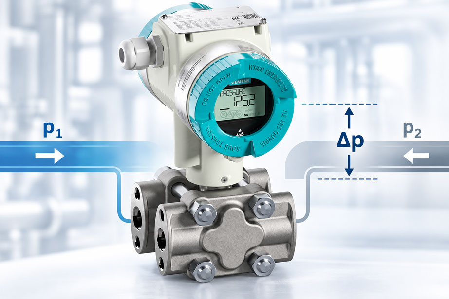
A differential pressure transmitter measures a differential pressure of 0 to 250 mbar in an industrial pipeline. The static line pressure during normal operation is approximately 40 bar. During routine calibration in the workshop, the instrument is checked using a precision pressure calibrator. Both process connections are at ambient pressure or are exposed only to the pressure required for the respective differential pressure test point. The results are satisfactory: zero point and span are within the specified tolerances.
However, after reinstallation in the plant, the transmitter already shows a small offset at zero differential pressure. The indicated differential pressure under a known operating condition also deviates from the expected values.
Is the transmitter defective? Was the calibration inaccurate? Or does the high static line pressure change the characteristics of the differential pressure measuring cell?
This question is of considerable importance for the process industry, energy supply, chemical industry, plant engineering, and industrial calibration laboratories. A differential pressure transmitter frequently measures a relatively small pressure difference while a significantly higher static pressure acts simultaneously on both sides.
A typical example is a measuring range of 0 to 250 mbar at a static operating pressure of 40 bar. The required differential pressure measurement therefore represents only a small fraction of the total pressure level to which the measuring cell is exposed.
Static line pressure acts on both process connections. Ideally, its influence would cancel out completely so that only the difference between the high-pressure and low-pressure sides is measured. In practice, however, design-related influences can cause zero-point shifts or changes in measurement span.
The magnitude of these influences depends on the measuring cell technology, static pressure, configured differential pressure range, and manufacturer-specific compensation. Some transmitters have automatic or factory-applied correction for static pressure effects. Other versions provide additional adjustment or compensation procedures.
Calibration at ambient pressure can therefore confirm the function and accuracy under the selected test conditions, but it does not necessarily detect all errors occurring under the actual static operating pressure.
For realistic verification, a test setup is required in which both sides of the differential pressure transmitter are subjected to a suitable common base pressure. In addition, a defined small differential pressure is generated and measured using an appropriate reference system.
Safe pressure handling is particularly important. A differential pressure transmitter designed for a static operating pressure of 40 bar must not automatically be subjected to a differential pressure of 40 bar. The permissible static pressure loading and the maximum permissible one-sided differential pressure loading are separate technical limits.
This technical article explains the physical principles of static pressure effects, describes the requirements for a suitable calibration setup, and shows how zero point, span, and characteristic curve deviation can be tested under realistic operating conditions.
A detailed calculation example illustrates how a small zero-point shift and an additional span error influence the 4-to-20-mA output signal. Reference instruments, pressure stabilization, measurement uncertainty, HART parameterization, test procedures, typical errors, and documentation of results are also covered.
Table of Contents
- Measurement Task and Typical Problems with Static Line Pressure
- Operating Principle of a Differential Pressure Transmitter
- Distinguishing Static Line Pressure from Differential Pressure
- Understanding the Effects of Static Pressure on Zero Point and Span
- Comparing Calibration at Ambient Pressure and Operating Pressure
- Test Setup with Common Static Pressure Application
- Selecting Suitable Pressure References and Calibration Instruments
- Practical Example: Calculating Zero-Point Shift and Span Error at 40 bar
- Testing the Zero Point Under Static Line Pressure
- Testing Span and Characteristic Curve Under Operating Pressure
- Pressure Stabilization, Temperature, and Settling Time
- Correctly Handling High-Pressure Side, Low-Pressure Side, and Manifold
- Test Medium, Filling, and Hydrostatic Pressure Differences
- 4-to-20-mA Output, HART, and Digital Measured Values
- Distinguishing Calibration, Zero Adjustment, and Sensor Trim
- Measuring Range, Turndown, and Static Pressure Resistance
- Measurement Uncertainty at High Static Line Pressure
- Calibration Report and Reproducible Documentation
- Pressure Safety, Explosion Protection, and Relevant Standards
- Systematic Testing and Calibration Procedure
- Typical Fault Symptoms and Targeted Diagnostics
- Suitable ICS Products for Differential Pressure Calibration
- Conclusion: Testing Zero Point and Span Under Realistic Conditions
- Frequently Asked Questions About Differential Pressure Calibration
1. Measurement Task and Typical Problems with Static Line Pressure
A differential pressure transmitter measures the pressure difference between two process connections. These are normally designated as the high-pressure side and low-pressure side, or H and L.
The actual static operating pressure can be considerably higher than the measured differential pressure.
Typical applications include:
- Flow measurement using differential pressure primary elements and orifice plates.
- Differential pressure measurement across filters and strainers.
- Monitoring pumps and compressors.
- Level measurement using hydrostatic differential pressure.
- Measurement of pressure losses in pipelines.
- Monitoring heat exchangers.
- Process pressure measurements with small differential pressure spans.
- Measurements on closed, pressurized vessels.
1.1 Typical Calibration Conditions
During a simple workshop test, the high-pressure side of the transmitter is connected to a pressure reference. The low-pressure side is maintained at a defined reference pressure, such as ambient pressure.
The required differential pressure test points are established by increasing the pressure on the high-pressure side.
This method is suitable for certain testing tasks and can be used to evaluate the static characteristic curve of the differential pressure transmitter under the given pressure conditions.
However, it does not necessarily reproduce the static operating pressure of the process plant.
1.2 Calibration Under Operating Conditions
If the transmitter is also to be tested under its actual static line pressure, the corresponding pressure conditions must be established in both measuring chambers.
The small differential pressure is then generated in addition to the common pressure level.
This makes the measurement more demanding because both the high static pressure and the small differential pressure must be controlled accurately and safely.
1.3 Objective of the Investigation
Such a test is intended to determine, in particular:
- Does the zero point change as static pressure increases?
- Does sensitivity or measurement span change?
- Is the characteristic curve sufficiently linear under operating pressure?
- Do increasing and decreasing test points produce different results?
- Does the measured value remain constant after sufficient stabilization?
- Is manufacturer-specific compensation required?
- Are the specified tolerances met under actual operating conditions?
1.4 Calibration and Adjustment
Calibration determines and documents measurement deviations.
Adjustment, on the other hand, changes a setting or device characteristic curve with the aim of reducing the deviation.
These procedures must be clearly distinguished both in the testing process and in the documentation.
2. Operating Principle of a Differential Pressure Transmitter
A differential pressure transmitter measures the difference between two applied pressures.
The fundamental measured quantity is:
Δp = pH – pL
Here, pH represents the pressure at the high-pressure connection and pL the pressure at the low-pressure connection.
2.1 Measuring Cell
Many industrial differential pressure transmitters use a measuring diaphragm or another suitable pressure-sensitive sensor structure.
The applied pressure difference causes a measurable deformation or another physically detectable change.
The sensor electronics convert this into a pressure value.
2.2 Common Pressure
If the same pressure is applied to both process connections, the ideal differential pressure is zero.
For example:
pH = 40.00 bar
pL = 40.00 bar
Δp = 0.00 bar
Under suitable conditions, the instrument should indicate the defined zero value in accordance with its specifications.
2.3 Differential Pressure at a High Pressure Level
If the pressure on the high-pressure side increases slightly while the low-pressure side remains constant, a small differential pressure develops.
For example:
pH = 40.10 bar
pL = 40.00 bar
Δp = 0.10 bar = 100 mbar
In this example, the transmitter measures a differential pressure of 100 mbar at a static line pressure of approximately 40 bar.
2.4 Output Signal
A commonly used output signal is 4 to 20 mA.
For linear scaling from 0 to 250 mbar, the idealized relationship is:
I = 4 mA + 16 mA · Δp / 250 mbar
At 0 mbar, the ideal current is 4 mA; at 125 mbar, it is 12 mA; and at 250 mbar, it is 20 mA.
2.5 Additional Functions
Modern differential pressure transmitters may feature temperature compensation, digital communication, diagnostics, and different output characteristics.
Particularly in flow measurements, the output signal can be configured to be linear with differential pressure or square-root-extracted to represent flow.
For calibration, it is therefore necessary to know which measured quantity and output characteristic are actually configured.
3. Distinguishing Static Line Pressure from Differential Pressure
A fundamental requirement for calibration is a clear distinction between static line pressure and differential pressure.
3.1 Differential Pressure
Differential pressure is the pressure difference between the two process pressures.
Δp = pH – pL
It can be very small even when both process pressures are at a high pressure level.
3.2 Static Line Pressure
In differential pressure applications, static line pressure refers to the common pressure level under which the measuring cell operates.
Depending on the calculation and device model, either the pressure on a defined reference side or the mean pressure on both sides may be used.
For mean pressure:
pstatic,mean = (pH + pL) / 2
The precise definition must be clear for the respective technical specification.
3.3 Example at 40 bar
For the following pressure values:
pH = 40.20 bar
pL = 40.00 bar
the result is:
Δp = 200 mbar
pstatic,mean = 40.10 bar
The mean static pressure is therefore only slightly above 40 bar, while the differential pressure of interest is 200 mbar.
3.4 Small Differential Pressure at a High Pressure Level
The measured differential pressure can be several orders of magnitude smaller than the static line pressure.
This relationship places high demands on the measuring cell, pressure reference, and test setup.
3.5 Pressure Resistance Is Not the Same as Differential Pressure Measuring Range
The maximum permissible static pressure loading does not automatically describe the permissible differential pressure loading.
A transmitter can be designed for high common line pressure while its measuring cell is intended to measure only a small differential pressure.
The limits specified in the data sheet for one-sided overload, static pressure, and measuring range must be checked separately.
4. Understanding the Effects of Static Pressure on Zero Point and Span
Ideally, a differential pressure transmitter should respond only to the actual pressure difference applied.
However, in real measuring cells, static pressure can cause additional mechanical and metrological influences.
4.1 Zero-Point Shift
A zero-point shift occurs when the instrument indicates a differential pressure other than zero even though the actual differential pressure is balanced.
This may be caused, for example, by the mechanical characteristics of the measuring cell or the pressure transmission within the sensor.
With a linear 4-to-20-mA output, the zero-point shift appears as a deviation from the ideal 4-mA value.
4.2 Span Effect
In certain measuring cells, static pressure can influence not only the zero point but also the sensitivity.
The output change between two differential pressure test points may then deviate from the ideal value.
A simple zero-point correction does not necessarily eliminate this span error.
4.3 Manufacturer-Dependent Compensation
Modern transmitters can reduce the influence of static pressure through suitable sensor designs and compensation methods.
For certain instruments, additional adjustment or compensation is provided.
Other configurations do not require separate adjustment because of their measuring cell technology.
4.4 Example from Manufacturer Documentation
For certain Rosemount differential pressure transmitters, Emerson explicitly describes systematic effects of static line pressure on zero point and span.
Special compensation procedures are specified for selected measuring ranges.
These documented correction methods are specific to the instrument and range and must not be applied to other transmitters.
4.5 Distinguishing Offset and Gain
For a simplified analysis, the output characteristic can be described as a linear function:
I = I0 + k · Δp
Here, I0 is the output current at zero differential pressure, while k represents the sensitivity of the current signal to differential pressure.
A change in I0 describes an offset.
A change in k describes a change in span.
Both quantities can be evaluated separately through calibration at multiple test points.
5. Comparing Calibration at Ambient Pressure and Operating Pressure
Calibration at ambient pressure and calibration under high common line pressure may produce different results.
Both tests can be useful, but they must be clearly described and distinguished from one another.
| Feature | Calibration Near Ambient Pressure | Calibration Under Static Line Pressure |
|---|---|---|
| Common pressure level | Low, usually near ambient pressure | Corresponds to the specified test or operating pressure |
| Test differential pressure | Defined small pressure difference | Defined small pressure difference at an additional high pressure level |
| Test setup | Comparatively simple | Suitable high-pressure differential pressure system required |
| Zero-point test | At balanced low pressure | At equal high pressure on both sides |
| Span test | Under the selected low-pressure conditions | Under defined high static pressure conditions |
| Static pressure effect | Not investigated over the intended operating pressure range | Can be determined under the respective test conditions |
| Differential pressure reference | Suitable differential pressure range required | Must also be suitable for high common pressure |
| Safety requirements | Depend on the test conditions | Special requirements for pressure handling and one-sided overload |
| Meaning of the result | Valid for the documented test conditions | Evaluation at the documented static test pressure |
| Main limitation | Does not provide complete verification of the operating pressure effect | Requires a suitable setup, stability, and sufficiently low measurement uncertainty |
5.1 Comparability of Calibration Results
A comparison measurement is particularly informative when the same transmitter is tested at the same differential pressure points before and after changing the static pressure.
This makes it possible to identify changes in zero point and span.
5.2 Documenting Different Test Conditions
The calibration report must clearly state the static pressure at which the test was performed.
A calibration certificate without this information does not automatically demonstrate testing under the line pressure subsequently encountered in the plant.
5.3 Application-Specific Evaluation
Whether additional calibration under static pressure is necessary depends on the measurement task, transmitter, required accuracy, and manufacturer specifications.
The same testing strategy is therefore not fundamentally required for every differential pressure transmitter.
6. Test Setup with Common Static Pressure Application
Testing a differential pressure transmitter under high static line pressure requires a pressure setup designed for this purpose.
The testing concept must simultaneously meet two different requirements:
- Generating and safely maintaining the specified high common pressure level.
- Generating and accurately measuring a substantially smaller difference between the two pressure connections.
6.1 Basic Principle
At zero differential pressure, both connections are at the same defined pressure level.
For a positive differential pressure, a correspondingly small pressure difference is established between the H and L sides.
The actual pressures must remain within all permissible instrument limits.
6.2 Two Pressure Channels
A suitable setup can be implemented using separately controllable pressure channels.
This allows the pressures on both sides to be set independently.
However, using two independent pressure controllers alone does not guarantee a safe test setup.
Particularly during pressurization, controller faults, and depressurization, impermissible differential pressures must be prevented.
6.3 Common Pressure Supply
An alternative test system can provide a common base pressure and additionally generate a small controlled differential pressure.
Such setups can be particularly suitable for recurring differential pressure calibrations under high static pressure.
The specific design must be adapted to the pressure range, medium, and protection requirements.
6.4 Differential Pressure Reference
The reference measurement must detect the small differential pressure with sufficient accuracy.
At the same time, the reference system must be designed for the static pressure applied to both sides.
A simple low-pressure sensor designed only for small pressures relative to ambient pressure must not be exposed to high static pressure without appropriate approval.
6.5 Isolation and Pressure Equalization
Suitable valves and pressure equalization devices may form part of the test setup.
Their functions include establishing defined pressure conditions and preventing impermissible differential loading.
The actual valve operating sequence must comply with the approved test procedure and manufacturer instructions.
6.6 Safety During Depressurization
Pressure must be released in a controlled manner.
An unsuitable depressurization sequence must not cause a high one-sided differential pressure across the measuring cell.
This applies even if both process connections are approved for the static pressure concerned.
6.7 Practical Design
In addition to pressure controllers, a suitable test bench requires appropriate pressure lines, isolation devices, overpressure protection, pressure references, and a suitable data acquisition system.
The entire assembly must be approved for the test medium and the maximum possible pressure conditions.
7. Selecting Suitable Pressure References and Calibration Instruments
The selection of the pressure reference is a major factor in determining the achievable measurement uncertainty.
For a small differential pressure at a high static pressure, distinguishing between the measurement of two individual pressures and direct differential pressure measurement is particularly important.
7.1 Direct Differential Pressure Reference
A suitable differential pressure reference directly measures the difference between the H and L sides.
It must be specified for both the small test differential pressure and the high static pressure.
The accuracy specification must apply to the actual test conditions.
7.2 Two Individual Pressure References
A pressure difference can also be calculated from two separately measured pressures:
Δp = pH – pL
At a pressure level of approximately 40 bar and a differential pressure of only a few millibars, the uncertainties of the two large individual pressure readings can be considerable relative to the difference.
The resulting uncertainty must be determined carefully.
A calculated difference between two highly accurate pressure indications is not automatically a sufficiently accurate differential pressure reference.
7.3 Calibration of Reference Instruments
The reference instruments used must be suitably calibrated and metrologically traceable for the application.
The calibration scope should cover the pressure range actually required and the corresponding operating conditions.
7.4 Electrical Reference
A transmitter with a 4-to-20-mA output additionally requires suitable current measurement.
The uncertainty of the current measuring instrument forms part of the overall calibration uncertainty.
7.5 Automatic Pressure Control
Automatic pressure controllers can improve the reproducibility of test points and reduce operator workload.
The appropriate control configuration and a safe test concept are decisive.
The suitability of the complete system for directly generating a small differential pressure under high static pressure must be evaluated separately.
8. Practical Example: Calculating Zero-Point Shift and Span Error at 40 bar
A differential pressure transmitter is initially tested under low static pressure conditions. A second test is then performed under a static line pressure of approximately 40 bar.
The two tests are intended to demonstrate how zero point and span can change.
The example uses a hypothetical series of measurements so that the calculation can be understood independently of a particular instrument configuration.
8.1 Initial Data and Assumptions
The following explicitly selected assumptions apply:
- Device under test: Differential pressure transmitter with linear output.
- Configured measuring range: 0 to 250 mbar.
- Output signal: 4 to 20 mA.
- First test: Low static pressure.
- Second test: Low-pressure side constant at 40.00 bar gauge.
- High-pressure side: 40.00 bar to 40.25 bar gauge.
- Test points: 0 %, 25 %, 50 %, 75 %, and 100 %.
- Assumed constant operating and ambient temperature.
- Sufficiently stabilized pressure conditions.
- No adjustment between the two tests.
- Assumed linear transmitter characteristic at each static pressure level.
In this simplified test configuration, the mean static pressure increases slightly from 40.00 to 40.125 bar as differential pressure increases. It is therefore not mathematically constant but remains close to the intended line pressure of 40 bar.
To investigate the behavior at an exactly constant mean static pressure, both test pressure sides would have to be changed in a coordinated manner.
8.2 Ideal Current Characteristic
For a linear transmitter with a range of 0 to 250 mbar and an output of 4 to 20 mA:
Iideal = 4 mA + 16 mA · Δp / 250 mbar
This gives the following ideal current values:
- 0 mbar: 4.00 mA.
- 62.5 mbar: 8.00 mA.
- 125.0 mbar: 12.00 mA.
- 187.5 mbar: 16.00 mA.
- 250.0 mbar: 20.00 mA.
8.3 First Calibration at Low Static Pressure
For this example, it is assumed that the transmitter produces exactly the ideal current values at low static pressure.
This assumption serves as the basis for comparison.
Under these idealized conditions, the instrument exhibits neither a zero-point error nor a span error.
8.4 Second Calibration at 40 bar Line Pressure
The following hypothetical measured values are assumed for the second test:
- 0 mbar: 4.064 mA.
- 62.5 mbar: 8.044 mA.
- 125.0 mbar: 12.024 mA.
- 187.5 mbar: 16.004 mA.
- 250.0 mbar: 19.984 mA.
The assumed measured values show a small positive zero-point shift and a slightly reduced measurement span.
| Differential Pressure | Ideal Signal | Measured Signal | Current Deviation | Equivalent Pressure Deviation |
|---|---|---|---|---|
| 0 mbar | 4.000 mA | 4.064 mA | +0.064 mA | +1.0000 mbar |
| 62.5 mbar | 8.000 mA | 8.044 mA | +0.044 mA | +0.6875 mbar |
| 125.0 mbar | 12.000 mA | 12.024 mA | +0.024 mA | +0.3750 mbar |
| 187.5 mbar | 16.000 mA | 16.004 mA | +0.004 mA | +0.0625 mbar |
| 250.0 mbar | 20.000 mA | 19.984 mA | -0.016 mA | -0.2500 mbar |
8.5 Calculate the Zero-Point Error
At an actual differential pressure of 0 mbar, the ideal current signal is 4.000 mA.
The measured value is 4.064 mA.
The deviation is:
ΔI0 = 4.064 mA – 4.000 mA
ΔI0 = +0.064 mA
The output current therefore corresponds to an apparent positive pressure difference.
8.6 Convert the Zero-Point Error into Differential Pressure
The current span is 16 mA, and the configured differential pressure span is 250 mbar.
This gives:
Δp0 = ΔI0 / 16 mA · 250 mbar
Δp0 = 0.064 / 16 · 250 mbar
Δp0 = +1.00 mbar
At a common line pressure of 40 bar, the hypothetical transmitter therefore exhibits a zero-point deviation equivalent to a differential pressure of +1.00 mbar.
8.7 Zero-Point Error Relative to the Measurement Span
Relative to the configured differential pressure span of 250 mbar:
ε0 = 1.00 mbar / 250 mbar · 100 %
ε0 = +0.40 %
The zero-point error is therefore +0.40 % of the configured differential pressure span.
8.8 Calculate the Actual Current Span
The current span between the measured lower and upper test points is:
SI = I250 – I0
SI = 19.984 mA – 4.064 mA
SI = 15.920 mA
The ideal current span is 16.000 mA.
The actual current span is therefore 0.080 mA smaller.
8.9 Calculate the Span Error
The relative error of the output span is:
εS = (SI – 16 mA) / 16 mA · 100 %
εS = (15.920 – 16.000) / 16.000 · 100 %
εS = -0.50 %
In this example, the measurement span is reduced by 0.50 % compared with the ideal output span.
8.10 Span Error Expressed as a Pressure Value
Relative to the configured differential pressure span of 250 mbar, the span difference corresponds to:
ΔpS = -0.005 · 250 mbar
ΔpS = -1.25 mbar
This describes the difference between the actual and ideal span, not the total error at the upper test point.
8.11 Error at the Upper Test Point
At the upper test point, two effects act simultaneously:
- Positive zero-point shift equivalent to +1.00 mbar.
- Reduced span equivalent to -1.25 mbar.
The total deviation is therefore:
Δp250 = +1.00 mbar – 1.25 mbar
Δp250 = -0.25 mbar
This result corresponds to the pressure deviation calculated from the measured current signal of 19.984 mA.
8.12 Simplified Characteristic Equation
The hypothetical current characteristic at a static line pressure of 40 bar can be expressed as:
I(Δp) = 4.064 mA + 15.920 mA · Δp / 250 mbar
This equation illustrates both error components:
The constant output term of 4.064 mA describes the zero-point shift.
The reduced output span of 15.920 mA describes the span error.
8.13 Why Zero-Point Correction Alone Is Not Always Sufficient
If only the zero point is shifted, the output value at zero differential pressure can be corrected.
However, the reduced sensitivity remains unchanged.
After a simple offset correction, the example would therefore still have an output span that is smaller than the ideal value.
For demanding calibration under static line pressure, the entire relevant characteristic curve must therefore be tested.
8.14 Limitations of the Calculation Example
All measured values and error quantities are freely selected.
They represent neither the guaranteed accuracy nor the actual behavior of any particular Siemens, WIKA, or Rosemount transmitter.
The real characteristic curve may additionally exhibit nonlinearity, hysteresis, and temperature effects.
The calculation example illustrates only how zero-point and span changes can be evaluated separately under high static pressure.
9. Testing the Zero Point Under Static Line Pressure
Zero-point testing under static line pressure is one of the most important investigations in the corresponding calibration procedure.
9.1 Establish Zero Differential Pressure
For zero-point testing, the same defined pressure must be applied to both process connections.
At a required static test pressure of 40 bar, this means:
pH = 40 bar
pL = 40 bar
Δp = 0 mbar
9.2 Ensure Pressure Equalization
Pressure equalization must be established using the test setup designed for that purpose.
The transmitter’s permissible differential pressure loading must not be exceeded during this process.
9.3 Allow Sufficient Stabilization
A settling period may be required after changing the static pressure.
This depends, among other factors, on the measuring cell, pressure transmission medium, and temperature.
The zero value should only be evaluated after sufficient stabilization.
9.4 Record Zero-Point Deviation
The indicated or transmitted value is compared with the actual reference differential pressure of zero.
The deviation must be documented in the corresponding pressure unit and, where applicable, as a percentage of the configured measurement span.
9.5 Repeat at Different Static Pressures
If the influence of static pressure is to be investigated, zero-point tests can be performed at several defined pressure levels.
The selected pressures must remain within the permissible instrument limits.
This allows the dependence of the zero point on static pressure to be described.
9.6 Zero-Point Correction
Zero adjustment must only be performed according to the manufacturer’s specified procedure.
For certain instruments, adjustment under balanced operating pressure is provided.
The exact procedure depends on the measuring cell and instrument configuration.
Such an adjustment must not automatically be considered equivalent to complete span calibration.
10. Testing Span and Characteristic Curve Under Operating Pressure
In addition to the zero-point test, the transmitter’s sensitivity under high static pressure must also be investigated where required.
10.1 Multiple Differential Pressure Test Points
Suitable test points within the configured differential pressure measuring range are used to check the characteristic curve.
The number and distribution of test points depend on the intended calibration procedure and accuracy requirements.
10.2 Increasing Differential Pressure Values
The test points are approached according to a defined procedure and documented after sufficient stabilization.
At high static pressure, the pressure difference between the two process connections must remain controlled.
10.3 Decreasing Differential Pressure Values
Testing with decreasing differential pressure values can provide additional information about transmitter behavior.
This is particularly important for evaluating possible hysteresis effects.
10.4 Characteristic Curve Deviation
The deviation determined at each test point describes the difference between the value output by the transmitter and the reference value.
Depending on the calibration procedure, these deviations can be documented as current deviations, pressure deviations, or percentages.
10.5 Span Error
The span can be determined from the difference between the lower and upper output values.
This makes it possible to evaluate changes in sensitivity independently of a simple zero-point offset.
10.6 Nonlinearity
If the measurement deviations between individual test points cannot be described by a simple linear change in the characteristic curve, additional nonlinearity is present.
This must be considered during evaluation.
10.7 Manufacturer-Specific Compensation
Certain transmitters provide functions for compensating the influence of static pressure on span.
The application of these functions must be based on the respective manufacturer instructions.
There is no universal correction formula for all differential pressure transmitters.
11. Pressure Stabilization, Temperature, and Settling Time
Reliable calibration requires sufficiently stable test conditions.
At high static pressure and simultaneously small differential pressures, even minor changes in pressure or temperature can influence the test.
11.1 Stability of Common Pressure
The static pressure must be maintained with sufficient stability within the intended test range.
Fluctuations can influence the zero point or differential pressure control.
11.2 Stability of Differential Pressure
The stability of the small differential pressure is particularly important.
For a measuring span of 250 mbar, for example, fluctuations in the millibar range are already significant.
11.3 Thermal Settling
Pressure changes can cause temperature changes in the test medium and the components involved.
These effects may need to subside before evaluation.
11.4 Measuring Cell Temperature
The transmitter may exhibit additional temperature-dependent measurement deviations.
The actual instrument temperature should therefore remain within the specified test range and be sufficiently stable.
11.5 Leak Tightness of the Test Setup
Leaking connections can cause pressure drift.
With small differential pressures, even minor changes in the pressure relationship between the two sides can cause a significant measurement deviation.
11.6 Stabilization Criterion
The required stabilization must not be evaluated solely on the basis of an arbitrary waiting time.
A suitable test procedure should define the conditions under which the pressure and output signal are considered sufficiently stable.
11.7 Reproducibility
For recurring calibrations, stabilization criteria and measurement times should be applied as consistently as possible.
This improves the comparability of results.
12. Correctly Handling High-Pressure Side, Low-Pressure Side, and Manifold
Correct assignment of pressure connections is particularly important during differential pressure calibration.
12.1 H and L Connections
The H connection usually identifies the high-pressure side, while L identifies the low-pressure side.
The specific markings must be checked on the instrument or in the manufacturer’s instructions.
12.2 Valve Manifolds
Three-valve or five-valve manifolds are frequently used in process plants.
Depending on their configuration, they provide isolation, pressure equalization, and additional service functions.
The actual operating principle of the manifold used must be understood.
12.3 Protecting the Measuring Cell
Impermissible differential pressure loading must not occur during pressurization or depressurization.
A suitable pressure equalization function and an approved procedure can help protect the measuring cell.
12.4 Different Pressure Connections
The process connections must be mechanically compatible with the test equipment and its sealing principle.
Adapters, pressure lines, and valves require appropriate pressure and media approvals.
12.5 Diaphragm Seals
Additional influences are possible with differential pressure transmitters equipped with diaphragm seals and capillary lines.
Fill fluid, height differences, temperature, and the system configuration can affect the zero-point position.
Such a measuring point must be evaluated based on its complete configuration.
12.6 Impulse Lines
Impulse lines can introduce additional errors in installed transmitters.
These include trapped gas bubbles, unequal liquid columns, deposits, or blocked connections.
An unusual measurement during operation does not therefore necessarily indicate a fault in the transmitter itself.
13. Test Medium, Filling, and Hydrostatic Pressure Differences
The test medium influences both safety and the metrological characteristics of the test setup.
13.1 Pneumatic Calibration
For suitable applications, pressure tests can be performed using gaseous media.
The permissible pressure media, stored pressure energy, and required safety measures must be considered.
13.2 Hydraulic Calibration
Liquid test media may be required or suitable for other pressure ranges and instruments under test.
Compatibility with the measuring cell and pressure transmission systems must be considered.
13.3 Identical Pressure Transmission Conditions
Both pressure sides should have comparable and defined conditions according to the intended test procedure.
Different filling conditions can cause additional influences.
13.4 Hydrostatic Pressure Difference
With liquid-filled pressure lines, height differences between the reference instrument and the device under test can be relevant.
For a stationary liquid:
Δph = ρ · g · Δh
Here, ρ is the density, g is gravitational acceleration, and Δh is the relevant height difference.
13.5 Significance for Small Differential Pressures
Even a small hydrostatic pressure difference can cause a significant deviation when working with narrow differential pressure ranges.
Measurement heights and filling conditions should therefore be documented and corrected where necessary.
13.6 Venting
Trapped gas bubbles can influence pressure behavior in liquid-filled measuring systems.
Any required venting must be performed according to the approved test procedure.
13.7 Avoiding Contamination
The test medium must not damage or impermissibly contaminate the pressure cell, diaphragms, or filling systems.
Suitable separation and protective measures may be necessary for sensitive or media-isolated systems.
14. 4-to-20-mA Output, HART, and Digital Measured Values
Differential pressure measurement and the electrical output signal are related, but they must be evaluated separately during calibration.
14.1 Analog Current Signal
With linear scaling, a differential pressure corresponds to a defined current between 4 and 20 mA.
Correct current measurement is therefore part of the calibration.
14.2 Digital Process Variable
With a smart transmitter, the internally calculated differential pressure can also be read digitally.
This information can help distinguish measuring cell influences from analog output errors.
14.3 HART Communication
Depending on the instrument, HART can be used to read or configure measured values, measuring ranges, parameterization, diagnostic information, and certain adjustment functions.
The available functions depend on the manufacturer and instrument.
14.4 Sensor Characteristic and Current Output
Changing the sensor trim is not the same as adjusting the analog current output.
During diagnostics, it is necessary to distinguish whether the digital pressure value itself is incorrect or whether only the analog signal transmission deviates.
14.5 Square-Root Output
In flow measurement using a differential pressure primary element, a square-root characteristic may be configured.
In this case, the output signal is not linearly proportional to differential pressure.
The test must either consider the configured output characteristic or evaluate the directly measured differential pressure variable according to the approved procedure.
14.6 Fault Current and Diagnostics
A diagnostic or fault current must be distinguished from a normal process measurement value.
The transmitter’s fault strategy must be documented during calibration.
15. Distinguishing Calibration, Zero Adjustment, and Sensor Trim
In practice, the terms calibration and adjustment are frequently used interchangeably.
For traceable evaluation, they should be clearly distinguished.
15.1 Calibration
During calibration, the indications or output values of the device under test are compared with reference values.
The deviations determined are documented.
15.2 Zero Adjustment
Zero adjustment changes the zero-point position of the measuring system.
For differential pressure transmitters, it may be performed under specified conditions with equal pressure applied to both process connections.
15.3 Sensor Trim
Sensor trim can change the internal relationship between the sensor measurement value and the reference pressure.
The functions and conditions provided for this purpose depend on the manufacturer.
15.4 Span Adjustment
Span adjustment concerns sensitivity or the relationship between differential pressure and the output signal.
It must not be performed without understanding the specific instrument function.
15.5 Analog Output Trim
A separate output trim concerns the current output of the transmitter.
An incorrect analog output can potentially be corrected without changing the actual pressure measuring cell.
15.6 As-Found and As-Left Documentation
If an adjustment is performed, the results before and after the adjustment should be clearly documented separately.
This ensures that it remains possible to determine whether the original measurement deviation met the specified requirements.
15.7 Adjustment Under Static Pressure
Adjustment under operating pressure may be appropriate or specified by the manufacturer for certain instruments.
However, it is not a universal standard procedure for every differential pressure transmitter.
Span correction in particular must follow the specific manufacturer’s procedure.
16. Measuring Range, Turndown, and Static Pressure Resistance
Several pressure and accuracy specifications must be considered when selecting a differential pressure transmitter.
16.1 Differential Pressure Measuring Range
The differential pressure measuring range describes the span over which the transmitter is intended to measure the required pressure difference.
For example, 0 to 250 mbar.
16.2 Static Operating Pressure
The permissible static operating pressure describes the pressure loading under which the measuring cell may operate according to its specification.
This value can be significantly higher than the differential pressure measuring range.
16.3 One-Sided Overpressure Capability
One-sided overpressure capability is a separate instrument characteristic.
It must be considered particularly during installation, commissioning, and calibration.
16.4 Turndown
Turndown describes the ratio between an upper available measurement span and a smaller configured span within the manufacturer’s specifications.
With highly reduced spans, certain error components can become more significant relative to the configured span.
16.5 Errors Relative to URL and Span
Manufacturers may express accuracy and influence specifications relative to the upper range limit of the measuring cell or to the configured measurement span.
These specifications must not be confused.
A percentage of the sensor’s upper range limit can represent a different absolute pressure deviation from the same percentage of the configured span.
16.6 Suitable Measuring Cell
For demanding differential pressure measurements, not only the permissible static pressure but also its influence on measurement accuracy should be considered.
The specific sensor and measuring range configuration is therefore decisive.
17. Measurement Uncertainty at High Static Line Pressure
Determining measurement uncertainty is particularly demanding when calibrating differential pressure under high static pressure.
The small differential pressure must be verified with sufficient accuracy even though both sides are at a considerably higher pressure level.
17.1 Reference Uncertainty
The uncertainty of the differential pressure reference used must be considered for the actual test range.
It is particularly important to establish whether its specification also applies at the static pressure used.
17.2 Static Pressure Effect on the Reference
Not only the device under test but also the reference may be influenced by the common pressure.
This influence must be known or sufficiently limited.
17.3 Two Individual Pressure Measurements
If differential pressure is calculated from two individual pressure references, their uncertainties may propagate into the difference.
For uncorrelated measurement errors, the combined standard uncertainty of the difference is simplified as:
u(Δp) = √(u(pH)² + u(pL)²)
For correlated contributions, covariance must also be considered.
A general assumption of complete error cancellation is not permissible.
17.4 Differential Pressure Stability
Fluctuations between the two pressure sides can influence test results.
Stability must therefore be measured and evaluated under the actual test conditions.
17.5 Current Measurement
The uncertainty of the electrical measuring instrument must be included when evaluating an analog transmitter output.
17.6 Repeatability and Hysteresis
Different results when repeatedly setting the same test point, as well as during increasing and decreasing pressure values, can cause additional uncertainty contributions.
17.7 Hydrostatic Correction
In liquid-filled test systems, height differences and changes in density can influence the pressure reference.
These contributions must also be considered where applicable.
17.8 Temperature
Ambient temperature, medium temperature, and thermal settling processes can influence both the device under test and the reference.
17.9 Expanded Measurement Uncertainty
A combined standard uncertainty can be determined from the relevant standard uncertainty contributions.
The expanded measurement uncertainty is obtained by multiplying by a suitable coverage factor:
U = k · uc
The coverage factor used and the associated coverage probability must be stated according to the procedure applied.
17.10 Reference to Standards and Guidelines
DKD-R 6-1 and EURAMET cg-17 are among the relevant metrological guidelines for calibrating pressure measuring instruments.
For calibrations performed according to ISO/IEC 17025, the applicable requirements for procedures, traceability, and measurement uncertainty must also be considered.
18. Calibration Report and Reproducible Documentation
A meaningful calibration report must describe the test conditions in sufficient detail to allow the results to be traced and evaluated later.
18.1 Device Under Test Information
The following information in particular should be documented:
- Manufacturer and instrument model.
- Serial number.
- Measuring cell configuration.
- Configured differential pressure measuring range.
- Maximum permissible static operating pressure.
- Output signal and characteristic curve.
- Device or firmware version used, where relevant.
18.2 Test Setup
The test setup used should be clearly described.
This includes pressure supply, controllers, references, pressure lines, valves, and relevant connection conditions.
18.3 Static Test Pressure
Specifying the static test pressure is particularly important.
If it varies throughout the measurement series, the definition used and the actual pressure profile must be traceable.
18.4 Differential Pressure Test Points
All test points applied and their associated reference values must be documented.
18.5 Electrical Measurements
The measured current signals and any digital process values should be clearly assigned to the respective test points.
18.6 Zero-Point and Span Errors
The deviations can be evaluated separately as zero-point errors, span errors, and individual test-point deviations.
18.7 Test Conditions
Temperature, test medium, stabilization, and relevant influencing factors must be documented where required.
18.8 Measurement Results Before and After Adjustment
If an adjustment has been performed, the results before and after the change must be clearly distinguishable.
18.9 Traceability and Measurement Uncertainty
The reference instruments and calculated measurement uncertainty must be documented according to the calibration procedure used.
18.10 Evaluation
A pass/fail evaluation requires clearly defined tolerances and a suitable decision rule.
The evaluation must not be based solely on a general manufacturer specification without reference to the specific measuring cell and actual test conditions.
19. Pressure Safety, Explosion Protection, and Relevant Standards
High static test pressures place particular demands on the calibration setup.
19.1 Pressure Resistance of Components
All pressure-bearing components must be designed for the maximum possible pressure conditions.
These include controllers, references, pressure lines, valves, adapters, and connections.
19.2 One-Sided Pressure Loading
A high permissible common pressure must not be confused with the permissible one-sided differential pressure loading.
The measuring cell must be protected against impermissible differential pressures according to manufacturer specifications.
19.3 Pressure Equalization
Suitable pressure equalization can help prevent critical pressure conditions.
The required valve and control operations must be defined in a verified procedure.
19.4 Stored Pressure Energy
The stored pressure energy can be considerable when gaseous test media are used.
The choice of test medium and protective measures must therefore be appropriate for the application.
19.5 Electrical Safety
The applicable electrical safety requirements must be observed when measuring current, supplying power, and communicating with the transmitter.
19.6 Hazardous Areas
When working in hazardous areas, the specific device approval, electrical connection conditions, and approved working procedure must be observed.
The availability of an intrinsically safe instrument version does not mean that every calibration configuration is suitable for the hazardous area concerned.
19.7 Relevant Standards and Guidelines
Depending on the application, the following references are particularly relevant:
- DKD-R 6-1 for the calibration of pressure measuring instruments.
- EURAMET cg-17 for the calibration of electromechanical and mechanical pressure measuring instruments.
- ISO/IEC 17025 for competence requirements applicable to testing and calibration laboratories.
- The applicable pressure equipment and occupational safety regulations.
- The manufacturer’s instructions for the device under test and calibration equipment.
The actual applicability and required testing or accreditation scope must be verified for the specific measurement task.
20. Systematic Testing and Calibration Procedure
A documented test procedure is recommended for repeatable differential pressure calibration under static line pressure.
The following steps describe the metrological organization of a suitable test system. Actual valve and pressure control operations must follow the approved safety procedure.
- Define the measurement task: Determine the differential pressure range, static test pressure, and required measurement uncertainty.
- Identify the device under test: Document manufacturer, model, measuring cell, serial number, and output characteristic.
- Check instrument limits: Determine the maximum permissible static pressure and one-sided differential pressure capability.
- Check manufacturer procedures: Consider specifications regarding static pressure effects and possible compensation functions.
- Select the test bench: Provide suitable and safely controllable pressure regulation for both pressure sides.
- Check the differential pressure reference: Confirm suitability for the measurement span and common test pressure.
- Select the test medium: Consider media compatibility, safety, and required pressure transmission.
- Inspect the setup: Check pressure lines, valves, adapters, and connections.
- Check protective devices: Confirm measures against impermissible pressure conditions and one-sided overload.
- Prepare electrical measurement: Check current measurement, power supply, and HART communication where applicable.
- Record output parameterization: Document measuring range, linear or square-root characteristic, and fault strategy.
- Perform the first comparison test: If specified, record the characteristic curve under low static pressure conditions.
- Establish the common test pressure: Apply the specified static pressure using the approved pressure control and safety procedure.
- Check pressure stability: Evaluate settling and temperature conditions.
- Record the zero point: Document the output value when equal pressure on the H and L sides has been verified.
- Apply differential pressure test points: Set the specified small pressure differences using suitable control and reference equipment.
- Document the increasing series: Record reference pressure, static pressure level, and output signal.
- Document the decreasing series: Check hysteresis and repeatability according to the calibration procedure.
- Recheck the zero point: Evaluate possible permanent or time-dependent changes.
- Release pressure in a controlled manner: Safely depressurize the system according to the approved procedure.
- Calculate measurement deviations: Evaluate zero point, characteristic curve, and span separately.
- Determine measurement uncertainty: Consider the reference, static pressure, stability, electrical measurement, and other influencing factors.
- Perform adjustment if necessary: Only according to manufacturer instructions and with clear documentation.
- Perform verification after adjustment: If adjustment was performed, recheck the relevant test points.
- Prepare the calibration report: Document test conditions, results, uncertainty, and any conformity assessment.
Such a procedure enables systematic evaluation of the transmitter under defined static pressure conditions.
However, it does not replace the pressure safety approval required for the specific test bench.
21. Typical Fault Symptoms and Targeted Diagnostics
When unusual differential pressure values occur, a distinction must be made between instrument errors, test setup influences, and actual process conditions.
Particularly under high static line pressure, different causes can produce similar measurement deviations.
| Fault Symptom | Possible Cause | Suitable Diagnostic Action |
|---|---|---|
| Zero point correct at ambient pressure but shifted at 40 bar | Static pressure effect on the measuring cell | Compare zero point at defined common pressure levels |
| Span changes under high static pressure | Static pressure effect on sensor sensitivity | Perform a multipoint test under operating pressure and check manufacturer specifications |
| Zero point changes after depressurization | Hysteresis, thermal influence, or possible overload | Investigate test sequence, pressure profile, and instrument condition |
| Pressure reference fluctuates at small differences | Insufficient control stability or unsuitable reference | Check reference measurement chain and pressure stabilization |
| Measured value drifts after pressurization | Thermal settling or leakage | Evaluate temperature, leak tightness, and stabilization |
| Large difference between two pressure references | Calibration deviation, different pressure references, or hydrostatic influence | Compare pressure type, connection height, and uncertainty budget |
| Digital differential pressure value correct, mA signal incorrect | Analog output, current scaling, or electrical measurement chain | Check digital process variable and current output separately |
| Measured current does not change linearly with differential pressure | Square-root characteristic or another configured function | Check output characteristic and HART parameters |
| Measurement correct in workshop but deviates during operation | Static pressure, impulse line, temperature, or installation conditions | Systematically compare operating and calibration conditions |
| Different results at increasing and decreasing test points | Hysteresis of the measuring cell or test setup | Perform repeated measurement series under defined conditions |
| Zero-point correction improves only the lower measuring range | Additional span or characteristic curve error | Evaluate multipoint testing and manufacturer-specific trim |
| Implausible differential pressure after maintenance | Incorrect connection assignment, gas bubbles, changed liquid columns, or valve position | Check measuring point setup and process lines according to the approved procedure |
The listed causes are possible diagnostic approaches and do not constitute definitive fault identification.
In safety-related applications, abnormalities must be evaluated according to the specified testing and protective procedures.
22. Suitable ICS Products for Differential Pressure Calibration
ICS Schneider Messtechnik offers various precision pressure controllers, pressure calibrators, pressure reference modules, and process calibrators for industrial calibration applications.
When calibrating differential pressure transmitters under high static pressure, a distinction must be made between pressure generation, pressure control, differential pressure reference measurement, and electrical measurement.
A suitable combination of these functions is required for complete testing.
22.1 Druck PACE6000E – Dual-Channel Precision Pressure Controller
The Druck PACE6000E is a modular dual-channel precision pressure controller for demanding laboratory, test bench, and production applications.
The instrument can be equipped with two interchangeable PACE CM control modules.
Documented features include:
- Dual-channel controller chassis.
- Independently controllable pressure channels in suitable configurations.
- Pressure ranges from 25 mbar to 210 bar across the available module variants.
- Very high control and measurement accuracy depending on the selected CM module.
- Precision control modules CM0, CM1, CM2, and CM3.
- Automated pressure control.
- Various digital communication interfaces.
- Suitable for automated calibration and test bench applications.
With its two pressure channels, the PACE6000E is particularly interesting for developing suitable test benches requiring two defined pressure levels.
However, for differential pressure calibration under high static pressure, the specific module selection, differential pressure reference, pressure handling, and protection concept must be checked.
Dual-channel operation alone does not guarantee that a small differential pressure can be generated safely and with the required uncertainty at a high common line pressure without additional measures.
A suitable safety and control strategy must prevent impermissible differential pressure conditions, particularly during dynamic control operations.
Further Information: Druck PACE6000E at ICS Schneider Messtechnik
22.2 Druck PACE5000E – Single-Channel Precision Pressure Controller
The Druck PACE5000E is a modular precision pressure controller with one control channel.
It is suitable for demanding calibration tasks in laboratories, production, and test benches.
Documented features include:
- Single-channel pressure controller chassis.
- Interchangeable PACE CM control modules.
- Pressure ranges from 25 mbar to 210 bar.
- High pressure control stability.
- Automatic adjustment of test pressure setpoints.
- Different accuracy classes depending on the module.
- Digital interfaces for test bench integration.
The PACE5000E can be used as part of a suitable pressure test setup.
However, a single control channel is not automatically sufficient to generate both the high static pressure and an independently adjustable small differential pressure on a two-chamber transmitter.
An appropriate additional pressure and reference arrangement must be provided for this purpose.
Further Information: Druck PACE5000E at ICS Schneider Messtechnik
22.3 Druck DPI610E – Portable Pressure Calibrator
The Druck DPI610E combines pressure generation, pressure measurement, and electrical calibration functions in a portable instrument.
It is suitable for numerous testing and calibration tasks on industrial pressure transmitters.
Documented features include:
- Integrated pneumatic pressure generation up to 35 bar in suitable configurations.
- Hydraulic versions for pressure ranges up to 1,000 bar.
- Pressure measurement accuracy up to 0.025 % of full scale according to the specified configuration.
- HART communication.
- Electrical measurement and calibration functions.
- Data storage and documenting functions.
- Optional connection of external PM700E pressure reference modules.
- Suitable intrinsically safe versions.
The DPI610E is particularly interesting for mobile calibration tasks and on-site testing of pressure transmitters.
However, investigating a differential pressure transmitter under high static line pressure requires an appropriate additional pressure arrangement for pressurizing both sides.
An integrated pressure pump alone does not replace a differential pressure reference suitable for high common pressure.
Further Information: Druck DPI610E at ICS Schneider Messtechnik
22.4 Druck PM700E – External Pressure Reference Modules
The Druck PM700E series includes external pressure reference modules for use with the DPI610E.
They extend the available measurement ranges and allow different pressure references to be used.
Documented features include:
- Various pressure measurement ranges from 25 mbar to 1,400 bar across the product family.
- Versions for gauge pressure, absolute pressure, differential pressure, and barometric pressure.
- Accuracy variants down to ±0.025 % FS.
- Plug-and-play recognition by the DPI610E.
- Individually stored calibration data.
- Various pressure connection options.
- Suitable versions for hazardous areas.
The available differential pressure versions are particularly interesting for corresponding differential pressure calibration tasks.
However, for an application at 40 bar or another high common pressure, it must be verified that the selected differential pressure module is explicitly suitable for this static pressure on both connections.
The highest pressure measurement range of the entire module series must not be equated with the permissible static loading of every differential pressure module.
Further Information: Druck PM700E at ICS Schneider Messtechnik
22.5 Druck DPI620 Genii – Multifunction Process Calibrator
The Druck DPI620 Genii is a modular multifunction calibrator for electrical and pressure-related process measurements.
It can be combined with suitable pressure modules and pressure base stations.
Documented features include:
- Electrical process calibration functions.
- Various instrument versions with HART and additional communication functions.
- Modular connection of pressure measurement modules.
- Pressure ranges depending on module and base station.
- Measurement and simulation of industrial standard signals.
- Documentation and data processing functions.
- Expansion with suitable manual or automatic pressure generation systems.
The DPI620 Genii is particularly useful for electrical testing of smart differential pressure transmitters.
Depending on the configuration, it allows verification of output current, parameterization, and digital process values.
Pressurizing both transmitter sides under high static pressure requires a separately suitable setup.
Further Information: Druck DPI620 Genii at ICS Schneider Messtechnik
22.6 WIKA CPH7000 – Portable Process Calibrator
The WIKA CPH7000 is a portable process calibrator for pressure measurement and process calibration tasks.
Documented features include:
- Integrated manual pressure generation from -0.85 to +25 bar.
- Accuracy of 0.025 % FS in suitable configurations.
- Current measurement and current simulation up to 24 mA.
- 24 V transmitter power supply.
- Data logging functions.
- Documenting calibration functions.
- Suitable explosion-protected versions.
- Connection to WIKA-Cal for evaluation and documentation.
The CPH7000 can be used for numerous calibration tasks involving analog and smart process transmitters.
However, its integrated pressure generation up to 25 bar alone is insufficient for differential pressure calibration with 40 bar static line pressure.
Such a test setup therefore requires other or additional components explicitly suitable for the intended conditions.
Further Information: WIKA CPH7000 at ICS Schneider Messtechnik
22.7 Siemens SITRANS P320 – Industrial Process Transmitter
The Siemens SITRANS P320 is a digital process transmitter for industrial pressure measurement tasks.
The product family includes suitable versions for measuring gauge pressure, absolute pressure, and differential pressure, as well as related flow and level applications.
Documented features include:
- Digital measurement acquisition.
- HART communication.
- Extensive diagnostic functions.
- Measurement accuracy down to 0.065 % in the corresponding specified variants.
- Various pressure measuring cells and measuring ranges.
- Material and process connection options for demanding applications.
- Suitable explosion-protected versions.
- Versions for corresponding safety-related applications.
The SITRANS P320 is an example of a modern smart process pressure transmitter where detailed knowledge of the measuring cell configuration and manufacturer-specific parameterization and trim functions is important.
For differential pressure testing, the permissible pressure limits, output characteristic, and relevant Siemens instructions must be considered in particular.
Further Information: Siemens SITRANS P320 at ICS Schneider Messtechnik
22.8 Selecting a Complete Differential Pressure Calibration System
The following information should be available when technically selecting a suitable test system:
- Manufacturer and model of the differential pressure transmitter.
- Configured differential pressure measuring range.
- Upper range limit of the measuring cell.
- Expected static line pressure.
- Maximum permissible static pressure.
- Maximum permissible one-sided differential pressure.
- Required accuracy or measurement uncertainty.
- Test medium used.
- Required test points.
- Increasing and decreasing test directions.
- Analog and digital output signals.
- Required HART or other communication functions.
- Existing process connections and valve manifolds.
- Stationary or mobile calibration.
- Required pressure control and safety functions.
- Calibration with or without subsequent adjustment.
- Required documentation and traceability requirements.
Based on this information, a suitable combination of pressure controllers, differential pressure reference, process calibrator, and safety components can be assembled.
Calibration Technology at ICS Schneider Messtechnik
23. Conclusion: Testing Zero Point and Span Under Realistic Conditions
Calibrating differential pressure transmitters under static line pressure places particular demands on the test setup, pressure reference, and measurement uncertainty.
The reason is the relationship between the relatively small differential pressure measuring range and the considerably higher common pressure level.
For example, a transmitter may measure a differential pressure of only 250 mbar while both process connections are exposed to approximately 40 bar line pressure.
In an ideal measuring cell, the common pressure would not influence the result. In practice, however, manufacturer- and sensor-dependent zero-point and span effects can occur.
Conventional calibration at ambient pressure may not fully reveal these influences.
Additional testing under a defined static line pressure may therefore be useful, particularly when high requirements apply to measurement accuracy and process safety.
The distinction between static pressure and differential pressure is fundamental.
The permissible common line pressure must not be confused with the maximum permissible one-sided loading of the measuring cell.
A suitable test setup must therefore safely pressurize both sides while accurately setting and measuring a small differential pressure.
The choice of reference is equally important.
A differential pressure reference must not only provide low measurement uncertainty in the required differential pressure range but also be suitable for the intended high static pressure.
Calculating the difference between two large individual pressure values is not automatically equivalent to direct precision differential pressure measurement.
The calculation example also demonstrates why zero point and span must be considered separately.
A zero-point shift changes the output value at zero differential pressure. A span error, on the other hand, changes sensitivity across the measuring range.
Both effects can occur simultaneously.
Zero adjustment alone therefore does not necessarily eliminate all deviations under high static pressure.
For reliable calibration, several differential pressure test points should be investigated under defined static pressure conditions.
Increasing and decreasing measurement series can provide additional information about hysteresis and repeatability.
The results must be documented in a traceable manner, including test pressure, reference instruments, stabilization, measurement uncertainty, and any adjustments performed.
When selecting equipment, precision pressure controllers such as the Druck PACE6000E, suitable pressure reference modules, and documenting process calibrators can play an important role.
However, the decisive factor is always the suitability of the complete test system for the actual combination of high static pressure and small differential pressure.
The key conclusion is: A differential pressure transmitter should not be evaluated solely on whether it indicates the correct differential pressure at ambient pressure. For demanding applications, it is also necessary to examine how zero point and span behave under the relevant actual static line pressure. Only a suitable pressure reference, a safe test setup, and a traceable measurement uncertainty evaluation can provide reliable calibration results.
24. Frequently Asked Questions About Differential Pressure Calibration
24.1 Why Should a Differential Pressure Transmitter Be Calibrated Under Static Line Pressure?
Depending on the measuring cell technology, static line pressure can influence the zero point and span of a differential pressure transmitter. Calibration at ambient pressure may not fully reveal these effects. Where high accuracy is required, additional testing under the actual or a defined static operating pressure may therefore be appropriate.
24.2 What Is Static Pressure in a Differential Pressure Transmitter?
Static pressure describes the common pressure level at which the two process connections operate. For example, approximately 40 bar may be applied to both sides while the measured difference is only 100 mbar. The precise definition of static pressure must be considered in calculations and manufacturer specifications.
24.3 What Is the Difference Between Static Pressure and Differential Pressure?
Differential pressure is the pressure difference between the high-pressure and low-pressure sides. Static pressure describes the common pressure level. A transmitter can therefore measure a very small pressure difference at high static pressure. Both pressure quantities must be considered separately during calibration.
24.4 Can High Static Pressure Shift the Zero Point?
Yes. In certain differential pressure measuring cells, high common pressure can cause a zero-point shift. The instrument then indicates a differential pressure other than zero despite equal pressure on both sides. The magnitude of this effect depends on the instrument and measuring cell.
24.5 Can Static Line Pressure Also Change the Span?
Yes. In addition to a zero-point offset, sensitivity can change in certain measuring cells. This causes the output span to deviate from the ideal value. A simple zero-point correction does not necessarily eliminate this effect. A complete evaluation therefore requires testing at multiple differential pressure points.
24.6 Is Calibration at Ambient Pressure Fundamentally Incorrect?
No. Calibration at ambient pressure can be suitable for many testing tasks and provides valid results for the documented conditions. However, it does not automatically demonstrate that the same transmitter exhibits identical measurement deviations under high static line pressure. The required testing scope depends on the application and manufacturer specifications.
24.7 How Is a Differential Pressure of 100 mbar Generated at 40 bar Static Pressure?
For the pressure condition being considered, the low-pressure side can be at 40.00 bar and the high-pressure side at 40.10 bar, for example. This produces a differential pressure of 100 mbar. However, safely establishing such conditions requires a suitable and approved test setup that prevents impermissible one-sided differential pressures.
24.8 Can a Differential Pressure Transmitter Be Calibrated Using Two Pressure Controllers?
In principle, a suitable test bench can be built using two pressure control channels. Both pressures must be controlled so that the permissible differential pressure loading of the device under test is not exceeded. A sufficiently accurate differential pressure reference is also required. Two independently operating standard controllers alone do not guarantee a safe or metrologically adequate setup.
24.9 Which Pressure Reference Is Suitable for Small Differential Pressures at High Line Pressure?
A suitable reference must be able to measure the required small differential pressure with sufficient accuracy while also being approved for the high common static pressure. Both requirements must be met. Selection must consider measurement uncertainty, static pressure resistance, and any static pressure influence on the reference.
24.10 Can Differential Pressure Be Calculated from Two Highly Accurate Individual Pressure Sensors?
Yes, differential pressure can generally be calculated from two individual pressure measurements. However, when measuring small differences at high pressure levels, the uncertainties of the two large pressure values can significantly influence the result. Combined uncertainty, including possible correlations, must be evaluated. Two highly accurate individual pressure sensors therefore do not automatically replace a suitable differential pressure reference.
24.11 Must the Zero Point Be Adjusted Under Operating Pressure?
This depends on the instrument configuration and manufacturer specifications. For certain transmitters, zero adjustment with equal pressure on both sides under operating conditions may be provided. Other instruments feature corresponding internal compensation functions. Adjustment should only be performed according to the manufacturer’s approved procedure.
24.12 Why Is Zero Adjustment Sometimes Insufficient?
Because static pressure can cause not only a constant offset but also a change in measuring cell sensitivity. Zero adjustment does not necessarily correct the span error. The upper and intermediate differential pressure test points should therefore also be checked where required.
24.13 What Does a Span Error of -0.5 % Mean?
In the example described, a span error of -0.5 % means that the actual output span is 0.5 % smaller than the ideal span. With a configured differential pressure span of 250 mbar, this corresponds to a span difference of -1.25 mbar. The total measurement error at an individual test point can additionally include a zero-point component.
24.14 What Is the Significance of Turndown in Differential Pressure Calibration?
Turndown describes the ratio between the upper available measurement span and a smaller configured span. With significantly reduced spans, certain error components can become more important relative to the configured span. Accuracy and influence specifications must therefore always be related to the specific measuring cell configuration and scaling.
24.15 What Errors Can Be Caused by Impulse Lines?
Impulse lines can cause additional measurement deviations, for example through gas bubbles, unequal liquid columns, blockages, or leaks. These influences must be distinguished from an actual measuring cell error. Therefore, unusual process readings should also prompt inspection of the connections and impulse lines.
24.16 What Information Belongs in a Calibration Report Under Static Line Pressure?
Important information includes identification of the device under test, configured differential pressure range, static test pressure, pressure references, electrical measured values, test points, test medium, relevant ambient conditions, and measurement uncertainty. If adjustment has been performed, the results before and after adjustment should be documented separately. Conformity assessment also requires defined tolerances and a suitable decision rule.
24.17 Which Pressure Calibrator Is Suitable for Differential Pressure Testing at 40 bar Line Pressure?
For a stationary test bench, a suitably configured Druck PACE6000E with two pressure control channels may be considered as part of the pressure generation and control system, for example. A suitable differential pressure reference and a safe test setup are additionally required. Suitability depends on the specific measuring range, static pressure, and measurement uncertainty requirements. Not every portable differential pressure calibrator is automatically suitable for these conditions.
24.18 Which Standards and Guidelines Are Relevant to Differential Pressure Calibration?
DKD-R 6-1 and EURAMET cg-17 are particularly relevant technical references for calibrating pressure measuring instruments. Accredited calibration laboratories must additionally comply with the applicable requirements of ISO/IEC 17025. The actual application of these procedures must match the measuring range, pressure type, test conditions, and respective accreditation scope.