


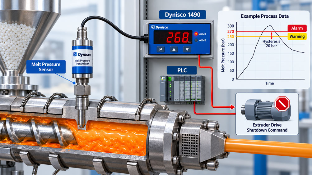
During plastic extrusion, the melt pressure upstream of a screen changer rises unusually sharply. Possible causes include a clogged screen, changes in melt viscosity or restricted material flow. If the pressure is not limited in time, the extruder, melt pipes and dies may be subjected to excessive loads.
A Dynisco melt pressure sensor measures the process pressure. A connected indicator or controller monitors the measured value and can trigger an alarm when a configured threshold is exceeded.
However, simply programming a pressure value is not enough to ensure reliable operation. Threshold, hysteresis, measurement dynamics, sensor faults and shutdown response must be coordinated.
For a normal process alarm, a warning signal to the machine controller may be sufficient. However, if a hazardous overpressure condition must be prevented, the complete protective function, including sensors, evaluation logic and shutdown elements, must be designed according to the risk assessment.
This article explains how Dynisco components can be used for melt pressure monitoring, how thresholds and hysteresis work, and why a latched shutdown is often preferable to automatic restart authorization.
Table of Contents
- Melt Pressure Monitoring on an Extruder
- Causes of a Dangerous Pressure Increase
- Structure of the Pressure Measurement and Alarm Chain
- Distinguishing Dynisco Indicators and Controllers
- Correctly Setting the Pressure Threshold
- Determining Hysteresis and Reset Point
- Warning, Shutdown and Restart Authorization
- Practical Example with Threshold and Response Time
- Selecting a Suitable Melt Pressure Sensor
- Correctly Connecting 4–20 mA and Strain Gauge Signals
- Checking Measuring Range and Scaling
- Response Time and Pressure Dynamics
- Sensor Faults and Cable Interruptions
- Relay Contacts and Switching States
- Mounting Hole and Sensor Installation
- Melt Temperature and Sensor Behavior
- Material Changes and Melt Viscosity
- Calibration and Functional Testing
- Safety-Related Shutdown
- Testing and Commissioning Procedure
- Typical Faults and Diagnostics
- Suitable Dynisco Products at ICS
- Conclusion
- Frequently Asked Questions
1. Melt Pressure Monitoring on an Extruder
A pressure sensor monitors the melt pressure, for example, upstream of the screen changer, before the die or in a suitable melt channel.
The signal is transmitted to a Dynisco indicator or a control system. Thresholds for process monitoring can then be evaluated.
The measurement task must distinguish between an operational warning, a control intervention and a required protective shutdown.
2. Causes of a Dangerous Pressure Increase
Melt pressure depends on screw speed, throughput, material properties, temperature and flow resistance, among other factors.
Typical causes of increased pressure include clogged screens, restricted flow channels, insufficient melt temperatures, unsuitable materials or excessive throughput.
Rising pressure should therefore not be addressed solely by acknowledging an alarm. Its cause must be investigated.
3. Structure of the Pressure Measurement and Alarm Chain
A typical monitoring system consists of the following components:
- Dynisco melt pressure sensor.
- Electrical signal transmission.
- Dynisco indicator or controller.
- Alarm relay or signal output.
- Machine control system.
- Suitable shutdown element.
For normal process monitoring, the alarm relay can transmit a signal to the PLC. Additional requirements apply to all components involved in a safety-related shutdown.
4. Distinguishing Dynisco Indicators and Controllers
The Dynisco 1490 is a universal indicator with up to two programmable alarms. It supports strain gauge, current and voltage signals, among others, as well as adjustable alarm hysteresis.
The Dynisco 1480 also provides alarm functions and can be used for suitable pressure measurement applications.
In contrast, the Dynisco 1496/1498 are primarily temperature controllers with PID control functions. They must not be considered equivalent replacements for a dedicated melt pressure alarm device without verification.
5. Correctly Setting the Pressure Threshold
A threshold must be derived from the permissible operating conditions and risk assessment.
Important influencing factors include:
- Maximum permissible pressure of the affected system components.
- Normal operating pressure and process fluctuations.
- Measurement uncertainty and dynamic sensor behavior.
- Response time until pressure is actually reduced.
- Possible pressure increase during this response time.
The shutdown threshold must be sufficiently below the relevant maximum permissible pressure. An arbitrary percentage margin relative to the sensor full-scale value is not a suitable general rule.
6. Determining Hysteresis and Reset Point
Hysteresis prevents an alarm from repeatedly switching on and off due to small fluctuations around the threshold.
For a high alarm with a threshold of 270 bar and a hysteresis of 20 bar, the alarm may, for example, become active at 270 bar and return to its normal state only when the pressure falls below the reset point of 250 bar.
The exact threshold logic and equality conditions must be verified according to the instrument configuration.
Important: Hysteresis does not automatically mean that a machine which has been shut down may restart.
7. Warning, Shutdown and Restart Authorization
A two-stage concept can first issue a warning and then request a shutdown if the pressure continues to rise.
For a latched shutdown, the shutdown state is retained. A return of the pressure below the hysteresis threshold does not automatically cause the machine to restart.
| State | Condition | Intended Response |
|---|---|---|
| Normal operation | Pressure below 250 bar | No pressure warning |
| Pre-warning | Pressure at or above 250 bar | Warning signal and investigation of the cause |
| Shutdown request | Pressure at or above 270 bar | Activate defined shutdown logic |
| Reset range | Pressure falls below 250 bar | Alarm condition reset; shutdown interlock remains active |
| Restart authorization | Pressure within the permissible range, fault corrected and approval granted | Acknowledgment and controlled restart according to the machine concept |
| Measurement fault | No valid pressure signal | Defined fault response, no automatic authorization |
All pressure values in the table are hypothetical. They do not represent recommended safety limits for any specific extruder.
8. Practical Example with Threshold and Response Time
A hypothetical extruder is equipped with a melt pressure transmitter with a measuring range of 0 to 350 bar and a 4–20 mA output.
The following values are assumed for the example:
- Relevant maximum permissible process pressure: 320 bar.
- Pre-warning: 250 bar.
- Shutdown threshold: 270 bar.
- Hysteresis: 20 bar.
- Assumed pressure rise rate: 30 bar/s.
- Total assumed response time until effective pressure limitation: 0,6 s.
8.1 Current Signal at the Shutdown Threshold
For an ideally linearly scaled pressure transmitter:
I = 4 mA + 16 mA · p / pEndwert
At the threshold of 270 bar:
I = 4 mA + 16 mA · 270 / 350
I ≈ 16,34 mA
8.2 Current Signal at the Reset Point
At 250 bar:
I = 4 mA + 16 mA · 250 / 350
I ≈ 15,43 mA
8.3 Pressure Increase During the Response
For the simplified model:
Δp = (dp/dt) · t
Δp = 30 bar/s · 0,6 s
Δp = 18 bar
The hypothetical pressure reached after this period is:
p = 270 bar + 18 bar
p = 288 bar
The calculated margin relative to the assumed maximum permissible pressure is:
320 – 288 = 32 bar
8.4 Summary of Results
| Parameter | Assumption or Calculation | Result |
|---|---|---|
| Sensor measuring range | Freely selected | 0 to 350 bar |
| Maximum permissible process pressure | Freely selected | 320 bar |
| Pre-warning | Freely selected | 250 bar |
| Shutdown threshold | Freely selected | 270 bar |
| Hysteresis | 270 – 250 | 20 bar |
| Current at 270 bar | 4 + 16 · 270 / 350 | 16,34 mA |
| Current at 250 bar | 4 + 16 · 250 / 350 | 15,43 mA |
| Pressure rise rate | Freely selected | 30 bar/s |
| Response time | Freely selected | 0,6 s |
| Additional pressure increase | 30 · 0,6 | 18 bar |
| Calculated pressure | 270 + 18 | 288 bar |
| Remaining pressure margin | 320 – 288 | 32 bar |
The calculation assumes a constant pressure rise rate. Actual pressure profiles may differ considerably. In particular, pressure may continue to increase after shutdown has been initiated.
Therefore, this example does not demonstrate that a protective function is adequate. Worst-case operating conditions, measurement deviations and actual response times must also be considered.
9. Selecting a Suitable Melt Pressure Sensor
The sensor must be suitable for the pressure range, melt temperature, medium, process connection and required measurement dynamics.
Dynisco offers strain gauge-based melt pressure sensors and melt pressure transmitters with amplified output signals, among other products.
A higher measuring range is not automatically better: The required accuracy at the alarm threshold must also be considered.
10. Correctly Connecting 4–20 mA and Strain Gauge Signals
Dynisco melt pressure sensors may have different electrical output signals.
A passive strain gauge transducer with an mV/V output requires suitable bridge excitation and signal evaluation. A 4–20 mA transmitter operates according to its two-wire or other specified connection configuration.
The Dynisco 1490 supports both signal types in suitable configurations. Input type, wiring and, where necessary, transmitter power supply must match the actual instrument configuration.
11. Checking Measuring Range and Scaling
The indicator or controller must use the sensor’s actual configured measuring range.
For example, if a sensor is configured for 0 to 350 bar but the controller is scaled for 0 to 500 bar, incorrect pressure values and consequently incorrect alarm activation points will result.
Whenever the sensor, measuring span or input signal changes, the scaling must be checked before production is released.
12. Response Time and Pressure Dynamics
The total response time consists of pressure transmission to the sensor, its dynamic behavior, signal processing, alarm evaluation and operation of the shutdown device.
Digital filters and alarm delays can suppress brief pressure peaks. This may be desirable for process indication but problematic when overpressure shutdown is required.
The maximum possible pressure increase before the protective response becomes effective must be considered.
13. Sensor Faults and Cable Interruptions
A defective sensor must not simply be interpreted as low process pressure.
Possible conditions to consider include cable breakage, power supply failure, overrange and invalid input signals.
The Dynisco 1490 has sensor break detection functions depending on the input type. The respective alarm behavior must be verified based on the configured input type and instrument configuration.
Particularly with zero-based signals, reliable fault detection must not be assumed without verification.
14. Relay Contacts and Switching States
When connecting an alarm relay, the normally energized principle, contact configuration and switching capacity must be considered.
A normally energized configuration designed for this purpose can, for example, trigger a shutdown request if the controller loses its power supply. However, this does not automatically detect every possible sensor or relay fault.
The alarm contacts of an indicating instrument are not necessarily suitable for directly interrupting high motor currents. Suitable switching or safety devices must be controlled according to the machine concept.
15. Mounting Hole and Sensor Installation
A technically correct controller cannot compensate for a mechanically incorrectly installed sensor.
The mounting hole must match the sensor type. With typical Dynisco connections using 1/2-20 UNF threads, the thread, clearance for the sensor tip and the intended sealing surface are particularly important.
Solidified plastic residues or a damaged seating surface can impair the diaphragm and measurement behavior. Cleaning and inspection must be performed using suitable tools according to the manufacturer’s instructions.
16. Melt Temperature and Sensor Behavior
Melt temperature influences viscosity and therefore frequently affects process pressure.
Temperature changes can also affect the sensor zero point. The permissible temperatures at the diaphragm, sensor stem and electronics housing must be considered separately according to the instrument configuration.
A melt pressure alarm must therefore not be defined solely on the basis of a single measurement taken under different temperature conditions.
17. Material Changes and Melt Viscosity
Different plastics, fillers and formulations can produce different pressure profiles at identical screw speeds.
Different product settings or operating windows may therefore be necessary. However, alarm thresholds may only be changed within the verified permissible system limits.
A material change is not a reason to disable required overpressure protection.
18. Calibration and Functional Testing
Suitable testing includes the sensor indication, scaling, alarm outputs and the intended response of the machine control system.
An electrical shunt test or R-Cal function can be used to check parts of the measurement chain with suitable Dynisco sensors. However, it does not replace a complete pressure calibration using an appropriate pressure reference.
Where shutdown functions are required, the actual operation of the complete functional chain must also be demonstrated according to the approved test procedure.
19. Safety-Related Shutdown
A conventional process alarm is not automatically a safety-related shutdown.
If overpressure can create a hazard for personnel or machinery, the required safety function must be derived from the risk assessment.
The requirements of EN ISO 13849-1 or IEC 62061, among others, may be relevant.
A sensor with SIL- or PL-related characteristics does not automatically make a conventional Dynisco indicator and its relay output a correspondingly certified safety chain.
The sensor, logic, shutdown element, diagnostics and required testing must be evaluated as a complete system.
20. Testing and Commissioning Procedure
The following procedure is recommended for traceable commissioning:
- Define the maximum permissible process pressure.
- Check the sensor measuring range and measurement uncertainty.
- Inspect the mounting hole and sensor connection.
- Verify the electrical signal and scaling.
- Configure warning and shutdown thresholds.
- Set hysteresis and, where applicable, alarm latching.
- Check relay states and fault responses.
- Test response time and shutdown behavior.
- Verify acknowledgment and restart operation.
- Document test results and configuration.
Testing must be performed under suitable safe conditions and according to the applicable machine testing instructions.
21. Typical Faults and Diagnostics
If the alarm function does not respond as expected, the signal path, scaling, thresholds and fault status should be investigated first.
An alarm that repeatedly switches on and off may indicate insufficient hysteresis, significant pressure fluctuations or unstable measured values.
A delayed shutdown may result from unsuitable filters, extended signal processing, delays in the control system or an unfavorably positioned pressure measuring point.
A consistently high or low measured value may also result from sensor damage, temperature drift or incorrect parameterization.
22. Suitable Dynisco Products at ICS
ICS Schneider Messtechnik offers suitable Dynisco components for melt pressure measurement, process indication and alarming.
| Product | Main Function | Important Selection Consideration |
|---|---|---|
| Dynisco 1490 | Universal process indicator with up to two alarms, adjustable hysteresis and optional communication | Check output and relay configuration |
| Dynisco 1480 | Process indicator with two standard alarms and an optional third alarm | Select the required alarm configuration and signal input |
| Dynisco SPX 4222 | Melt pressure transmitter with 4–20 mA, optional HART and ATEX version | Specify measuring range, process connection and approval |
| Dynisco PT418/PT419 | Oil-filled melt pressure sensor with strain gauge output for suitable applications | Strain gauge input and bridge excitation required |
| Dynisco 1496/1498 | Temperature controller with PID and alarm functions | Primarily for temperature control; not a universal alternative to a pressure controller |
Dynisco 1490: This model is particularly suitable for consideration in conventional melt pressure indication with adjustable high/low alarms. Different input and relay configurations are available. Alarm hysteresis and suitable alarm latching can be used depending on the configuration.
Dynisco 1490 – Product Information
Dynisco SPX 4222: This intelligent melt pressure transmitter has a 4–20 mA output and is optionally available with HART. Suitable variants are also available with corresponding explosion protection approvals.
Dynisco SPX 4222 – Product Information
When selecting components, the pressure range, material, melt temperature, signal type, alarm functions and required protective function should be known.
Additional Dynisco Products at ICS Schneider Messtechnik
23. Conclusion
A reliable melt pressure alarm requires proper coordination between the sensor, measurement signal, threshold, hysteresis and machine response.
Hysteresis prevents unnecessary alarm switching. A latched shutdown can prevent the machine from restarting automatically after a temporary pressure decrease.
The response time until pressure is actually limited and a defined response to sensor and signal faults are particularly important.
Dynisco indicators and controllers such as the 1490 can provide suitable alarm functions for operational pressure monitoring.
However, a safety-related overpressure shutdown must be designed, evaluated and tested as a complete safety function. A single alarm relay does not replace such verification.
24. Frequently Asked Questions
24.1 Which Dynisco Controller Is Suitable for a Melt Pressure Alarm?
The Dynisco 1490 is a possible solution for process indication and threshold monitoring. It has up to two programmable alarms. Its exact suitability depends on the sensor, output configuration and protective requirements.
24.2 What Is a High Alarm?
A high alarm is activated when the measured value reaches or exceeds the configured upper threshold. The exact switching condition depends on the instrument configuration.
24.3 Why Does a Melt Pressure Alarm Need Hysteresis?
Hysteresis prevents frequent switching when the pressure fluctuates around the threshold. The alarm activation point and reset point are therefore separated.
24.4 How Is the Reset Point Calculated?
For a high alarm, the reset point can be determined, for example, by subtracting the hysteresis from the alarm threshold. At 270 bar with 20 bar hysteresis, the result is 250 bar.
24.5 May the Extruder Restart Automatically After the Pressure Drops?
This depends on the machine and protection concept. With a latched shutdown, the machine remains switched off until the intended restart authorization is granted, even if the pressure decreases.
24.6 How Is the Correct Pressure Threshold Determined?
The threshold is derived from the permissible system pressure, operating behavior, measurement uncertainty and required response time. There is no universally applicable value.
24.7 What Role Does Melt Temperature Play?
It influences viscosity and therefore process pressure. Temperature changes can also affect the sensor’s measurement deviation.
24.8 Can a Strain Gauge Sensor Be Connected Directly to the Dynisco 1490?
The Dynisco 1490 supports suitable strain gauge inputs. The specific bridge circuit, excitation, sensitivity and instrument configuration must be compatible.
24.9 Can a 4–20 mA Transmitter Be Used?
Yes, provided the indicator or controller is configured for the corresponding current input and the power supply and scaling are correctly designed.
24.10 What Happens If a Cable Is Disconnected?
The behavior depends on the signal type, instrument and parameterization. Cable interruption must be considered in the fault response and tested accordingly.
24.11 Is an Alarm Relay Sufficient for a Safe Shutdown?
Not automatically. A safety-related shutdown requires evaluation of the complete function, including sensor, logic and shutdown element.
24.12 Why Does the Alarm Repeatedly Switch On and Off?
Possible causes include insufficient hysteresis, significant pressure fluctuations, interference in the measurement signal or unsuitable filter settings.
24.13 Can an Incorrect Mounting Hole Affect the Alarm?
Yes. A damaged or incorrectly positioned sensor diaphragm can impair measurement behavior. The mounting hole geometry and installation must therefore be checked.
24.14 What Is R-Cal on Dynisco Sensors?
R-Cal refers to an electrical shunt test function available on suitable sensors. It can be used to check the signal path but does not replace a complete pressure calibration.
24.15 Must the Complete Shutdown Chain Be Tested?
If pressure shutdown is intended as a protective function, its operation through to the required safe machine response must be verified according to the specified test procedure.
24.16 Can the Dynisco 1490 Also Measure Temperature?
Yes. In addition to pressure signals, the universal input concept supports thermocouples and suitable resistance thermometers, among others.
24.17 Are the Dynisco 1496 and 1498 Pressure Controllers?
These instruments are primarily intended for temperature control. They provide PID and alarm functions. Their use for other tasks must be verified against the specific input configuration and requirements.
24.18 What Information Does ICS Need for Product Selection?
The required information includes sensor and signal type, measuring range, process pressure, melt temperature, desired alarm thresholds, relay functions and whether a normal process warning or a safety-related shutdown is required.