


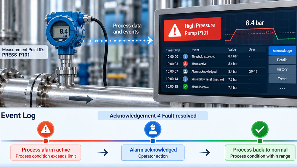
In an industrial plant, an IIoT system monitors the pressure of a pump. When the process pressure exceeds the configured limit, an alarm message appears on the dashboard.
An operator notices the message and acknowledges it. The alarm then disappears from the list of unacknowledged messages. However, the pressure is still above the permissible limit.
During a subsequent evaluation, a problem becomes apparent: The event log only contains the entry “Alarm acknowledged”. It is no longer possible to determine exactly when the fault occurred or when the pressure returned to normal.
Alarm acknowledgement is an operator action. It does not automatically confirm that the cause of the process fault has been eliminated.
For traceable IIoT and SCADA systems, process events, alarm states and operator actions must therefore be recorded separately.
This article explains the required states, timestamps and data structures. A practical example demonstrates how to create a complete alarm history and evaluate it correctly.
Table of Contents
- Alarm Management and Event Documentation
- Process Events, Alarms and Acknowledgement
- Modeling Alarm States Separately
- What Alarm Acknowledgement Actually Means
- Structure of an Event Log
- Event IDs and Measurement Point IDs
- Timestamps and Time Sources
- Practical Example: Alarm Duration and Acknowledgement Time
- Return to Normal Conditions
- Repeated and Overlapping Alarms
- User Identification and Permissions
- Local Alarm Processing at the Edge
- MQTT, OPC UA and Data Transmission
- Buffering During Communication Failures
- Data Quality and Duplicate Events
- Historian and Long-Term Storage
- Alarm Display and Event List
- Alarm Management and ISA-18.2
- IT/OT Security and Audit Trails
- Testing and Commissioning Procedure
- Typical Errors and Troubleshooting
- Suitable ICS Products and IIoT Solutions
- Conclusion
- Frequently Asked Questions
1. Alarm Management and Event Documentation
In industrial plants, pressure, temperature, level and other process variables are continuously monitored.
When a defined condition is met, the control system or an IIoT application can trigger an alarm.
A current alarm display is not sufficient for subsequent evaluation. It must also remain possible to determine when the condition occurred, when it ended and which operator actions were performed.
2. Process Events, Alarms and Acknowledgement
A process event describes an observed change in state, such as a pressure limit being exceeded.
An alarm is a correspondingly configured notification that requires operator attention or action.
Acknowledgement confirms that the relevant message has been noticed. It does not automatically confirm that the fault has been corrected or a verification has been successfully completed.
3. Modeling Alarm States Separately
An important requirement is the separate storage of alarm activity and acknowledgement status.
The OPC UA information model for Alarms & Conditions uses the states ActiveState and AckedState, among others, for this purpose.
| Alarm Active | Acknowledged | Meaning |
|---|---|---|
| No | Yes | Normal condition; no acknowledgement pending |
| Yes | No | Process alarm active and not yet acknowledged |
| Yes | Yes | Process alarm still active but acknowledged |
| No | No | Process has returned to normal; acknowledgement of a previous alarm state is still pending, provided the system supports this state |
The exact state sequence depends on the implemented alarm model. Not every system supports all combinations or subsequent acknowledgement of inactive alarms.
4. What Alarm Acknowledgement Actually Means
An acknowledgement documents an operator action associated with a specific alarm message.
It should reference at least the affected alarm, the time and the responsible user.
The process condition must continue to be monitored independently.
An active alarm must not be considered resolved simply because an operator has acknowledged the message.
5. Structure of an Event Log
An event log stores individual state changes as records that can be assigned to specific points in time.
Typical event types include alarm activation, alarm acknowledgement, return to normal conditions and, where applicable, additional operator confirmation.
The individual records should be retained even if the current alarm status changes later.
A historical alarm activation must therefore not be overwritten by a subsequent acknowledgement.
6. Event IDs and Measurement Point IDs
Different identifiers are useful for unambiguous assignment.
The measurement point ID identifies the physical monitoring point, for example PRESS-P101.
An alarm definition identifies the monitored condition, such as HIGH-PRESSURE. An alarm instance ID links the state changes belonging to the same alarm occurrence.
In addition, each individual log entry receives a unique event ID.
This allows multiple acknowledgements, alarm activations and status changes to be linked in a traceable manner without losing their chronological order.
7. Timestamps and Time Sources
Every event requires a traceable time reference.
It is particularly important to distinguish between the time when an event originates and the time when it is received by the central system.
These timestamps may differ due to network delays.
The participating devices should therefore be synchronized using suitable methods such as NTP or, where higher requirements apply, PTP.
Unambiguous UTC timestamps with sufficient resolution are useful for storage. The local plant time can additionally be displayed in the user interface.
8. Practical Example: Alarm Duration and Acknowledgement Time
A pump is monitored using a pressure transmitter. The system generates a high-pressure alarm when the pressure exceeds a defined threshold for at least three seconds.
The alarm is acknowledged through the operator panel. The return to normal conditions is logged independently.
8.1 Initial Data
- Measurement point ID: PRESS-P101.
- Alarm threshold: 8.0 bar.
- Reset threshold: 7.5 bar.
- Activation delay: 3 seconds.
- Reset delay: 1 second.
- Alarm acknowledgement by user OP-17.
- All times refer to the same synchronized plant time.
The following values are freely selected example assumptions and do not represent instrument-specific limits.
8.2 Recording Events Chronologically
| Time | Event | Alarm Status | Acknowledgement |
|---|---|---|---|
| 10:00:00 | Pressure exceeds 8.0 bar | Activation pending | – |
| 10:00:03 | Alarm becomes active | Active | Pending |
| 10:00:07 | User OP-17 acknowledges the alarm | Still active | Acknowledged |
| 10:00:14 | Pressure falls below 7.5 bar | Reset pending | Acknowledged |
| 10:00:15 | Alarm becomes inactive | Inactive | Acknowledged |
8.3 Calculating Acknowledgement Time
The alarm becomes active at 10:00:03 and is acknowledged at 10:00:07.
tAcknowledgement = 7 s – 3 s = 4 s
The operator therefore responds four seconds after the recorded alarm activation.
8.4 Calculating Alarm Duration
The alarm remains active from 10:00:03 until 10:00:15.
tAlarm = 15 s – 3 s = 12 s
The active alarm duration is twelve seconds.
8.5 Evaluating Process Duration Separately
The observed threshold exceedance begins at 10:00:00. The reset criterion is reached at 10:00:14.
The period between these two process events is 14 seconds.
Due to hysteresis and delays, this does not automatically correspond to the time during which the pressure was actually above 8.0 bar.
8.6 Interpreting the Results
The acknowledgement after four seconds confirms an operator action while the pressure is still too high.
The alarm only ends once the specified reset criterion has been fulfilled.
If the system stored the acknowledgement as the end of the alarm, the documented alarm duration would incorrectly be shortened by eight seconds.
For reliable evaluation, alarm activation, operator action and process normalization must therefore be retained separately.
9. Return to Normal Conditions
An alarm may only be evaluated as inactive according to the specified reset logic.
For a high-pressure alarm, hysteresis can prevent the status from continuously switching due to small pressure fluctuations.
An additional reset delay ensures that the process remains within the specified range for a sufficient period.
Acknowledgement does not change these conditions.
10. Repeated and Overlapping Alarms
A measurement point can switch repeatedly between alarm and normal states within a short period.
In suitable systems, each new alarm occurrence receives its own identifier.
This prevents an acknowledgement from accidentally being applied to an alarm that is triggered again later.
OPC UA Alarms & Conditions can also manage older, still unacknowledged states separately for this purpose.
11. User Identification and Permissions
A traceable acknowledgement should be associated with an authenticated user.
Shared user accounts make it difficult to determine later who acknowledged a message.
A role-based permission concept can distinguish between viewing, acknowledging, configuring and making administrative changes.
Critical alarms may require additional confirmations or explanations.
12. Local Alarm Processing at the Edge
In IIoT architectures, measured values can initially be acquired and processed by an edge gateway.
Local alarm evaluation enables configured process conditions to be detected independently of the cloud dashboard.
The edge system should clearly record event times, measurement point IDs and state changes.
However, a local alarm function is not automatically a safety-related protective function.
13. MQTT, OPC UA and Data Transmission
OPC UA Alarms & Conditions provides a standardized state and acknowledgement model.
With MQTT, however, the required event fields and acknowledgement procedures must be defined within the application or the data model being used.
Each message should contain a unique identifier and a timestamp indicating when the event originated.
Simply transmitting the current Boolean alarm status is not sufficient for a complete alarm history.
14. Buffering During Communication Failures
During a network connection failure, process alarms may continue to occur locally.
Suitable edge systems therefore temporarily store events in a persistent buffer.
When the connection is restored, the stored events are transmitted with their original timestamps.
Important requirements include sufficient storage capacity, restart behavior and reliable transmission without data loss.
15. Data Quality and Duplicate Events
During retransmission, events may arrive more than once in the central system.
A unique event ID makes it possible to identify such duplicates.
Invalid measured values, communication failures and implausible timestamps must also be marked accordingly.
A measured value with an invalid quality status must not be interpreted as a normal process condition without verification.
16. Historian and Long-Term Storage
A historian stores time-related process data for subsequent analysis.
For alarm history, state transitions and associated operator actions must be available in addition to measured values.
A well-structured architecture can logically separate the measurement archive, event log and audit trail while linking them through stable identifiers.
This allows the pressure profile, alarm duration and operator response to be evaluated together later.
17. Alarm Display and Event List
A current alarm display answers the question of which messages presently require attention.
The event list, on the other hand, documents which changes occurred in the past.
Both views should be clearly distinguishable.
An acknowledged alarm that remains active must continue to be recognizable as an existing process condition according to the selected display and alarm concept.
18. Alarm Management and ISA-18.2
The ISA-18.2 standard series and the international IEC 62682 standard address the management of industrial alarm systems.
Topics include alarm philosophy, priorities, operator responses, testing, monitoring and documentation.
A complete event history supports the evaluation of alarm frequency, response times and recurring faults.
Which requirements are mandatory depends on the plant type, applicable standards and operator specifications.
19. IT/OT Security and Audit Trails
An audit trail documents relevant changes and operator actions, including user identification and timestamps.
Acknowledgements and changes to alarm thresholds should be traceable and protected against unauthorized manipulation.
Suitable user permissions, secure communication and controlled access to historical data are important for this purpose.
Retention periods and requirements for tamper resistance must be defined according to the specific application.
20. Testing and Commissioning Procedure
The following procedure is recommended for setting up a traceable alarm history:
- Define the measurement point, alarm condition and reset criterion.
- Model activation and acknowledgement states separately.
- Define unique alarm instance IDs and event IDs.
- Synchronize time sources and timestamps.
- Configure user roles and acknowledgement permissions.
- Test alarm activation and return to normal conditions.
- Verify acknowledgement while the alarm remains active.
- Simulate communication failure and subsequent event transmission.
- Check duplicate detection and historian entries.
- Document results and configuration.
21. Typical Errors and Troubleshooting
Alarm disappears completely after acknowledgement: Check whether the display and state model incorrectly combine alarm activity and acknowledgement status.
Alarm duration is calculated too short: The acknowledgement timestamp may have been used as the alarm end time.
Events appear in the wrong order: Check time sources, time zones and reception timestamps.
Events are missing after a network failure: Check persistent buffering and retransmission.
Acknowledgement appears multiple times: Verify event IDs and duplicate detection.
User cannot be identified: Check authentication, role management and the audit log.
22. Suitable ICS Products and IIoT Solutions
ICS Schneider Messtechnik offers IIoT solutions for connecting industrial sensors, transmitters and control systems.
The specific separation of alarm state, acknowledgement and event history must be implemented or verified in the edge, SCADA or cloud system used.
| Product / Solution | Important Features | Contribution to Alarm Architecture |
|---|---|---|
| ICS IIoT Solutions | Edge gateways, MQTT/HTTPS, OPC UA, data modeling | Integration of process data and alarm events |
| Siemens SITRANS P320 | Pressure and differential pressure measurement, HART, NE107 diagnostics | Measurement and diagnostic data source for alarm evaluation |
| WIKA NETRIS®2 | LoRaWAN, two intrinsically safe 4–20 mA inputs | Wireless transmission of suitable measured values |
| WIKA NETRIS®3 | LoRaWAN transmission from compatible digital WIKA instruments | Wireless data integration for condition monitoring |
22.1 ICS IIoT Solutions
The IIoT solutions from ICS Schneider Messtechnik connect industrial measuring instruments to edge gateways and higher-level systems through suitable interfaces.
Depending on the project, supported integration methods include RS-485/Modbus RTU, HART, IO-Link, OPC UA, Ethernet, MQTT and HTTPS.
ICS provides support with instrument selection, data models, register mapping, transmission and commissioning.
Requirements for alarm acknowledgement, historical logging and audit trails are defined within the specific integration project.
ICS IIoT Solutions – Product Overview
22.2 Siemens SITRANS P320 – Process Transmitter
The Siemens SITRANS P320 is a digital process transmitter for measuring gauge pressure, absolute pressure, differential pressure and other derived process variables.
It provides HART communication and comprehensive diagnostic functions according to NAMUR NE107.
In an IIoT alarm architecture, the transmitter can provide measured values and instrument status information. Higher-level acknowledgement and event logging are implemented in the corresponding evaluation system.
Siemens SITRANS P320 – Product Information
22.3 WIKA NETRIS®2 – LoRaWAN Radio Unit
The WIKA NETRIS®2 transmits measured values via LoRaWAN and features two intrinsically safe analog inputs with 4–20 mA.
It is suitable for wireless integration of compatible transmitters into IIoT systems, including appropriately approved hazardous areas.
Due to transmission intervals and wireless communication latency, suitability for time-critical alarms must be carefully evaluated.
A complete OPC UA alarm acknowledgement model cannot be inferred from the measurement transmission function alone.
WIKA NETRIS®2 – Product Information
22.4 WIKA NETRIS®3 – LoRaWAN Radio Unit
The WIKA NETRIS®3 is a radio unit for connecting suitable digital WIKA measuring instruments.
It transmits measurement data via LoRaWAN and is designed for corresponding industrial remote monitoring applications.
The radio unit supports the provision of measurement data to a higher-level IIoT application. Alarm processing, acknowledgement and long-term event storage must be implemented appropriately in that system.
WIKA NETRIS®3 – Product Information
Additional IIoT Solutions at ICS Schneider Messtechnik
23. Conclusion
Alarm acknowledgement and the end of a process fault are two different events.
Combining these states can result in incomplete alarm histories, incorrect alarm durations and operator actions that cannot be traced.
A well-structured IIoT architecture requires separate state variables, unique event IDs and synchronized timestamps.
Communication failures, buffering, user permissions and data quality must also be considered.
The most important rule is: Document process events, log operator actions separately and link both sets of information in a traceable manner using unique identifiers.
24. Frequently Asked Questions
24.1 What Is Alarm Acknowledgement?
An operator action confirming that a user has noticed a specific alarm message.
24.2 Does Acknowledgement End a Process Alarm?
No. The process alarm remains active according to its activation and reset conditions.
24.3 What Is the Difference Between an Alarm and an Event?
An event documents a change in state. An alarm is a notification that requires a response according to the alarm concept.
24.4 What Information Must an Event Log Contain?
At least the event type, unique identifier, affected measurement point, timestamp and relevant state information required for evaluation.
24.5 Why Does Every Log Entry Need an Event ID?
So that individual events can be uniquely identified, transmitted and distinguished from duplicates when necessary.
24.6 What Is an Alarm Instance ID?
An identifier linking related state changes belonging to the same alarm occurrence.
24.7 Why Must the User Be Recorded During Acknowledgement?
So that it can later be determined who performed the corresponding operator action.
24.8 What Does ActiveState Mean in OPC UA?
It describes the activity state of the corresponding alarm condition.
24.9 What Does AckedState Mean in OPC UA?
It indicates whether the relevant state requiring acknowledgement has already been acknowledged.
24.10 Can Alarms Remain Unacknowledged After Returning to Normal?
Yes. Appropriately configured alarm models can retain previous, now inactive states for subsequent acknowledgement.
24.11 Which Timestamps Are Important for Alarm History?
In particular, event occurrence, acknowledgement, return to normal conditions and, where applicable, the reception time in the central system.
24.12 Why Should Time Sources Be Synchronized?
So that events from different devices can be correctly assigned and evaluated chronologically.
24.13 Can MQTT Transmit Alarm Acknowledgements?
Yes, provided suitable message formats, permissions and corresponding acknowledgement logic are implemented.
24.14 Are OPC UA and MQTT Equivalent for Alarm Management?
No. OPC UA Alarms & Conditions provides a standardized information model. With MQTT, the required alarm semantics are defined for the specific application.
24.15 What Happens During a Network Failure?
With a suitable architecture, events can be buffered locally and transmitted after the connection has been restored.
24.16 Must an Acknowledged Alarm Remain Visible?
As long as the alarm condition remains active, it must remain recognizable according to the established alarm and operator interface concept.
24.17 Is an IIoT Alarm Function Automatically Safety-Related?
No. Safety-related functions require a separate assessment and a suitable technical implementation.
24.18 What Information Does ICS Need for an IIoT Quotation?
The required information includes the number and type of measurement points, existing interfaces, alarm conditions, acknowledgement procedures, required time resolution, network architecture, retention periods, user roles and event documentation requirements.