


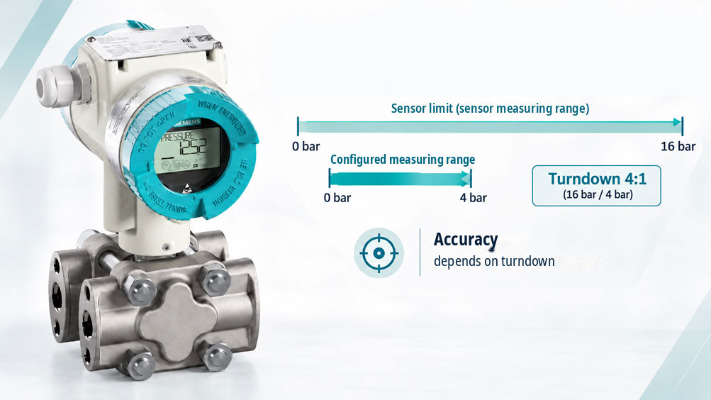
The Siemens SITRANS P320 is a digital process pressure transmitter whose measuring span can be adapted to different applications. This flexibility is particularly useful for plant engineering, commissioning and device replacement. However, the term turndown is frequently misunderstood: A smaller configured measuring span does not automatically mean that the sensor cell maintains its original percentage accuracy unchanged at that setting.
The key is to distinguish between the physical measuring range of the sensor cell, the configured lower and upper range values, the turndown ratio and the associated measurement deviation. These parameters determine whether the pressure transmitter is suitable for the respective process application.
This technical article explains these relationships using the SITRANS P320 with a 4–20 mA/HART output, describes the manufacturer-specific accuracy specifications and shows how plant engineers and operators can select a suitable sensor cell and configure it correctly.
Table of Contents
1. Why Turndown Is Important for Pressure Transmitters
In industrial plants, the maximum sensor range and the process measuring span actually required often differ. For example, a pressure transmitter may have a sensor cell rated for 16 bar, while the application only requires a range from 0 to 4 bar.
Configuration allows the output signal to be scaled to the desired process range. With the SITRANS P320, the lower and upper range values can be configured within the permissible device limits.
The advantage is flexible adaptation to different plant conditions. However, the user must verify that the desired measuring span is within the permissible sensor limits and determine the specified measurement deviation for the selected configuration.
Turndown is therefore not an independent quality characteristic, but describes the ratio between the available and configured measuring span.
2. Measuring Principle and Device Versions of the SITRANS P320
The Siemens SITRANS P320 is a digital pressure transmitter for demanding process applications. Depending on the version, it is suitable for measuring gauge pressure, absolute pressure, differential pressure and derived process variables such as level or flow.
The device electronically processes the signal from its pressure sensor cell and, in the HART version considered here, provides a configurable 4–20 mA signal as well as digital information.
The available sensor cells differ in nominal pressure range, permissible measuring span, pressure resistance and accuracy. Process connections, diaphragm seals, wetted materials and approvals also vary.
The product family should therefore not be considered a single universal pressure sensor. The specific order configuration and sensor cell version are always decisive for technical selection.
3. Distinguishing Sensor Limits, Lower Range Value and Upper Range Value
Several parameters must be distinguished to configure the measuring range correctly.
The lower and upper sensor limits describe the physically specified measuring range of the installed sensor cell. These measuring limits must not be confused with the mechanical overload limit.
The configured lower range value (LRV) corresponds to the lower value of the configured range, normally assigned to 4 mA in a standard linear 4–20 mA configuration.
The configured upper range value (URV) corresponds to the upper value of the configured range and therefore normally to 20 mA.
The difference between the upper and lower range values is the configured measuring span.
| Term | Meaning | Example |
|---|---|---|
| Nominal measuring range of the sensor cell | Sensor range specified by the manufacturer | 0 to 16 bar |
| Lower range value | Configured lower measuring range value | 0 bar |
| Upper range value | Configured upper measuring range value | 4 bar |
| Configured measuring span | Difference between upper and lower range values | 4 bar |
| Turndown | Maximum measuring span divided by configured measuring span | 4:1 |
| Overload limit | Permissible mechanical pressure load according to manufacturer specifications | Device-dependent |
This distinction prevents a simple scaling change from being incorrectly interpreted as an extension of the sensor’s physical capabilities.
4. Calculating Turndown and Measuring Span Ratio
The measuring span ratio of the SITRANS P320 is represented by the letter r.
r = maximum measuring span / configured measuring span
For a maximum measuring span of 16 bar and a configured measuring span of 4 bar, the calculation is:
r = 16 bar / 4 bar = 4
The resulting turndown is therefore 4:1.
If the same sensor cell is configured for a measuring span of 1 bar, the turndown is 16:1.
A higher turndown therefore means that a smaller portion of the available measuring span is used for output signal assignment.
However, the maximum permissible turndown depends on the selected SITRANS P320 sensor cell. Manufacturer specifications of up to 100:1 do not apply without restriction to every version.
5. Configured Measuring Span and 4–20 mA Output
With linear scaling, the configured pressure range is mapped to the analog output signal from 4 to 20 mA.
For a measuring range from 0 to 4 bar, the following equation applies:
I = 4 mA + (p / 4 bar) × 16 mA
At 2 bar, the output current is therefore 12 mA.
If the upper range value is configured to 1 bar, a pressure of 0.5 bar also corresponds to an output current of 12 mA.
This changes the current resolution in relation to the configured pressure span. However, the physical characteristics of the sensor cell remain unchanged.
The PLC must use the same lower and upper range values as the transmitter. Otherwise, incorrect pressure readings will result even if the sensor itself is operating correctly.
6. Understanding SITRANS P320 Accuracy Specifications
The accuracy of the SITRANS P320 must not be evaluated solely on the basis of a single percentage value.
For different sensor cells, Siemens specifies characteristic deviation, including hysteresis and repeatability, under defined reference conditions. The permissible deviation sometimes depends directly on the measuring span ratio r.
For example, the following applies to certain gauge pressure sensor cells in the pressure series with nominal measuring ranges of 1, 4, 16, 63 and 160 bar:
For r ≤ 5: Characteristic deviation ≤ 0.065% of the configured measuring span.
For a measuring span ratio of 5 < r ≤ 100, the following applies to these versions:
Characteristic deviation ≤ (0.004 × r + 0.045)% of the configured measuring span.
These formulas must not be applied universally to all SITRANS P320 versions. Different specifications may apply to sensor cells with nominal ranges of 250 mbar, 400 bar or 700 bar, as well as to other pressure versions.
The stated values refer to the specified characteristic deviation under reference conditions and must not be equated with the complete measurement uncertainty under actual operating conditions.
7. Influence of High Turndown on Measurement Deviation
As turndown increases, the percentage limit of the permissible characteristic deviation may also increase.
However, the evaluation must distinguish between the percentage value relative to the configured measuring span and the resulting absolute pressure deviation.
A smaller measuring span may result in a lower absolute error limit despite a higher percentage deviation.
For practical applications, it is also important to determine how large the absolute measurement deviation is in relation to the actual measured process pressure.
Additional influences from ambient temperature, mounting position, long-term behavior and calibration conditions may become particularly relevant at low process pressures.
High turndown is therefore not inherently disadvantageous. However, it must be evaluated on the basis of the actual error limits and the requirements of the measurement task.
8. Practical Example with a 16 bar Sensor Cell
8.1 Initial Data
A SITRANS P320 with a gauge pressure sensor cell from the pressure series and a nominal measuring range of 0 to 16 bar is to be used with different process measuring spans.
Two configurations are considered:
Version A: 0 to 4 bar.
Version B: 0 to 1 bar.
The example uses the Siemens specification for this sensor cell family under the stated reference conditions.
8.2 Calculation Basis
The measuring span ratio is calculated as follows:
r = 16 bar / configured measuring span
For r ≤ 5, the maximum characteristic deviation is specified as 0.065% of the configured measuring span.
For 5 < r ≤ 100, the following formula applies:
f(r) = (0.004 × r + 0.045)%
8.3 Calculation for Version A
With a configuration from 0 to 4 bar, the result is:
r = 16 / 4 = 4
Therefore, the limit of 0.065% of the configured measuring span applies.
Maximum characteristic deviation = 4 bar × 0.00065 = 0.0026 bar
This corresponds to 2.6 mbar.
8.4 Calculation for Version B
With a configuration from 0 to 1 bar, the turndown is:
r = 16 / 1 = 16
The percentage limit is calculated as follows:
f(16) = (0.004 × 16 + 0.045)% = 0.109%
The resulting absolute characteristic deviation is:
1 bar × 0.00109 = 0.00109 bar = 1.09 mbar
8.5 Additional Evaluation
Although the percentage characteristic deviation increases from 0.065% to 0.109%, the calculated absolute limit is lower for the smaller measuring span.
At an actual process pressure of 0.5 bar, however, 1.09 mbar corresponds to approximately 0.218% of this measured value.
The percentage deviation relative to the process measured value can therefore differ significantly from the percentage specified relative to the configured measuring span.
8.6 Summary of Results
| Parameter | Version A | Version B |
|---|---|---|
| Nominal measuring range | 0 to 16 bar | 0 to 16 bar |
| Configured measuring range | 0 to 4 bar | 0 to 1 bar |
| Turndown | 4:1 | 16:1 |
| Characteristic deviation | ≤ 0.065% | ≤ 0.109% |
| Absolute limit | 2.60 mbar | 1.09 mbar |
| Output at 50% of span | 12 mA at 2 bar | 12 mA at 0.5 bar |
8.7 Interpreting the Results
The example demonstrates why a general statement such as “higher turndown automatically means greater absolute measurement deviation” is incorrect.
When selecting a transmitter, the permissible characteristic deviation and additional error contributions under actual operating conditions must be taken into account.
Temperature deviations, installation influences, long-term stability and additional measurement point components must be evaluated separately.
The calculated values do not represent a complete uncertainty budget or automatically permissible process deviations.
9. Selecting the Appropriate Sensor Cell
Selection should be based on the normal process pressure, the required measuring span and possible pressure peaks.
For a process range from 0 to 1 bar, a sensor cell with a nominal measuring range of 16 bar is not necessarily required. A smaller suitable sensor cell may allow a lower turndown.
On the other hand, start-up conditions, pressure surges and mechanical loads must also be considered. Selecting a device solely on the basis of the smallest available measuring span may result in an unsuitable configuration.
Before ordering, the measuring limits, permissible overload, process conditions and required accuracy should therefore be verified.
Pressure type, material, sealing, housing, connection and required approvals also influence the selection.
10. Configuring the Measuring Range Locally and via HART
The SITRANS P320 with 4–20 mA/HART can be configured using the local operating buttons or via HART communication.
Suitable engineering tools, including SIMATIC PDM, are available for configuration.
Important settings include the lower range value, upper range value, unit, damping and the characteristic function required for the respective measurement task.
After making changes, it must be verified that the scaling in the PLC, process control system and visualization matches the transmitter settings.
For protected configurations, protective functions or SIL applications, additional access permissions and verification measures may be required.
11. Setting the Zero Point, Lower Range Value and Upper Range Value Correctly
The sensor zero point, the configured lower range value and the physical pressure zero point are different concepts.
For example, a gauge pressure transmitter may be configured for a measuring range from 2 to 6 bar. In this case, 4 mA corresponds to a pressure of 2 bar, not to the physical pressure zero point.
With such a configuration, the measuring span remains 4 bar.
For correct measuring range assignment, both the lower and upper range values must be clearly documented.
Zero adjustment should not be used to correct an incorrect measuring range configuration.
12. Difference Between Configuration and Adjustment
Configuration involves changing settings such as the lower range value, upper range value, unit or damping.
Adjustment, on the other hand, changes the relationship between the physically applied pressure and the measured value determined by the device.
Calibration consists of comparison with a suitable reference standard and documents the deviations identified. It is not automatically associated with adjustment.
If a SITRANS P320 displays implausible values after a measuring range change, the configuration and PLC scaling should be checked first.
Only then should it be determined whether calibration or adjustment is required.
13. Considering Temperature and Long-Term Influences
The characteristic deviation specified under reference conditions does not describe all influences on the measurement.
In practical operation, additional influences include ambient temperature, process conditions, supply voltage, mounting position and long-term behavior.
Siemens specifies separate values for temperature and long-term influences for the different SITRANS P320 sensor cells. These may also depend on the measuring span ratio.
For demanding accuracy requirements, the individual error contributions must therefore be evaluated using the specific manufacturer data.
The addition or combination of these contributions depends on the respective evaluation method. A single percentage specification is not sufficient for a complete measurement uncertainty assessment.
14. Process Connections and Installation Conditions
A correctly selected turndown cannot compensate for measurement errors caused by unfavorable installation conditions.
For liquids, gases and vapors, mounting position, pressure tapping point, impulse lines and, where applicable, condensate or gas accumulation must be considered.
In differential pressure measurements, blocked impulse lines or different liquid column heights can cause significant measurement deviations.
Different process connections, materials and diaphragm seals are available depending on the device version.
Installation must be carried out according to the manufacturer’s instructions and the actual process conditions.
15. Gauge Pressure, Absolute Pressure and Differential Pressure
The turndown calculation generally follows the same ratio principle. However, the available measuring spans and accuracy specifications differ depending on the pressure type and sensor cell.
Gauge pressure is measured relative to a defined reference pressure, usually ambient pressure.
Absolute pressure is measured relative to absolute zero pressure.
For differential pressure, the measured value is determined by the pressure difference between two process connections.
For differential pressure applications, the permissible static operating pressure and sensor cell design must also be considered.
The accuracy formula for a gauge pressure sensor cell must therefore not be applied to differential or absolute pressure versions without verification.
16. Damping and Dynamic Pressure Changes
The SITRANS P320 features configurable electronic damping, allowing the output signal to be adapted to process dynamics.
Damping can stabilize fluctuating indications. However, it does not change the physical pressure load on the sensor cell or its mechanical pressure limits.
In pulsating processes, pressure peaks and short-term overloads must be considered in particular.
Strong damping can make rapid pressure changes less visible in the displayed signal.
Damping must therefore be configured according to the required response speed and must not be considered a substitute for selecting the correct sensor cell.
Further information is available in the ICS technical article SITRANS P320 with Pulsating Process Pressure.
17. HART Communication and Diagnostic Information
HART communication allows digital access to process values, device settings and diagnostic information on appropriately equipped SITRANS P320 devices.
This enables the configured range values, among other parameters, to be read and compared with the settings stored in the control system.
The device family supports diagnostic functions in accordance with NAMUR NE107. These messages help classify fault conditions and identify necessary maintenance measures.
The available diagnostic values depend on the device version and configuration.
For troubleshooting, it is particularly useful to compare the digitally available pressure value with the analog 4–20 mA signal and the PLC indication.
18. SIL, Limits and Safety-Related Applications
Suitable versions of the SITRANS P320/P420 family are available for safety-related applications.
In such applications, it is not sufficient for a pressure transmitter to support the required turndown.
The permissible measuring range, safety documentation, required measurement function and configuration must also be considered.
Changes to the lower range value, upper range value or other safety-relevant parameters may require renewed validation.
Design and testing must comply with the requirements applicable to the specific safety function. Ordinary measuring range configuration does not replace safety-related functional testing.
19. Documenting Measuring Spans and Test Values
Traceable documentation facilitates commissioning, maintenance and subsequent device replacement.
At a minimum, the device designation, order code, serial number, pressure type, nominal sensor cell range, lower range value, upper range value, unit and calculated turndown should be recorded.
Additional information should include the accuracy specification used, intended test pressures and configured output signal assignment.
For HART devices, the relevant configuration data should also be documented.
This documentation is particularly important for measurement points with high turndown, ensuring that subsequent device replacement does not result in unintended changes to measurement accuracy or scaling.
20. Testing and Commissioning Procedure
The following procedure is recommended when commissioning a SITRANS P320 with an adapted measuring span:
- Determine the measurement task, pressure type, normal operating pressure and possible pressure peaks.
- Check the nominal sensor cell range and physical measuring limits using the order code.
- Define the required lower and upper range values.
- Calculate the turndown from the maximum and configured measuring spans.
- Verify the device-specific accuracy formula and additional error contributions.
- Check process connections, electrical power supply and HART connection.
- Configure the lower range value, upper range value, unit and required damping.
- Compare the transmitter configuration with the scaling in the process control system.
- Apply several test pressures across the configured measuring span using a suitable pressure reference.
- Evaluate the analog and digital measured values and the required diagnostic information.
- Document the test results and release the measurement point according to operational requirements.
Manufacturer instructions must be followed when performing an adjustment. Additional testing and approval steps may be required after changing safety-relevant settings.
21. Troubleshooting Incorrect Scaling
21.1 Displayed Pressure Does Not Match the Process Pressure
First, compare the configured range values with the PLC scaling. Then check the pressure type, unit and measured value assignment.
21.2 Output Signal Reaches 20 mA Too Early
Check whether the configured upper range value is too low or whether a higher process pressure is actually present. Evaluate sensor limits and overrange conditions separately.
21.3 High Deviation with a Small Measuring Span
Check the calculated turndown and the corresponding Siemens accuracy formula. Also consider temperature and installation influences.
21.4 HART Pressure Value and PLC Indication Differ
Check the analog current loop, load resistance, wiring and input scaling. Also verify whether the digital and analog values represent the same measured variable.
21.5 Measured Value Fluctuates Despite Correct Scaling
Investigate process dynamics, pressure tapping point, impulse lines and damping settings. Not every fluctuation indicates a sensor fault.
22. Suitable Siemens Products from ICS Schneider Messtechnik
ICS Schneider Messtechnik offers various Siemens devices for industrial pressure and process measurement. The decisive selection criteria are the measurement task, required accuracy, permissible turndown, installation conditions and communication interfaces.
22.1 Siemens SITRANS P320 – Digital Process Pressure Transmitter
Depending on the version, the Siemens SITRANS P320 is suitable for gauge pressure, absolute pressure, differential pressure, as well as level and flow applications.
With the 4–20 mA/HART version, the lower and upper range values and other device parameters can be adapted to the process application.
Key features include comprehensive diagnostic functions in accordance with NAMUR NE107, different sensor cells and materials, as well as suitable device versions for hazardous areas and safety-related applications.
To use turndown correctly, the specific sensor cell must be evaluated using manufacturer data. A general product specification indicating high accuracy does not replace a device-specific calculation.
22.2 Siemens SITRANS P420 – Advanced Process Diagnostics
The SITRANS P420 belongs to the same product family and offers advanced capabilities for process diagnostics and measured value storage.
Depending on the sensor cell, the specified accuracy values may differ from those of the SITRANS P320. This can be an important selection criterion for particularly demanding measurement applications.
The P420 is therefore a possible alternative when additional diagnostic capabilities are required alongside pressure measurement.
Selection should be based on the specific sensor cell version and the required functions.
22.3 Siemens Process Transmitters for Different Pressure Applications
The ICS Siemens Process Transmitters category includes additional device versions for different requirements regarding pressure measuring range, process connection and communication.
Appropriate device selection must consider not only the maximum process pressure, but especially the required measuring span, measurement deviation and actual operating conditions.
22.4 Siemens Pressure Measurement and Process Instrumentation
The Siemens pressure measurement range includes additional pressure sensors and process transmitters for industrial applications.
Through Siemens Process Instrumentation from ICS Schneider Messtechnik, supplementary devices can be selected for integration into process plants.
| Product | Key Features | Application |
|---|---|---|
| SITRANS P320 | Configurable process pressure transmitter with HART and diagnostics | Pressure measurement points with adjustable measuring spans |
| SITRANS P420 | Digital pressure measurement with advanced diagnostic functions | Demanding process monitoring applications |
| Siemens Process Transmitters | Different sensor cells and process connections | Application-specific pressure measurement |
| Siemens Pressure Measurement | Additional pressure sensors and transmitters | Selection of suitable measuring ranges and device designs |
When specifying a measurement point, it is advisable to provide the required measuring span, maximum process pressure, desired measurement accuracy and installation conditions at the inquiry stage.
23. Conclusion
The turndown capability of the SITRANS P320 allows the configured measuring span to be flexibly adapted to the respective process application. However, it must not be confused with the physical measuring limit or the actual achievable measurement accuracy.
The decisive factors are the correct sensor cell, the calculated measuring span ratio and the corresponding Siemens specification.
Both percentage and absolute error limits, as well as additional influences from temperature, installation and operation, must be considered during evaluation.
The most important rule is: First select the appropriate sensor cell, then define the required measuring span, calculate the turndown and verify the resulting measurement deviation.
Only then should configuration, calibration and integration into process automation take place.
24. FAQ – Frequently Asked Questions About SITRANS P320 Turndown
24.1 What Does Turndown Mean for the SITRANS P320?
Turndown is the ratio between the maximum and configured measuring spans. It describes how much the available measuring span is reduced through configuration.
24.2 How Is Turndown Calculated?
The maximum measuring span is divided by the configured measuring span. With a maximum span of 16 bar and a configured span of 4 bar, the result is 4:1.
24.3 What Is the Maximum Turndown Supported by the SITRANS P320?
Different measuring span ratios are permissible depending on the sensor cell. Values of up to 100:1 are specified for certain versions.
24.4 Does Accuracy Remain the Same at Higher Turndown?
Not necessarily. Different sensor cells are subject to turndown-dependent accuracy formulas.
24.5 What Does the Accuracy Specification of 0.065% Mean?
For certain SITRANS P320 sensor cells, it refers to the specified characteristic deviation relative to the configured measuring span under defined reference conditions.
24.6 What Is the Difference Between Sensor Range and Measuring Span?
The sensor range describes the physical measuring limits. The configured measuring span is the difference between the configured upper and lower range values.
24.7 Can a 16 bar Sensor Be Configured for 0 to 1 bar?
With a suitable SITRANS P320 sensor cell, this may be possible within the permissible measuring span ratio. The specific device version must be verified.
24.8 Does a Smaller Measuring Range Make the Sensor More Sensitive?
The relationship between pressure and output current changes. However, the physical sensor cell itself does not acquire different characteristics.
24.9 What Does 4 mA Mean on the SITRANS P320?
With a standard linear 4–20 mA configuration, 4 mA corresponds to the configured lower range value.
24.10 What Does 20 mA Mean on the SITRANS P320?
With linear scaling, 20 mA corresponds to the configured upper range value. This is not automatically the upper physical sensor limit.
24.11 Can the Measuring Range Be Configured via HART?
Yes. The HART version supports configuration using suitable communication and engineering tools.
24.12 How Does the Sensor Cell Affect Accuracy?
The sensor cell determines, among other things, the available sensor range, permissible turndown and associated accuracy specifications.
24.13 Is High Turndown Always Disadvantageous?
No. The decisive factors are the resulting absolute measurement deviation and the requirements of the specific process measurement.
24.14 Can Incorrect PLC Scaling Look Like a Sensor Fault?
Yes. Different range settings in the transmitter and control system can result in incorrect pressure readings.
24.15 Does Electronic Damping Affect Turndown?
No. Damping affects the dynamic response of the output signal, not the measuring span ratio.
24.16 Do the Same Accuracy Formulas Apply to Gauge and Differential Pressure?
No. The formulas depend on the pressure type, sensor cell series and nominal measuring range.
24.17 Is Recalibration Required After Changing the Measuring Range?
Changing configuration alone is not an adjustment. Whether recalibration or verification is required depends on quality, process and, where applicable, safety requirements.
24.18 Where Can I Obtain the Appropriate Siemens SITRANS P320?
ICS Schneider Messtechnik offers the SITRANS P320 and other Siemens process transmitters. For appropriate selection, the pressure range, required measuring span, accuracy and process conditions should be specified.