


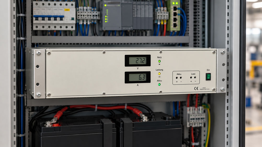
In an industrial control cabinet, a 24 V buffer charger supplies a PLC, several transmitters, communication modules and relays. At the same time, a connected battery must be charged so that the control system can continue operating during a mains power failure.
Under normal operating conditions, the connected loads require a total of 6 A. A buffer charger with an output current of 8 A therefore initially appears sufficient.
However, a problem becomes apparent after a power interruption: Although the control system operates again, the battery recharges very slowly. Under certain load conditions, the supply voltage drops or the current limitation is activated.
The reason: A buffer charger often has to supply both the operating current of the connected loads and the battery charging current simultaneously. Considering only the load current may result in an undersized power supply.
Short-term inrush currents, the charging characteristic, battery capacity and the instrument’s actual current management must also be considered.
This article explains the relationships and uses a 24 V system to demonstrate how load current, charging current and the required reserves can be evaluated separately.
Table of Contents
- Power Supply Requirements in a 24 V Control Cabinet
- Operating Principle of a Buffer Charger
- Determining the Load Current
- Determining Battery Charging Current Separately
- Calculating the Combined Current Requirement Correctly
- Load Priority and Current Limitation
- Inrush Currents and Short-Term Loads
- Practical Example: Sizing a 24 V Load and Battery Charging System
- Battery Capacity and Backup Time
- Considering Battery Recharge Time
- 24 V Nominal Voltage and Actual Charging Voltage
- Charging Characteristics and Battery Chemistry
- Temperature and Charging Behavior
- Cable Length and Voltage Drop
- Circuit Protection and Deep Discharge Protection
- Behavior During a Mains Power Failure
- EMC and Power Quality
- Status Signals and Battery Condition
- Standards and Electrical Safety
- Testing and Commissioning Procedure
- Typical Faults and Troubleshooting
- Suitable ICS Products
- Conclusion
- Frequently Asked Questions
1. Power Supply Requirements in a 24 V Control Cabinet
An industrial 24 V power supply frequently operates several loads simultaneously, including PLCs, HMIs, sensors, transmitters, relays and communication devices.
With a buffered power supply, the control system should also continue operating during a short mains power failure.
The buffer charger must therefore cover two operating conditions: supplying power while mains voltage is available, including battery charging, and supplying power from the battery during a mains failure.
2. Operating Principle of a Buffer Charger
Depending on its design, a buffer charger combines a regulated DC power supply with a suitable battery charging function.
During normal mains operation, the loads are supplied while the battery is charged or maintained in its intended standby condition.
In the event of a mains failure, the battery takes over the power supply through the designated circuit.
It is important to distinguish between a complete battery backup system with protection and transfer functions and a simple automatic battery charger.
3. Determining the Load Current
The load current is determined by the actual current consumption of all loads operating simultaneously.
Both typical continuous currents and maximum operating currents should be considered.
A control cabinet with a continuous current of 6 A may require more current during startup, for example due to capacitive inputs, relays or temporarily activated drives.
Therefore, average current alone is not sufficient for correct sizing.
4. Determining Battery Charging Current Separately
The charging current depends on battery chemistry, capacity, state of charge and the specified charging characteristic.
After discharge, a higher charging current may be required than during float charging.
For safe system design, the charging current permitted by the battery manufacturer must not be exceeded.
It must also be established how much charging current the buffer charger can actually provide while the connected loads remain operational.
5. Calculating the Combined Current Requirement Correctly
In a system with a shared current-limited supply, the current required by the connected loads and the battery charging current are added together in a simplified model.
Irequired = Iload + Icharging
For example, a load current of 6 A and a charging current of 4 A require a combined current of 10 A.
However, this addition does not automatically apply to every instrument design. With separate current paths, internal charging priority or different power limits, actual behavior must be verified using the technical documentation.
6. Load Priority and Current Limitation
Some battery backup systems initially limit the battery charging current when the connected load is high. Other instruments use different current distribution or protection concepts.
Whether load prioritization is supported must be explicitly confirmed for the respective instrument configuration.
| Operating Condition | Current Requirement | Important Design Consideration |
|---|---|---|
| Normal operation, battery fully charged | Load current and possibly a small float charging current | Continuous load and supply voltage |
| Normal operation with battery recharging | Load current plus available charging current | Combined current and power limits |
| Short-term load peak during battery charging | Increased load current plus charging current | Overload capability and possible load prioritization |
| Mains power failure | Load current supplied by the battery | Discharge current, voltage behavior and backup time |
| Mains power restored | Load current plus battery recharge current | Recharge time and available current reserve |
7. Inrush Currents and Short-Term Loads
Short-term current peaks may occur when a 24 V control system is switched on.
The power supply must either withstand these peaks or be protected by suitable startup or load management measures.
If the battery is being charged during a load peak, the total current demand may exceed the rated current.
Whether a charger automatically reduces the charging current or enters current limitation depends on the specific instrument.
8. Practical Example: Sizing a 24 V Load and Battery Charging System
An industrial control system is to be supplied by a 24 V buffer charger with an external battery.
The battery must provide backup power for one hour during a mains failure. When mains power is restored, a defined charging current should also be available.
8.1 Initial Data
- Nominal voltage: 24 V DC.
- Continuous load: 6 A.
- Short-term maximum load current: 9 A.
- Desired battery charging current: 4 A.
- Required backup time: 1 hour.
- Hypothetical usable depth of discharge: 50%.
- Hypothetical design factor for discharge losses: 0.85.
- Buffer charger considered: 24 V / 12 A.
These figures are example values. In particular, battery charging current, depth of discharge and usable capacity must be verified for a real battery system.
8.2 Current Requirement During Normal Operation
For simultaneous operation, the following applies in the simplified model:
Irequired = Iload + Icharging
Irequired = 6 A + 4 A
Irequired = 10 A
With a shared continuous current limit of 12 A, the calculated result is:
12 A – 10 A = 2 A current reserve
8.3 Checking Short-Term Load Peaks
If the load current increases to 9 A while the charging current remains unchanged:
Ipeak = 9 A + 4 A
Ipeak = 13 A
This would exceed a shared current limit of 12 A by 1 A.
Assuming approved load prioritization, the instrument could temporarily reduce the charging current to a maximum of 3 A. However, this function must not be assumed without corresponding manufacturer approval.
8.4 Estimating Battery Capacity
The theoretical capacity requirement for one hour at 6 A is:
Cideal = Iload · t
Cideal = 6 A · 1 h = 6 Ah
If a usable depth of discharge of 50% and a design factor of 0.85 are assumed for an initial estimate:
Crequired = 6 Ah / (0.50 · 0.85)
Crequired ≈ 14.1 Ah
A battery capacity class of 20 Ah, for example, could therefore be a starting point.
However, actual backup time depends on the discharge characteristic, load profile, final discharge voltage, temperature and ageing. For lead-acid batteries, the capacity rating corresponding to the relevant discharge current is particularly important.
8.5 Estimating the Ideal Recharge Time
If 6 Ah has previously been discharged from the battery and 4 A is actually available during recharging:
tideal = 6 Ah / 4 A = 1.5 h
This is only a theoretical minimum estimate. Actual recharging normally takes longer due to the charging characteristic, current limitation and charging losses.
8.6 Considering Output Power
At 24 V and a combined current of 10 A, the calculated power is:
P = U · I = 24 V · 10 A = 240 W
At an assumed actual output voltage of 27 V, a current of 10 A would already correspond to 270 W.
The power limit must therefore be checked in addition to the current limit. In particular, a nominal rating of 24 V / 12 A must not automatically be interpreted as allowing 12 A at every possible charging voltage.
8.7 Summary of Results
| Parameter | Calculation | Result |
|---|---|---|
| Continuous load | Assumed | 6 A |
| Desired charging current | Assumed | 4 A |
| Combined current requirement | 6 + 4 | 10 A |
| Rated current of the considered instrument | Manufacturer specification 5326.1 | 12 A |
| Calculated current reserve | 12 – 10 | 2 A |
| Load peak with full charging current | 9 + 4 | 13 A |
| Amount exceeding the assumed current limit | 13 – 12 | 1 A |
| Theoretical backup capacity requirement | 6 A · 1 h | 6 Ah |
| Capacity including model factors | 6 / (0.50 · 0.85) | 14.1 Ah |
| Ideal recharge time | 6 Ah / 4 A | 1.5 h |
| Power at 24 V and 10 A | 24 · 10 | 240 W |
| Power at 27 V and 10 A | 27 · 10 | 270 W |
8.8 Interpreting the Results
With a continuous load of 6 A and a charging current of 4 A, the calculated combined current requirement is 10 A.
The ICS 5326.1 with a rating of 24 V / 12 A can be considered a potential candidate for this level of demand.
However, this does not constitute final approval: The charging current actually available under simultaneous load, permissible battery capacity, voltage regulation and current behavior during load peaks must be confirmed using the instrument documentation.
9. Battery Capacity and Backup Time
Battery capacity must be suitable for the required backup time and discharge current.
A capacity rating in Ah alone does not guarantee a specific backup time. Decisive factors include discharge rate, permissible final discharge voltage, temperature and battery ageing.
For safety-related systems, backup time should also be verified under unfavorable but specified operating conditions.
10. Considering Battery Recharge Time
After a mains power failure, the battery may be partially discharged.
During subsequent operation, the buffer charger must continue supplying the loads while simultaneously replenishing the battery’s energy.
Insufficient remaining charging current extends the time required to restore full backup readiness.
The required recharge time can therefore be just as important a design criterion as the backup time itself.
11. 24 V Nominal Voltage and Actual Charging Voltage
The designation 24 V refers to the system’s nominal voltage.
The voltage required to charge a battery may differ and depends, among other factors, on battery chemistry and charging phase.
The connected loads must therefore be compatible with the actual voltage range possible in the buffered power supply system.
For sensitive measuring equipment, an additional regulated power supply may be necessary.
12. Charging Characteristics and Battery Chemistry
Lead-acid, AGM, gel and lithium-ion batteries may require different charging methods.
Typical charging concepts for suitable lead-acid batteries include constant-current and constant-voltage phases.
For lithium-ion batteries, the requirements of the battery management system must also be considered.
A nominally compatible 24 V charger must not be combined with an arbitrary 24 V battery based solely on voltage.
13. Temperature and Charging Behavior
Battery temperature influences charging behavior, usable capacity and service life.
For many lead-acid batteries, suitable temperature compensation of the charging voltage is required or recommended.
Internal temperature monitoring is specified for the ICS 5326.1.
However, this does not automatically mean that an external battery temperature is measured and the charging voltage compensated accordingly.
This function must be checked separately for the specific battery and charger combination.
14. Cable Length and Voltage Drop
Voltage drops occur in cables, fuses and terminal connections between the buffer charger, battery and loads.
For a simplified two-wire copper cable, the following applies:
ΔU = I · 2 · l · ρ / A
With an example one-way cable length of 8 m, a conductor cross-section of 2.5 mm², a current of 6 A and ρ = 0.0178 Ω·mm²/m, the voltage drop is approximately 0.68 V.
With an output voltage of 24 V, only approximately 23.32 V would be available at the load under these model conditions.
Conductor cross-section, cable length and permissible voltage range must therefore be compatible. Temperature-dependent conductor resistance and additional contact resistance must also be considered.
15. Circuit Protection and Deep Discharge Protection
A battery backup system requires suitable electrical protection for the connected circuits.
The battery in particular can supply high short-circuit currents. Its current path must therefore be protected according to the system and battery requirements.
Deep discharge protection can prevent harmful excessive battery discharge.
According to its product information, the ICS 5326.1 has deep discharge protection and thermal-magnetic circuit breakers on the front panel. The specific protection coordination must be assessed for the application.
16. Behavior During a Mains Power Failure
When mains power fails, the battery must take over the supply of the designated loads.
The output voltage and available power may differ from those during mains operation.
The permissible undervoltage limits of PLCs, transmitters and communication modules must be observed.
A practical mains failure test under defined load conditions is therefore an important part of commissioning.
17. EMC and Power Quality
Switching chargers and electronic loads can generate conducted interference.
For sensitive measuring equipment, suitable power quality, correct cable routing and EMC-compliant installation are important.
Power and signal cables should be routed according to the instrument and system specifications.
Earthing, shielding and any required galvanic isolation must also be compatible with the respective power supply concept.
18. Status Signals and Battery Condition
A buffered power supply should be capable of reporting important operating conditions to the higher-level control system.
These may include mains failure, battery faults or other instrument-specific conditions.
The ICS 5326.1 has potential-free status signals. The specific conditions reported through these signals must be obtained from the relevant documentation.
Status signals alone do not verify the actual backup time.
19. Standards and Electrical Safety
The applicable safety and installation requirements must be considered for industrial power supplies and stationary battery systems.
DIN EN IEC 62485-2 covers stationary lead-acid and nickel battery installations, among other applications. DIN EN IEC 62485-5 is relevant to stationary lithium-ion batteries.
For machinery, electrical equipment requirements according to DIN EN 60204-1, or the corresponding applicable version, must also be considered.
Work on batteries and power supplies may only be performed by appropriately qualified personnel following the specified safety procedures.
20. Testing and Commissioning Procedure
The following procedure is recommended for reliable sizing and commissioning:
- Record all 24 V loads and their continuous current requirements.
- Determine load peaks that may occur simultaneously.
- Define the required backup time.
- Check battery technology and permissible charging parameters.
- Determine the required battery capacity.
- Define the charging current and recharge time required.
- Check the current and power limits of the buffer charger.
- Verify circuit protection, voltage drops and status signals.
- Measure load current and charging current under realistic conditions.
- Test and document mains failure, restart and battery recharging.
21. Typical Faults and Troubleshooting
Battery charges very slowly: Check the charging current available while the load is operating.
Supply voltage drops during startup: Check load peaks, current limitation and connecting cables.
Battery does not take over during a mains failure: Check battery condition, protection functions and the intended transfer circuit.
Loads do not restart reliably after mains power returns: Investigate startup behavior, state of charge and voltage profile.
Battery becomes unusually warm: Check charging parameters, temperature, battery condition and possible charging control faults.
Backup time is shorter than expected: Consider the actual load, final discharge voltage, capacity rating and battery ageing.
22. Suitable ICS Products
ICS Schneider Messtechnik offers buffer chargers and automatic battery chargers for industrial power supply and service applications.
For a permanently buffered 24 V power supply with an external battery, the 5326 product family is particularly relevant. Standalone battery chargers must be distinguished from complete battery backup systems.
| Product | Important Features | Typical Application |
|---|---|---|
| ICS 5326.1 | 24 V / 12 A, external battery, 19-inch system, deep discharge protection, status signals | Industrial 24 V buffered power supply subject to verified instrument and battery compatibility |
| ICS 2263.0 | Automatic charger, 24 V / 12 A, regulated charging current, reverse polarity protection | Automatic charging of suitable 24 V batteries |
| ICS 2270.0 | Automatic charger, 24 V / 6 A, selectable maximum or half charging current | Battery charging applications with lower current requirements |
22.1 ICS 5326.1 – Buffer Charger for 19-Inch Rack Systems
The ICS 5326.1 is a buffer charger for 24 V applications with an external battery.
ICS specifies a continuous current of 12 A and a continuous output power of 288 W. The input supply is 230 V AC at 50–60 Hz. Input and output are galvanically isolated.
Specified instrument functions include overvoltage protection, deep discharge protection, internal temperature monitoring and potential-free status signals.
The instrument is designed as a 19-inch rack-mounted unit with a width of 84 HP and a height of 3 U.
Before selection, the charging power actually available under simultaneous load, battery compatibility, charging characteristic and voltage requirements must be verified.
ICS 5326.1 – Product Information
22.2 ICS 2263.0 – Automatic Battery Charger
The ICS 2263.0 is an automatic battery charger for 12 V and 24 V batteries.
For 24 V operation, ICS specifies a maximum output current of 12 A and an output power of 288 W.
The instrument offers automatic charging current regulation, switching between maximum and half charging current, and automatic transition to constant-voltage operation.
It is primarily designed as a battery charger. Its suitability as part of a permanently buffered load supply must be assessed separately.
ICS 2263.0 – Product Information
22.3 ICS 2270.0 – Automatic Battery Charger
The ICS 2270.0 is also designed for 12 V and 24 V batteries.
According to ICS, an output current of up to 6 A is available at 24 V. The instrument features automatic charging current regulation, transition to constant-voltage operation and reverse polarity protection.
It is suitable for corresponding charging applications with lower charging current requirements.
Its specifications do not imply an independent buffering function with a guaranteed uninterruptible load supply.
ICS 2270.0 – Product Information
22.4 Selecting the Buffer Charger and Battery Together
For correct sizing, ICS requires information not only on load current but also on battery chemistry, capacity, permissible charging voltage, maximum charging current and required backup time.
Connection type, control cabinet temperature, load peaks and required status signals are also relevant.
Instrument specifications concerning internal temperature monitoring do not replace verification of any required battery temperature compensation.
Battery Chargers and Buffer Chargers at ICS Schneider Messtechnik
23. Conclusion
A buffer charger frequently has to supply the 24 V loads and charge a battery at the same time.
If only the continuous load is considered, the power supply may be undersized, particularly during recharging after a mains failure.
For initial sizing, load current and desired charging current must be determined separately and then evaluated according to the actual instrument design.
Load peaks, battery chemistry, backup time, recharge time, voltage drop and protection functions must also be considered.
The most important rule is: Do not consider only the 24 V load current. Evaluate the complete current and power balance of the loads, charger and battery under all relevant operating conditions.
24. Frequently Asked Questions
24.1 What Is a Buffer Charger?
In a suitable configuration, a buffer charger combines the supply of connected loads with charging and maintaining a battery in a ready-to-use condition.
24.2 Why Must Load Current and Charging Current Be Calculated Separately?
Because both currents may occur simultaneously during mains operation and can affect the shared current or power limit.
24.3 How Is the Required Total Current Calculated?
In a simplified system with a common power supply, the maximum load current is added to the intended charging current. Actual current distribution depends on the instrument.
24.4 Is a 10 A Buffer Charger Sufficient for a 6 A Load and 4 A Charging Current?
The calculated requirement is 10 A. Higher capacity may be necessary to accommodate load peaks, voltage conditions and reserves.
24.5 Can the Battery Be Charged While the Loads Are Operating?
Yes, provided the buffer charger is explicitly designed for simultaneous operation and the available current and power limits are observed.
24.6 What Happens if the Load Is Too High?
Depending on the instrument, the charging current may be reduced, current limitation may be activated or a protection function may be triggered.
24.7 What Does Load Prioritization Mean?
The instrument distributes the available power according to a defined strategy, for example giving priority to the connected loads.
24.8 How Is the Required Battery Capacity Determined?
From the load profile and backup time, taking into account the actual discharge characteristic, permissible depth of discharge, temperature and ageing reserve.
24.9 Are 24 V Battery Voltage and Charging Voltage Identical?
No. The actual charging and float charging voltage depends on battery technology and state of charge.
24.10 How Long Does Recharging Take?
This depends on the amount of charge removed, the available charging current and the charging characteristic. Actual charging time is frequently longer than a simple Ah/A calculation suggests.
24.11 Why Are Inrush Currents Important?
Because loads can briefly draw significantly higher currents than during normal continuous operation.
24.12 Which Battery Is Suitable for a 24 V Backup System?
Only a battery whose chemistry, voltage, capacity and charging requirements are compatible with the intended buffer charger.
24.13 Must Battery Temperature Be Considered?
Yes. Temperature affects capacity and charging behavior. For certain batteries, suitable temperature compensation of the charging voltage is required.
24.14 What Is the Purpose of Deep Discharge Protection?
It is intended to prevent the battery from being discharged beyond its permissible depth of discharge.
24.15 What Happens During a Mains Power Failure?
In a suitable backup system, the battery takes over the supply of the connected loads through the designated transfer circuit.
24.16 Which ICS Buffer Charger Is Available for 24 V?
The ICS 5326.1 is a 24 V buffer charger for 19-inch rack systems, with a continuous current of 12 A and an external battery.
24.17 Are the ICS 2263.0 and 2270.0 Chargers Complete Backup Systems?
They are listed as automatic battery chargers. A complete uninterruptible load supply must not be assumed without an appropriate system assessment.
24.18 What Information Does ICS Need to Prepare a Quotation?
The required information includes nominal voltage, continuous load, load peaks, desired charging current, battery chemistry, capacity, backup time, recharge time, mounting method, ambient temperature and required protection and status functions.