


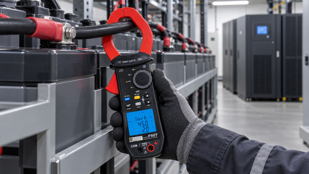
During maintenance of an uninterruptible power supply (UPS), it is observed that individual batteries are becoming unusually warm. The charging voltage is within the specified limits, and the UPS reports no faults.
However, an additional current measurement reveals an unusually high alternating current component in the battery string. Although the battery operates predominantly with direct current, an alternating component known as ripple current is superimposed on the DC current.
This can be caused, for example, by rectification in the charger, DC link regulation or the UPS inverter.
Increased ripple current can cause additional battery heating and reduce battery service life. However, the decisive factor is the actual AC component flowing through the battery string.
Measuring only at the charger output does not always provide the necessary information. Selecting the correct current clamp and distinguishing between AC-RMS, DC and AC+DC are also important.
This article explains the safe measurement setup, interpretation of the results and evaluation based on manufacturer requirements.
Table of Contents
- Identifying Ripple Current in a UPS
- Direct Current and Superimposed Alternating Current
- How Ripple Current Is Generated
- Selecting the Correct Measuring Point in the Battery String
- Distinguishing AC-RMS, DC and AC+DC
- Selecting a Suitable Current Clamp
- Considering Frequency Range and Waveform
- Practical Example: Calculating Ripple Current and Cell Stress
- VRLA, Lead-Acid and Lithium Batteries
- Evaluating Permissible Ripple Current
- Checking the Charger and Rectifier
- Influence of the UPS Inverter
- Measuring Parallel Battery Strings Correctly
- Battery Temperature and Additional Heating
- Internal Resistance and Cell Condition
- Distinguishing Ripple Voltage from Ripple Current
- Analyzing Waveforms and Frequency Spectra
- Considering Load Conditions and Charging Operation
- Electrical Safety of UPS Batteries
- Systematic Testing Procedure
- Typical Measurement Errors and Troubleshooting
- Suitable ICS Products
- Conclusion
- Frequently Asked Questions
1. Identifying Ripple Current in a UPS
UPS batteries store electrical energy and supply connected loads in the event of a mains power failure.
During normal mains operation, many battery systems are maintained at their intended state of charge by a battery charger.
Alternating current components may be superimposed on the battery current. These are referred to as ripple current or AC ripple.
Current magnitude, frequency, battery temperature and operating conditions must be considered when assessing battery condition.
2. Direct Current and Superimposed Alternating Current
The actual battery current can be simplified as the sum of a direct current component and a time-varying alternating current component.
i(t) = IDC + iAC(t)
The DC component describes the average charging or discharging current, for example.
The AC component fluctuates around this average value and may be present even when the UPS appears to be operating normally.
For battery manufacturers, the RMS value of the superimposed AC component is often the decisive parameter.
3. How Ripple Current Is Generated
Ripple current results from time-varying current and voltage waveforms in power electronics.
Typical influencing components include rectifiers, switched-mode power supplies, DC link capacitors and the control system of the UPS inverter.
The magnitude of the AC component depends on factors such as circuit topology, filtering and the respective operating conditions.
Aged filter capacitors or faulty power electronics can also contribute to increased AC components.
4. Selecting the Correct Measuring Point in the Battery String
To assess battery loading, the current actually flowing through the respective battery string must be measured.
A suitable measuring point may be located on a sufficiently accessible individual conductor of the battery string.
If the current clamp is placed around both the positive and negative conductors simultaneously, the opposing currents may largely cancel each other out.
A measurement at the overall charger output is not automatically identical to the battery current, as the UPS may have additional current paths.
5. Distinguishing AC-RMS, DC and AC+DC
Three different current quantities must be distinguished when measuring ripple current.
| Measured Quantity | Meaning | Important Consideration |
|---|---|---|
| DC current | Average charging or discharging current | Does not describe the superimposed ripple current |
| AC-RMS current | RMS value of the alternating current component | Often the relevant parameter for ripple current assessment |
| AC+DC RMS | Total RMS value including the DC component | Must not be confused with AC ripple current |
| Ripple voltage | Alternating voltage component superimposed on the DC voltage | Does not directly indicate the battery current |
| Peak value | Maximum absolute value or signal peak | Must not be equated with RMS |
A True-RMS measuring instrument can correctly evaluate distorted waveforms within its specified bandwidth. However, this alone does not guarantee sufficiently accurate measurement of a small AC component in the presence of a significantly larger DC current.
6. Selecting a Suitable Current Clamp
A suitable current clamp is frequently used to perform measurements without disconnecting the battery cable.
Important criteria include AC-RMS capability, DC measuring range, resolution, accuracy, frequency bandwidth and behavior in the presence of superimposed DC current.
An AC-only current clamp must be explicitly suitable for the specific measurement application. With certain transducer principles, a high DC component can influence the measurement.
The clamp opening diameter and safe accessibility of the individual conductor are also relevant.
7. Considering Frequency Range and Waveform
Ripple current can contain different frequency components.
These arise from factors including mains frequency, rectifier topology and the switching frequency of the power electronics.
For example, three-phase six-pulse rectification can produce frequency components around 300 Hz in a 50 Hz mains system.
Switching-frequency components may occur at significantly higher frequencies.
A measuring instrument with limited bandwidth may therefore indicate only part of the actual ripple current.
The relevant bandwidth must consequently match the testing objective and manufacturer limits.
8. Practical Example: Calculating Ripple Current and Cell Stress
A hypothetical UPS battery string consists of 96 VRLA cells connected in series, each with a nominal capacity of 100 Ah.
During float charging, the superimposed AC-RMS current is measured.
8.1 Initial Data
- Battery capacity: 100 Ah.
- Number of cells connected in series: 96.
- Measured average DC current: 1.0 A.
- Measured AC ripple current: 6.0 A RMS.
- Example manufacturer limit: 5.0 A RMS per 100 Ah.
- Assumed effective loss resistance per cell: 5 mΩ.
- Simplified steady-state assessment without additional loss mechanisms.
The cell count, current and resistance values are hypothetical. The ripple limit used is an example from the operating information of a VRLA battery manufacturer and is not a universally applicable requirement.
8.2 Comparing the Limit Value
The measured ripple current is 6.0 A RMS.
The ratio to the example limit is calculated as follows:
R = IAC / ILimit · 100%
R = 6.0 / 5.0 · 100%
R = 120%
The measured AC-RMS current is therefore 20% above the assumed limit.
8.3 Calculating the Total RMS Current
If the AC component has a mean value of zero, the following applies:
IAC+DC,RMS = √(IDC² + IAC,RMS²)
IAC+DC,RMS = √(1.0² + 6.0²)
IAC+DC,RMS ≈ 6.08 A
These two quantities must not be confused: For the example ripple limit, the relevant value is 6.0 A AC-RMS, not the total RMS value of 6.08 A.
8.4 Estimating Additional Power Loss
For a highly simplified resistive equivalent model:
PAC = IAC,RMS² · R
With an assumed effective loss resistance of 0.005 Ω per cell:
PAC = 6.0² · 0.005
PAC = 0.18 W per cell
For 96 identical cells:
PTotal = 96 · 0.18 W
PTotal = 17.28 W
This is only a model-based estimate of additional resistive losses.
8.5 Effect of Halving the Ripple Current
If the AC-RMS current is reduced to 3.0 A under otherwise identical model conditions:
PAC = 3.0² · 0.005
PAC = 0.045 W per cell
In the simplified model, the additional power loss is reduced to one quarter.
8.6 Summary of Results
| Parameter | Calculation | Result |
|---|---|---|
| Battery capacity | Assumed | 100 Ah |
| Number of cells | Assumed | 96 |
| DC current | Assumed | 1.0 A |
| AC ripple current | Assumed | 6.0 A RMS |
| Example limit | Manufacturer-specific assumption | 5.0 A RMS |
| Percentage of limit | 6 / 5 · 100 | 120% |
| Total RMS current | √(1² + 6²) | 6.08 A RMS |
| Assumed loss resistance per cell | Assumed | 5 mΩ |
| Modeled AC power loss per cell | 6² · 0.005 | 0.18 W |
| Modeled AC power loss of the string | 96 · 0.18 | 17.28 W |
| Power loss per cell at 3 A | 3² · 0.005 | 0.045 W |
8.7 Interpreting the Results
The example manufacturer limit is exceeded by 20%. The cause should therefore be investigated.
Actual cell stress cannot be fully determined from the simplified resistive model. Battery impedance, frequency, electrochemical processes, temperature and cooling influence real operating behavior.
Increased ripple current is a diagnostic indication, but it is not, on its own, proof of a specific battery defect.
9. VRLA, Lead-Acid and Lithium Batteries
UPS systems use various battery technologies, such as valve-regulated lead-acid (VRLA) or lithium-ion batteries.
Permissible charging conditions and ripple currents differ between technologies and product families.
Particularly with lithium-ion systems, the requirements of the battery manufacturer and battery management system must be considered.
Limit values specified for VRLA batteries must not be applied to lithium-ion batteries without verification.
10. Evaluating Permissible Ripple Current
Assessment must be based on the technical documentation of the specific battery system installed.
Some VRLA battery manufacturers specify AC-RMS limits in amperes per 100 Ah of battery capacity, for example.
It is also important to establish which capacity definition and operating condition the manufacturer’s specification refers to.
A specified limit should therefore not be replaced by a generic percentage of the DC charging current.
11. Checking the Charger and Rectifier
If ripple current is unusually high, the battery charger and its output filtering should be investigated.
Possible causes include aged capacitors, unfavorable control conditions or rectifier faults.
Another check is also advisable after repairs to the power electronics.
Measurements should be performed under defined and documented operating conditions.
12. Influence of the UPS Inverter
In certain UPS topologies, the battery, rectifier and inverter are connected through common electrical structures.
Consequently, inverter operating conditions can also influence the AC component in the battery branch.
Increased ripple loading is therefore not automatically attributable to a charger fault.
The actual UPS topology and current distribution must be considered during diagnosis.
13. Measuring Parallel Battery Strings Correctly
In installations with several parallel battery strings, the total current may be distributed among the individual strings.
The distribution depends on factors such as impedance, cable routing and battery condition.
For reliable assessment, the string currents should therefore be measured individually.
A current measurement at the common busbar does not automatically replace testing each battery string.
14. Battery Temperature and Additional Heating
An increased AC component can cause additional electrical losses.
These may heat the battery and contribute to accelerated ageing under unfavorable conditions.
For VRLA batteries, elevated battery temperatures, unsuitable float charging voltage and possible thermal instability are particularly relevant.
Temperature should therefore be evaluated together with ripple current, DC charging current and ambient temperature.
15. Internal Resistance and Cell Condition
The impedance of a battery influences its behavior under time-varying current.
It depends on battery technology, state of charge, temperature, ageing and frequency.
Additional measurement of cell or battery block impedance can provide indications of changes in electrical characteristics.
However, ripple current measurement alone does not replace a comprehensive condition assessment or a required capacity test.
16. Distinguishing Ripple Voltage from Ripple Current
DC voltage ripple describes the alternating voltage component at the measuring point under consideration.
Ripple current, on the other hand, describes the alternating current component flowing through a conductor or battery string.
The two quantities are related through the frequency-dependent electrical impedance.
Therefore, the actual battery current cannot be determined from a single voltage ripple value without additional information.
17. Analyzing Waveforms and Frequency Spectra
If a current clamp measurement shows unusual values, further investigation of the waveform may be useful.
With a suitable oscilloscope and an appropriately specified current probe, time-domain waveforms and, where applicable, frequency components can be displayed.
Important requirements include sufficient bandwidth, correct scaling, safe galvanic isolation and a measurement setup suitable for the battery system.
A conventional grounded oscilloscope connection must never be connected to a live battery string without appropriate safeguards.
18. Considering Load Conditions and Charging Operation
Ripple current and charging conditions may differ between float charging, recharging after discharge and other operating states.
Changes in the connected UPS load can also influence the behavior.
For repeatable measurements, load conditions, charging phase, battery temperature and measurement time should therefore be documented.
Long-term trends are sufficiently meaningful only when measured under comparable conditions.
19. Electrical Safety of UPS Batteries
UPS battery strings can supply high DC voltages and extremely high short-circuit currents.
IEC 62485-2 is relevant to stationary lead-acid battery installations. IEC 62485-5 addresses the corresponding safety requirements for stationary lithium-ion batteries.
Even when using a non-contact current clamp, suitable access conditions, safety distances and protective measures must be observed.
Measurements on such installations may only be performed by appropriately qualified personnel in accordance with the specified operating and safety procedures.
The measuring instrument must be suitable for the voltage, environment and electrical hazards involved. Opening or disconnecting a battery string for current measurement should be avoided.
20. Systematic Testing Procedure
The following procedure is recommended for traceable ripple current testing:
- Identify the UPS topology and battery technology.
- Determine manufacturer limits and permissible measurement conditions.
- Assess operating conditions and electrical hazards.
- Select a suitable measuring instrument with the required bandwidth.
- Identify an accessible individual conductor of the battery string.
- Measure DC current and AC-RMS current separately.
- Document the measured values under defined operating conditions.
- Compare other battery strings if necessary.
- Consider battery temperature and charger condition.
- Evaluate the results according to manufacturer specifications.
21. Typical Measurement Errors and Troubleshooting
Current clamp indicates almost zero amperes: Check whether both the outgoing and return conductors have accidentally been enclosed together.
AC-RMS and AC+DC are confused: Check the measuring mode and the manufacturer’s definition.
Ripple value appears unusually low: Check frequency bandwidth, resolution and performance with superimposed DC current.
Ripple current is only abnormal at high UPS load: Investigate load dependence and inverter operation.
Several battery strings show different values: Evaluate current distribution, cable routing and battery condition.
Battery temperature increases: Investigate ripple current, charging settings, ambient temperature and other possible causes together.
22. Suitable ICS Products
ICS Schneider Messtechnik offers current clamps and measuring instruments for AC/DC measurements as well as the analysis of electrical waveforms.
| Product | Important Functions | Typical Application |
|---|---|---|
| Chauvin Arnoux F407 | AC/DC/AC+DC True-RMS, ripple function, harmonics, data logger | AC and DC current testing and further analysis with suitable bandwidth |
| Chauvin Arnoux F607 | Up to 2,000 A AC / 3,000 A DC, ripple function, data recording | Current measurement on larger conductors and high-power installations |
| Chauvin Arnoux F205 | 600 A AC / 900 A DC, True-RMS, electrical testing and power measurement functions | AC/DC current measurements during servicing; suitability for small ripple components must be checked separately |
| Chauvin Arnoux OX 9304 | Four-channel digital oscilloscope, isolated channels, signal recording | Analysis of current waveforms using a suitable current probe and measurement setup |
22.1 Chauvin Arnoux F407
The F407 is a True-RMS clamp meter with AC, DC and AC+DC measurement functions.
It enables current measurements up to 1,000 A AC and 1,500 A DC and also provides harmonic analysis, measurement data storage and a ripple function.
For battery current testing, particular consideration must be given to the actual AC-RMS current displayed, the specified bandwidth and the instrument’s sensitivity to superimposed DC current.
Chauvin Arnoux F407 – Product Information
22.2 Chauvin Arnoux F607
The F607 is a True-RMS clamp meter for high currents, with a jaw opening diameter of 60 mm.
It provides AC, DC and AC+DC functions, ripple measurement, harmonic analysis and data recording.
The AC current measuring range extends up to 2,000 A, while the DC current measuring range extends up to 3,000 A.
For small ripple currents, it must be verified whether resolution, accuracy and frequency range are sufficient for the respective battery test.
Chauvin Arnoux F607 – Product Information
22.3 Chauvin Arnoux F205
The F205 provides True-RMS current measurement for AC and DC, along with additional multimeter and analysis functions.
It is designed for current measurements up to 600 A AC and 900 A DC.
For targeted measurement of a small AC component in a battery conductor carrying predominantly DC current, the specific measurement accuracy must be verified.
Chauvin Arnoux F205 – Product Information
22.4 Chauvin Arnoux OX 9304
The OX 9304 is a portable digital oscilloscope with four isolated channels and comprehensive signal recording functions.
It can be used with suitable, compatible current measurement equipment for further analysis of current waveforms.
For measurements on a battery string, the permissible electrical loading, measurement accessories and safe galvanic isolation must be explicitly suitable.
Chauvin Arnoux OX 9304 – Product Information
Additional Electrical Measuring and Testing Instruments at ICS Schneider Messtechnik
23. Conclusion
Ripple current in UPS battery strings is an important additional parameter for assessing battery operation and the connected power electronics.
The decisive factor is measuring the actual AC-RMS current in the battery string. This must be distinguished from the DC charging current, total AC+DC RMS current and ripple voltage.
Excessive AC components can contribute to additional heating and accelerated battery ageing.
For a reliable assessment, the specific battery manufacturer, permissible limits, measurement bandwidth and operating conditions must be considered.
The most important rule is: Measure ripple current directly in the relevant battery string using suitable True-RMS measuring technology and evaluate it only against the applicable battery specifications.
24. Frequently Asked Questions
24.1 What Is Ripple Current in a UPS Battery?
A time-varying alternating current component superimposed on the average direct current in the battery string.
24.2 What Causes Ripple Current?
It can be generated by rectifiers, chargers, inverters and other power electronic components.
24.3 Why Is Ripple Current a Problem for Batteries?
Excessive AC components can cause additional losses and battery heating.
24.4 Which Measurement Parameter Is Important?
Often the RMS value of the AC component, expressed in amperes AC-RMS.
24.5 Is Ripple Current the Same as Charging Current?
No. The average charging current is a DC component. Ripple current refers to the superimposed AC component.
24.6 What Does AC+DC RMS Mean?
The total RMS value of a current signal, including both its DC and AC components.
24.7 Where Is Ripple Current Measured?
On a suitable individual conductor of the respective battery string.
24.8 Can Ripple Current Be Measured at the Charger Output?
A measurement there is useful for analyzing the charger, but it does not necessarily correspond to the actual current in the battery string.
24.9 Can a Standard Current Clamp Be Used?
Only if its measurement functions, accuracy, DC compatibility and bandwidth are suitable for the specific ripple current measurement.
24.10 Why Is True-RMS Required?
To correctly evaluate the RMS value of non-sinusoidal AC components within the specified frequency range.
24.11 What Ripple Limits Apply to VRLA Batteries?
The limits are manufacturer-specific. Some manufacturers specify values such as 5 A RMS per 100 Ah of battery capacity.
24.12 Do the Same Limits Apply to Lithium-Ion Batteries?
No. The requirements of the respective battery technology and manufacturer apply.
24.13 What Frequencies Can Occur in Ripple Current?
For example, mains-frequency-related components and higher frequencies generated by switching power electronics.
24.14 Can Ripple Current Increase Battery Temperature?
Yes. Additional AC losses can cause heating and contribute to accelerated ageing under unfavorable conditions.
24.15 Is High Ripple Voltage the Same as High Ripple Current?
No. Voltage and current are related through the frequency-dependent impedance of the system.
24.16 Which ICS Instruments Are Suitable for Ripple Investigations?
Examples include Chauvin Arnoux F407 and F607 current clamps with AC/DC measurement, True-RMS technology and a ripple function. Suitability for the specific battery current must be verified.
24.17 What Safety Requirements Apply to UPS Batteries?
Important considerations include high DC voltages, possible short-circuit currents and battery-technology-specific safety requirements, for example according to IEC 62485.
24.18 What Information Does ICS Need to Prepare a Quotation?
The required information includes battery technology, battery voltage, capacity, number of strings, expected DC and AC currents, relevant frequencies, conductor dimensions, measurement accuracy and electrical safety requirements.