


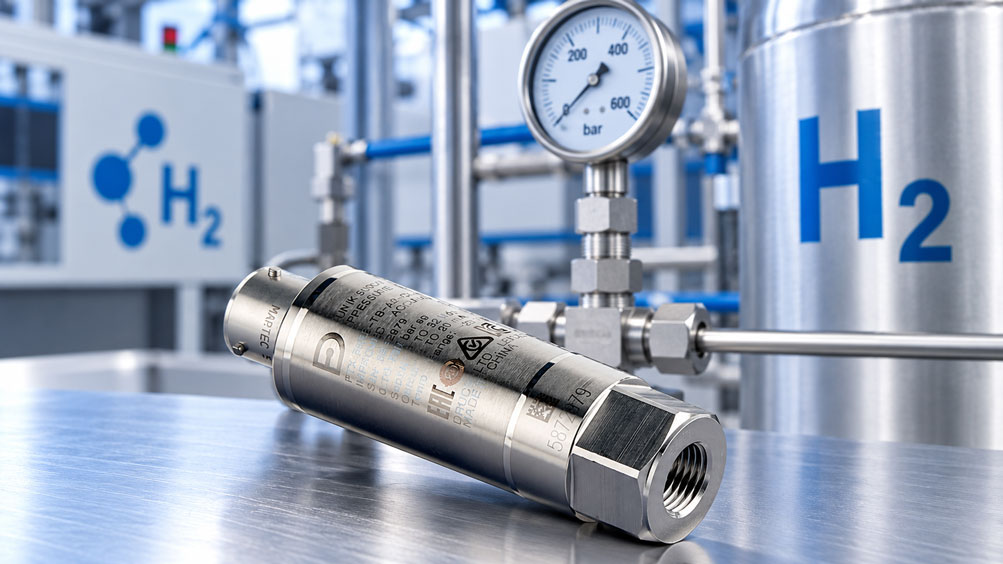
Replacing a pressure sensor on a hydrogen test bench involves more than routine maintenance. Opening the process connection interrupts the integrity of the hydrogen-carrying system. After installing a replacement sensor, it must therefore be demonstrated that the measurement point is leak-tight, the sensor provides correct measured values and the required monitoring and safety functions operate reliably.
Hydrogen places particular demands on materials, seals, pressure resistance and measurement technology. Additional challenges include potentially rapid pressure changes, low leakage rates and the risk of forming flammable gas mixtures.
Proper recommissioning therefore follows a defined sequence: Verify installation and hydrogen compatibility, demonstrate leak-tightness, check the zero point and measurement signal, test protective functions and formally authorize recommissioning with appropriate documentation.
This technical article explains the procedure for industrial H₂ test benches used in electrolysis, fuel cell technology, hydrogen storage and research. The specific test conditions must always be established by qualified personnel based on the plant-specific safety and testing documentation.
Table of Contents
1. Why Sensor Replacement Requires Renewed Authorization
Pressure sensors on hydrogen test benches monitor parameters such as supply pressures, storage pressures and dynamic pressure profiles. Their measured values may be used for process control or to trigger safety-related functions.
Replacing a sensor involves changing at least one pressure-retaining connection and often the electrical connection as well. This introduces potential new sources of error.
A mechanically correct sensor installation does not automatically mean that the electrical configuration is correct. Conversely, a plausible output signal does not confirm the leak-tightness of the process connection.
Recommissioning authorization must therefore cover mechanical integrity, measurement functionality and all safety functions affected by the intervention.
2. Special Properties of Hydrogen
Hydrogen is a colorless, odorless, very light and highly flammable gas. It has high diffusivity and can escape through small leaks.
Under certain pressure, temperature and material conditions, hydrogen can also contribute to the degradation of metallic components. The hydrogen compatibility of a material must therefore not be evaluated solely on the basis of its general stainless steel designation.
Material selection, sealing geometry and mechanical fatigue are particularly important in test systems operating at high pressures or with frequent pressure cycling.
In the event of leakage, hydrogen may accumulate preferentially in elevated areas or poorly ventilated enclosure sections. Gas detection, ventilation and ignition source prevention must therefore be adapted to the equipment geometry.
3. What Changes When a Sensor Is Replaced?
Replacing a pressure sensor may involve changes not only to the device itself but also to the seal, connection geometry, measuring range and electrical interface.
Even when the replacement sensor has the same model designation, different order configurations may vary in output signal, accuracy, overload limit or material specification.
Before recommissioning, the original and replacement device versions must therefore be compared.
Particularly important parameters include measuring range, process connection, wetted materials, pressure type, output signal, electrical connection and required approvals.
4. Establishing Safe Equipment Conditions Before Testing
Before sensor replacement and subsequent testing begin, the equipment must be placed in a safe maintenance condition in accordance with its operating instructions.
This includes controlled isolation of energy and gas supplies, verification of a suitable pressure condition and the necessary safeguards against unintended restart.
Hydrogen removal and preparation for renewed gas pressurization must be carried out using the designated equipment functions. A pressurized connection must never be depressurized by uncontrolled loosening of a fitting.
Authorization procedures, responsibilities, gas monitoring and any required work permits must be established in advance.
5. Hydrogen Compatibility of Sensors and Materials
A pressure sensor may only be used if its wetted materials are suitable for the intended hydrogen application.
In particular, the measuring diaphragm, process connection, welded joints, seals and any pressure transmission fluids must be checked.
Suitability depends on hydrogen pressure, temperature, gas purity, pressure cycles and the specific sensor construction.
Sensors developed for hydrogen applications, such as the Druck UNIK 5000H, use adapted materials and design measures to limit hydrogen-related effects.
Important: ATEX approval does not automatically confirm the hydrogen compatibility of all wetted materials. Both requirements must be verified separately.
6. Process Connections and Mechanical Installation
The process connection must match the specified sealing geometry. Thread type, insertion depth, sealing surfaces and prescribed tightening torque must be checked against the relevant manufacturer documentation.
In hydrogen-carrying connections, even minor damage to the sealing surface or unsuitable sealing materials can compromise the required leak-tightness.
Mechanical stresses caused by piping, vibration or thermal expansion must also be considered.
Only suitable and approved seals and installation aids may be used for reinstallation.
The pressure-retaining connection may only be released for further commissioning after installation and inspection have been completed.
7. Testing Strategy for Recommissioning
Reliable recommissioning authorization consists of several independent tests.
| Test | Test Objective | Important Distinction |
|---|---|---|
| Identity and material verification | Confirm suitability of the replacement sensor | Identical dimensions alone are insufficient |
| Installation inspection | Confirm correct mechanical installation | Does not confirm leak-tightness |
| Leak test | Evaluate leakage from the restored system | Does not verify measurement accuracy |
| Zero-point verification | Check the signal under defined zero conditions | Does not verify the entire measuring span |
| Signal and reference verification | Evaluate measured value transmission and deviation | Does not verify mechanical leak-tightness |
| Functional test | Check limits, alarms and interlocks | Scope depends on the safety function |
| Documented authorization | Confirm overall results and operational readiness | Only after all release criteria have been met |
The sequence, scope and acceptance criteria of these tests must be adapted to the specific installation.
8. Practical Example of Pressure Signal Verification
8.1 Initial Data
On a hypothetical hydrogen test bench, a pressure transmitter with a gauge pressure measuring range of 0 to 100 bar is replaced.
The new sensor has a linear 4–20 mA output signal. The electrical measurement chain is to be verified using defined pressure values and a suitable pressure reference.
The example assumes that mechanical safety and the necessary test conditions have already been established. Pressure testing is performed exclusively with a test medium approved for this purpose.
8.2 Calculation Basis
The following equation applies to linear pressure scaling:
p = (I – 4 mA) / 16 mA × 100 bar
The output current is calculated as follows:
I = 4 mA + (p / 100 bar) × 16 mA
8.3 Calculating the Expected Signal
At a reference pressure of 50 bar, the ideally scaled transmitter must provide the following current:
I = 4 mA + (50 bar / 100 bar) × 16 mA
I = 12.00 mA
8.4 Actual Measured Signal
Assume that the current measurement at 50 bar produces a value of 12.08 mA.
The resulting calculated pressure indication is:
p = (12.08 mA – 4 mA) / 16 mA × 100 bar = 50.50 bar
8.5 Measurement Deviation
The deviation from the reference pressure is:
Δp = 50.50 bar – 50.00 bar = +0.50 bar
Relative to the measuring span of 100 bar, this corresponds to:
0.50 bar / 100 bar × 100% = 0.50% of measuring span
8.6 Summary of Results
| Reference Pressure | Expected Signal | Measured Signal | Indicated Pressure |
|---|---|---|---|
| 0 bar | 4.000 mA | 4.016 mA | 0.10 bar |
| 25 bar | 8.000 mA | 8.032 mA | 25.20 bar |
| 50 bar | 12.000 mA | 12.080 mA | 50.50 bar |
| 75 bar | 16.000 mA | 16.048 mA | 75.30 bar |
| 100 bar | 20.000 mA | 20.000 mA | 100.00 bar |
8.7 Interpreting the Results
The example demonstrates that a correctly connected sensor may still exhibit a measurable deviation.
Whether the deviation of +0.50 bar is permissible depends on the device specification, the measurement uncertainty of the reference and the plant-specific acceptance criteria.
The figures are exclusively hypothetical calculation values. They do not represent manufacturer specifications or permissible limits for hydrogen test benches.
The result also does not confirm the leak-tightness of the process connection. This must be verified independently.
9. Distinguishing Pressure Testing from Leak Testing
Pressure testing and leak testing serve different purposes.
A pressure strength test demonstrates that a pressure-retaining system can safely withstand the specified test load under the defined conditions.
A leak test, on the other hand, demonstrates that a connection or system meets the specified leakage requirements.
After sensor replacement, the applicable test procedure must be used to determine which tests must be repeated and which section of the system is affected.
Passing a pressure hold test does not automatically provide complete proof of leak-tightness. Pressure and temperature changes, as well as the detection limit of the method, can influence the result.
10. Leak Testing After Sensor Replacement
After installation, the restored pressure-retaining connection must be tested for leaks according to an approved procedure.
Depending on the system, this may involve testing with an inert gas, suitable leak detection methods or other qualified procedures.
The selection depends on factors including the required leakage detection capability, pressure level, geometry and sensitivity of the test method.
The test medium, test pressure, temperature stabilization, permissible leakage rate and test duration must not be specified universally.
Particularly for hydrogen systems, it must be ensured that the procedures and test equipment used are suitable for the intended application.
Any abnormal leak test result must be investigated and its cause eliminated before authorization is granted. Electrical sensor functionality cannot replace the required proof of leak-tightness.
11. Inerting, Purging and Gas Quality
After opening a hydrogen-carrying system, air may enter the affected section. Before hydrogen is reintroduced, the required gas condition must therefore be established and verified.
Plant-specific inerting and purging procedures may be required for this purpose.
The purge gas must be compatible with the materials, process conditions and any applicable gas purity requirements.
In fuel cells, electrolyzers and high-purity hydrogen systems, moisture, oxygen and other contaminants may also be relevant.
A successful leak test does not automatically confirm the required gas purity or an adequate purging condition.
Evaluation must be based on the approved operating instructions and suitable measurement or verification methods.
12. Checking the Zero Point Under Defined Conditions
Zero-point verification must be performed under the pressure condition defined for the respective sensor type.
For a gauge pressure transmitter with a measuring range of 0 to 100 bar, the ideal zero point of a linear 4–20 mA signal normally corresponds to 4 mA.
For absolute pressure sensors, it must be considered that the physical pressure zero point does not correspond to normal atmospheric pressure.
An apparent residual pressure may result from trapped pressure, temperature influences, mechanical hysteresis or sensor effects.
Under certain conditions, hydrogen sensors may also exhibit time-dependent effects following prolonged exposure to pressure.
Zero adjustment should therefore not be performed automatically whenever a deviation occurs. The cause must first be identified and the permissible deviation evaluated.
13. Measurement Accuracy and Pressure References
Zero-point verification alone does not confirm accuracy across the entire measuring range.
Suitable pressure references are used for metrological verification. The test conditions must be appropriate for the measurement task, pressure type and permissible test medium.
The evaluation must consider the accuracy of the device under test, the measurement uncertainty of the reference and the required operational tolerances.
Calibration documents the deviations identified. Adjustment, on the other hand, changes the relationship between pressure and output signal.
After sensor replacement, it must be determined whether a documented functional test is sufficient or whether additional calibration evidence is required.
14. Electrical Output Signals and PLC Scaling
A new pressure transmitter may have the same electrical output as its predecessor but use a different pressure measuring range.
If a previously installed 0–250 bar sensor is replaced with a 0–100 bar sensor, the signal assignment in the control system must be adapted and verified.
Particular attention must be paid to the assignment of 4 and 20 mA, the pressure unit used, polarity and, where applicable, fault current signaling settings.
The test should compare the actual sensor signal with the corresponding indication on the test bench.
If deviations occur, configuration, power supply, current loop and input scaling should be investigated first.
15. Digital Communication and Diagnostics
Depending on the pressure sensor, digital communication interfaces may be available in addition to analog current or voltage signals.
On suitable devices, these enable the transmission of measured values, device status and diagnostic information, among other data.
After replacement, the interface used, communication parameters and measured value assignment must be checked.
The handling of sensor faults and communication failures in the higher-level test bench control system must also be considered.
A digital status message indicating “ready for operation” confirms neither mechanical leak-tightness nor automatically the required measurement accuracy.
16. Considering Pressure Dynamics and Load Changes
Hydrogen test benches may generate rapid pressure increases, pressure drops and frequently recurring load changes.
Short-term pressure peaks may occur particularly during valve switching, filling operations and dynamic fuel cell tests.
The sensor used must therefore be suitable not only in terms of its measuring range but also with regard to overload capability, pressure cycling resistance and response characteristics.
A slow measurement signal may be unable to adequately capture short-term pressure peaks. Conversely, unsuitable signal filtering can make evaluation more difficult.
For dynamic applications, the Druck UNIK 5000H, developed specifically for hydrogen, is available in suitable versions with high signal bandwidth.
Actual suitability must be verified based on the complete measurement chain and the required time resolution.
17. Checking Hydrogen Gas Detection Systems
Hydrogen is odorless and cannot be reliably detected without suitable measurement technology.
Stationary or portable gas detectors and additional monitoring equipment may therefore form part of the safety concept.
Before recommissioning authorization, it must be confirmed that the gas detection functions required for the test bench are available and have been tested.
The devices must be suitable for hydrogen. A sensor designed for other combustible gases is not automatically suitable for reliable hydrogen detection.
Detector positioning depends on potential leak locations, room geometry, airflow and the safety concept.
Functional tests using suitable test gas must be performed according to the manufacturer’s instructions and the operational test schedule. A simple display check or electrical signal check does not necessarily replace verification of the gas detection function.
18. Limit Values, Interlocks and Protective Functions
Pressure sensors may be integrated into process control systems or safety-related functions.
After replacement, the affected limit monitoring functions, alarms and interlocks must be tested according to the documented safety concept.
It is particularly important to distinguish between a normal process warning and a safety-related shutdown function.
A correctly displayed pressure value does not automatically confirm that a required shutdown will operate when a limit is exceeded.
Safety-related functions must be tested using approved procedures. Temporarily bypassed functions must be restored to their prescribed condition and verified before authorization is granted.
19. Explosion Protection and Technical Documentation
Hydrogen systems may contain potentially explosive atmospheres. The required protective measures are determined by the plant-specific risk assessment and hazardous area classification.
When selecting sensors and electrical equipment, the relevant explosion protection requirements must be considered, including gas group, equipment category or equipment protection level, and temperature class.
Applicable standards may include the IEC 60079 series for explosive atmospheres.
ISO 26142 describes product requirements for stationary hydrogen detection apparatus. IEC 60079-29-2 addresses the selection, installation, use and maintenance of suitable gas detectors.
The specific standards, approvals and inspection obligations that apply depend on the plant location, design and application.
Following sensor replacement, explosion protection documentation, replacement part records and modification documentation may need to be updated.
20. Testing and Commissioning Procedure
The following procedure is recommended for structured recommissioning authorization. All work steps require plant-specific authorization and appropriate professional qualifications.
- Review the scope of work, risk assessment and applicable test instructions.
- Confirm safe equipment conditions and the required energy isolation measures.
- Verify the identity, hydrogen compatibility and technical specifications of the replacement sensor.
- Inspect mechanical installation, process connection and seals.
- Perform the required leak test using an approved procedure.
- Verify the required purging condition and, where applicable, gas quality.
- Record and evaluate the zero signal under defined conditions.
- Check electrical or digital measurement signal transmission.
- Perform the specified pressure reference and calibration checks where required.
- Test affected limit monitoring functions, gas detection functions and safety-related interlocks.
- Fully document test results, deviations and corrective measures.
- Obtain recommissioning approval from the responsible authorized party once all release criteria have been met.
- Return the test bench to its intended operating condition in accordance with the approved operating instructions and monitor its operation.
If required evidence is missing or limits are exceeded, authorization must not be granted. The cause must be identified before recommissioning.
21. Troubleshooting After Sensor Replacement
21.1 Leak Test Failed
Investigate the affected connection, sealing geometry, component design and installation in accordance with the approved test procedure. Authorization may only be granted after the cause has been eliminated and the repeated test has been completed successfully.
21.2 Zero Signal Outside Tolerance
Check the defined pressure condition, temperature, pressure type and electrical supply. Consider possible residual pressure or time-dependent zero-point recovery.
21.3 Incorrect Pressure Value in the PLC
Compare the sensor measuring range, output signal, signal wiring and control system scaling. If necessary, verify the measured value using a suitable pressure reference.
21.4 Signal Response Is Too Slow
Evaluate sensor bandwidth, electronic filtering, data acquisition and process dynamics. The complete signal chain may limit the time resolution.
21.5 Alarm or Interlock Does Not Function
Investigate the affected safety function according to the approved test instructions. Safety-related operational authorization must not be granted without the required functional verification.
22. Suitable ICS Products for Hydrogen Test Benches
ICS Schneider Messtechnik offers various sensors and components for measuring and monitoring hydrogen systems. The decisive factors are hydrogen compatibility, pressure range, measurement accuracy, pressure dynamics and the required safety functions.
22.1 Druck UNIK 5000H – Pressure Sensor for Hydrogen Applications
The Druck UNIK 5000H was specifically developed for demanding hydrogen applications.
Depending on the version, measuring ranges from 700 mbar to 700 bar are available. The series offers accuracy options down to ±0.04% of full scale using the Best Straight Line method, as well as various analog output signals.
Fast signal processing makes suitable versions particularly interesting for dynamic measurements on hydrogen test benches.
Wetted materials and design measures are adapted for hydrogen applications. Pressure connections, Ex approvals and other characteristics must be verified for the selected configuration.
22.2 IMP 336 – Welded Industrial Pressure Transmitter
The IMP 336 is an industrial pressure transmitter for technical gases and hydrogen applications.
The ICS product specifications indicate nominal pressure ranges from 0–16 bar up to 0–1000 bar and an accuracy of 0.5% FSO.
The wetted components are made from special stainless steel materials. The design is intended for demanding industrial pressure applications.
The IMP 336 is particularly suitable for applications requiring robust pressure measurement with hydrogen-compatible materials.
22.3 Druck RPS/DPS8000H – High-Precision Hydrogen Pressure Measurement
The Druck RPS/DPS8000H combines resonant pressure measurement technology with a protective design developed for hydrogen applications.
Depending on the version, the series offers accuracy down to ±0.01% FS over the compensated temperature range and long-term stability of ±100 ppm FS per year.
Different digital or frequency-based output signals enable integration into demanding measurement systems.
These sensors are particularly interesting for test benches and research applications requiring high accuracy and long-term stability. Their output interfaces must be compatible with the existing data acquisition system.
22.4 SMART 3G-C2 – Stationary Hydrogen Gas Detection
The SMART 3G-C2 is a stationary gas detector for various combustible and other gases.
Suitable catalytic or electrochemical sensor variants are listed for hydrogen.
Such a device can form part of the gas monitoring system of a hydrogen test bench. The sensor version, measuring range, Ex suitability and integration into the alarm concept must be selected for the specific project.
The gas detector monitors potential gas releases and does not replace leak testing of the pressure-retaining system.
22.5 MINIMESS 1215 – Gas Measurement and Service Connections
The MINIMESS 1215 Gas Filling Valve with DVGW Approval provides compact access for measurement and testing tasks in gas pressure systems.
ICS provides documentation for gaseous hydrogen and specifies operating pressures up to 250 bar for the corresponding product group.
Suitable versions allow defined measurement and service points to be incorporated into the system without having to reopen a process connection for every test.
Hydrogen suitability, the actual permissible pressure rating, hose connections and sealing concept must be verified for the specific version.
| Product | Key Features | Typical Application |
|---|---|---|
| Druck UNIK 5000H | Hydrogen-optimized pressure sensor, analog signals | Static and dynamic pressure measurement |
| IMP 336 | Welded stainless steel pressure transmitter | Robust pressure monitoring |
| RPS/DPS8000H | Resonant precision pressure sensor, digital or frequency-based outputs | High-accuracy test bench measurements |
| SMART 3G-C2 | Stationary gas detector with suitable H₂ sensor variants | Hydrogen gas monitoring |
| MINIMESS 1215 Gas | Gas measurement and service connection | Defined test and measurement access points |
Additional sensors, flowmeters and components for H₂ applications are available in the ICS Hydrogen Solutions product category.
Further information on device selection is provided in the technical article Selecting a Hydrogen Pressure Sensor: Evaluating Materials, Seals and Approvals Correctly.
23. Conclusion
After replacing a pressure sensor on a hydrogen test bench, several different requirements must be fulfilled.
The leak test confirms that the restored connection meets the specified leakage requirements. Zero-point and signal verification evaluate the measurement function. In addition, the affected gas detection, monitoring and safety functions must be checked.
Passing an individual test does not replace a complete authorization assessment.
The most important rule is: First verify hydrogen compatibility and mechanical leak-tightness, then check measurement functionality and finally confirm all required safety functions.
Recommissioning may only take place after all plant-specific release criteria have been met and documented.
24. FAQ – Frequently Asked Questions About Recommissioning Hydrogen Test Benches
24.1 Is a Leak Test Required After Every Sensor Replacement?
If a hydrogen-carrying pressure-retaining connection has been opened, the required leak-tightness must be demonstrated before recommissioning in accordance with the applicable plant requirements.
24.2 Why Are Hydrogen Test Benches Particularly Demanding?
Hydrogen has high diffusivity, is highly flammable and places particular demands on materials, seals and pressure measurement systems.
24.3 Can a Standard Pressure Sensor Be Used for Hydrogen?
Only if the specific sensor version is suitable and approved for the intended hydrogen, pressure and temperature conditions.
24.4 Does ATEX Approval Automatically Mean Hydrogen Compatibility?
No. Explosion protection and hydrogen compatibility of wetted materials are separate requirements.
24.5 Which Test Medium Is Used for Leak Testing?
The test medium is determined by the approved test procedure. Depending on the application, suitable inert gases may be used for hydrogen systems.
24.6 Is a Pressure Hold Test Sufficient to Demonstrate Leak-Tightness?
Not necessarily. Whether the procedure can detect the required leakage rate depends on the test conditions and detection sensitivity.
24.7 Why Must the Zero Point Be Checked?
A zero-point error can shift the entire pressure indication and therefore affect process measurements and limit monitoring.
24.8 Can the Zero Point Be Adjusted While Residual Pressure Is Present?
Conventional zero adjustment with unknown residual pressure is unsuitable because actual process pressure may be incorrectly compensated.
24.9 Is Calibration Required After Sensor Replacement?
This depends on the measurement task, available calibration evidence and operational or regulatory requirements.
24.10 What Does 4 mA Mean on a Hydrogen Pressure Sensor?
For a linear 4–20 mA transmitter, 4 mA normally corresponds to the configured lower range value.
24.11 What Happens if the PLC Scaling Is Incorrect?
The control system may display incorrect pressure values or evaluate limits at different process pressures than intended.
24.12 Must the Gas Detection System Also Be Tested?
The required gas detection functions must be available before recommissioning. The necessary scope of testing depends on the safety concept.
24.13 Can H₂ Pressure Sensors Indicate a Residual Value After Depressurization?
Yes. Under certain conditions, hysteresis, temperature or hydrogen-related time-dependent effects may cause a temporary deviation.
24.14 Why Are Pressure Peaks Important in Hydrogen Test Benches?
Rapid load changes can increase the mechanical demands on the measuring diaphragm and influence sensor selection.
24.15 Can the Sensor Signal Be Correct Even if the Connection Is Leaking?
Yes. A plausible electrical measurement does not demonstrate the mechanical leak-tightness of the process connection.
24.16 Which Documents Are Required for Recommissioning?
Typical documentation includes installation and suitability records, leak test results, measurement point verification, safety function tests where applicable, and the documented authorization decision.
24.17 Who Is Authorized to Release a Hydrogen Test Bench for Operation?
Authorization must be granted by personnel who are appropriately qualified and authorized under the applicable operational or legal requirements.
24.18 Which Pressure Sensors Are Suitable for Hydrogen Test Benches?
Depending on the application, suitable options may include the Druck UNIK 5000H, IMP 336 or RPS/DPS8000H. The decisive factors are specific hydrogen compatibility, pressure resistance, measurement accuracy and signal interfacing.