


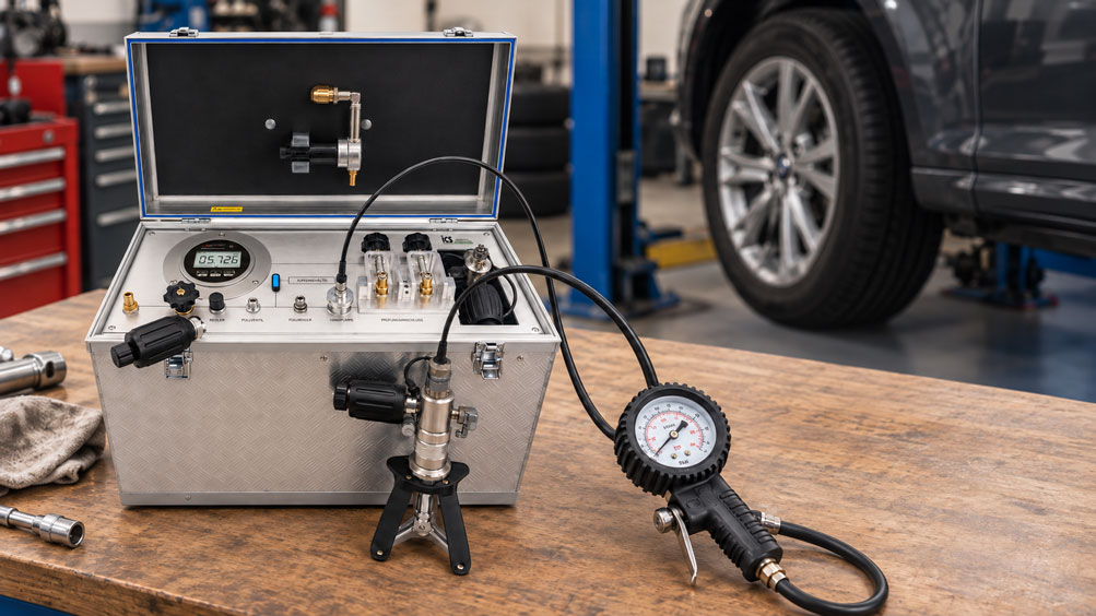
A tire inflation pressure gauge needs to be tested in an automotive workshop. The instrument is connected to a portable reference testing system, and a test pressure of 3.00 bar is applied.
Immediately after pressure generation, the indication agrees with the reference pressure gauge. However, a few minutes later, the test pressure has dropped to 2.97 bar. The test is repeated, but the pressure slowly decreases again.
Is the reference testing system leaking? Is the problem caused by the tire inflation gauge, or has the enclosed air simply cooled down?
A decreasing test pressure does not automatically indicate a leak. Particularly in pneumatic test setups, temperature equalization, hose volume, couplings and valves can influence pressure behavior.
The key is to systematically examine the individual components of the test circuit. These include pressure generation, the connection to the device under test, the tire inflation device itself and the environmental conditions.
Using the PRM-25 reference testing system as an example, this technical article explains how to identify the causes of unstable test pressures and establish reliable measurement conditions.
Table of Contents
- Understanding Test Pressure and Pressure Stability
- Structure of a Pneumatic Test Circuit
- Typical Causes of Pressure Drift
- Distinguishing Leaks from Temperature Equalization
- Checking Test Connections and Couplings
- Checking Tire Valves and Inflation Connections
- Considering Test Hoses and Dead Volume
- Practical Example: Calculating Pressure Loss Due to Cooling
- Stabilization Time Before Taking Readings
- Operating Fine Adjustment Regulators and Volume Adjusters Correctly
- Using the Buffer Vessel Effectively
- Hand Pump and External Compressed Air Supply
- Isolating the Test Circuit and Identifying Faults
- Testing Two Tire Inflation Devices Simultaneously
- Selecting Suitable Test Pressure Points
- Reference Pressure Gauge and Measurement Uncertainty
- Ambient Temperature and Direct Sunlight
- Documenting Pressure Stability
- Considering Standards and Requirements
- Working Safely with Compressed Air
- Systematic Testing Procedure and Troubleshooting
- PRM-25 and Suitable ICS Calibration Equipment
- Conclusion
- Frequently Asked Questions
1. Understanding Test Pressure and Pressure Stability
When testing a tire inflation pressure gauge, the device under test and the reference measuring instrument are subjected to the same pneumatic pressure.
To compare their indications meaningfully, the pressure must remain sufficiently stable while readings are taken.
If the pressure changes continuously, even small differences in reading times can result in apparent measurement deviations.
Before performing the accuracy test, it must therefore be established whether the test setup is sufficiently stable and leak-tight.
2. Structure of a Pneumatic Test Circuit
A typical test circuit consists of a pressure source, pressure regulation, a reference pressure gauge, connecting components and the tire inflation device under test.
A portable testing system may also include a compressed air reservoir and various valves.
All components together form the pneumatic test volume. Any leaking connection, open valve or temperature change can influence the pressure profile.
For troubleshooting, it is therefore essential to know which components are connected to one another during the actual measurement.
3. Typical Causes of Pressure Drift
Unstable test pressure can have several causes. Not all of them indicate a defective measuring instrument.
| Cause | Typical Behavior | Suitable Check |
|---|---|---|
| Leaking coupling | Pressure continues to decrease after stabilization | Inspect the connection and seal |
| Leaking tire valve | Pressure loss after connecting the device under test | Check the valve core and connection |
| Leaking tire inflation device | Test circuit becomes unstable when the device is connected | Test the device individually using suitable isolation |
| Thermal pressure equalization | Pressure changes after rapid pumping, then gradually stabilizes | Extend stabilization time and monitor temperature |
| Hose expansion | Delayed pressure change following pressure generation | Check hose length and material |
| Unintentional valve operation | Sudden pressure changes | Check valve positions and operation |
| Unsuitable pressure supply | Fluctuations during pressure readjustment | Isolate the pressure source and check regulation behavior |
Several causes may occur simultaneously. For example, the air may initially cool down while a small leak is also present at a test connection.
4. Distinguishing Leaks from Temperature Equalization
When air is compressed rapidly, its temperature increases. After pressure generation, the gas transfers heat to hoses, metal fittings and the surrounding environment.
The air temperature decreases, causing the pressure to drop even if the system is completely leak-tight.
When a pressure change is caused by temperature, the drift often decreases as thermal equilibrium is approached.
An actual leak, on the other hand, can continue to cause pressure loss even after sufficient stabilization.
The shape of the pressure-versus-time curve provides important information, but it does not constitute conclusive proof of a leak on its own.
5. Checking Test Connections and Couplings
Quick couplings and test adapters are among the components that should be checked regularly in pneumatic measurement setups.
Contaminated sealing surfaces, damaged seals or incompletely engaged connections can cause the test pressure to decrease slowly.
The PRM-25 features two Airfix connections for devices under test, equipped with retaining clamps.
During testing, these connections must be operated correctly, and the device under test must be properly connected.
A suitable leak detection method can help locate leaks at accessible connections.
6. Checking Tire Valves and Inflation Connections
Depending on their configuration, tire inflation devices use connectors suitable for the corresponding tire valves.
With Schrader-type tire valves, the valve core is mechanically opened by the appropriate connector.
An incorrectly positioned connector may actuate the valve pin insufficiently or improperly. Damaged seals can also allow air to escape.
For correct testing, the valve type, connector geometry and sealing surface must be compatible.
A leaking test connection must not be sealed by applying excessive mechanical force.
7. Considering Test Hoses and Dead Volume
Long hoses increase the enclosed air volume and can influence stabilization.
Flexible hoses in particular can expand elastically during pressure generation.
This time-dependent volume change can cause a pressure change without any gas escaping from the system.
Short, suitable hoses therefore often make precise pressure adjustment easier.
For comparative testing, hose configurations should be kept as consistent as possible.
8. Practical Example: Calculating Pressure Loss Due to Cooling
A pneumatic test circuit is adjusted to a gauge pressure of 3.000 bar. Immediately after pressure generation, the assumed temperature of the enclosed air is 25 °C.
Over the following minutes, the air cools to 24 °C.
The objective is to calculate the pressure drop that can result in a completely leak-tight, rigid and closed test volume.
8.1 Initial Data
- Initial pressure: 3.000 bar gauge pressure.
- Assumed atmospheric pressure: 1.000 bar.
- Initial gas temperature: 25 °C.
- Final temperature: 24 °C.
- No leakage.
- Constant volume and constant amount of gas.
- Ideal gas as a simplified calculation model.
All values are hypothetical examples. They do not represent a verified pressure profile of a specific PRM-25.
8.2 Calculating Absolute Pressure
The ideal gas law requires absolute pressure:
pabs = pgauge + patm
p1,abs = 3.000 + 1.000 bar
p1,abs = 4.000 bar
8.3 Converting Temperature to Kelvin
The temperatures are:
T1 = 298.15 K
T2 = 297.15 K
8.4 Calculating the Final Pressure
For constant volume and an unchanged amount of gas:
p2,abs = p1,abs · T2 / T1
p2,abs = 4.000 bar · 297.15 / 298.15
p2,abs ≈ 3.9866 bar
The resulting gauge pressure is:
p2,gauge = 3.9866 – 1.000 bar
p2,gauge ≈ 2.9866 bar
8.5 Determining the Pressure Change
The difference from the initial pressure is:
Δp = 2.9866 – 3.0000 bar
Δp ≈ -0.0134 bar = -13.4 mbar
In this idealized example, cooling by just 1 K can cause a pressure drop of approximately 13 mbar.
8.6 Comparing Pressure Profiles
In a subsequent hypothetical observation, two different pressure profiles are considered.
The first test circuit stabilizes after cooling. The second continues to lose pressure after the assumed thermal stabilization.
| Test Condition | Initial Pressure | Final Pressure | Evaluation |
|---|---|---|---|
| Immediately after pressure generation | 3.000 bar | 2.9866 bar | Thermal cooling by 1 K in the simplified model |
| After thermal stabilization | 2.9866 bar | 2.9866 bar | Stable in the model |
| Further 5 minutes with continued pressure loss | 2.986 bar | 2.976 bar | Investigate additional causes |
| Average pressure change during the final period | 10 mbar in 5 min | 2 mbar/min | Observed pressure change rate, not a specific leak rate |
8.7 Interpreting the Results
The calculation demonstrates that even a small temperature change can cause a measurable pressure drop.
The calculation assumes that the temperature of the enclosed air is known. Ambient temperature alone is not necessarily sufficient for this purpose.
In a real test circuit, additional volume changes, control processes and leaks may occur.
An observed pressure change in mbar/min cannot be directly converted into an actual gas loss expressed as volume per unit of time without additional information.
9. Stabilization Time Before Taking Readings
After adjusting the test pressure, the test circuit should be allowed sufficient time to stabilize.
Reference and test instrument readings should only be taken once the pressure change is within the permissible range for the measurement task.
The time required depends on the pressure change, enclosed volume, material and temperature.
There is therefore no universally applicable stabilization time for all tire inflation devices.
10. Operating Fine Adjustment Regulators and Volume Adjusters Correctly
In pneumatic test setups, initial pressure generation and final fine adjustment should be performed separately.
The hand pump is first used to generate a pressure close to the desired test point.
Final adjustment is then performed slowly using the designated fine adjustment regulator or volume adjuster.
The PRM-25 provides corresponding features for precise fine pressure adjustment.
After making an adjustment, sufficient stabilization time should be allowed again before taking a reading.
11. Using the Buffer Vessel Effectively
The PRM-25 features an integrated compressed air vessel with a volume of 2 liters.
Depending on the intended operating mode, it can be used as a compressed air reservoir or buffer.
If the buffer is actually connected to the relevant test circuit, it increases the total pneumatic volume.
In the idealized isothermal model, a given small change in the amount of gas then produces a smaller pressure change.
A larger buffer can make pressure readjustment easier. However, it does not eliminate leaks and may make small leaks less noticeable due to a slower pressure drop.
For reproducible leak detection, it is therefore important to know whether the buffer is connected.
12. Hand Pump and External Compressed Air Supply
The PRM-25 has an integrated ICP 40.2 precision hand calibration pump for generating pressures up to 40 bar.
This allows the test case to operate independently of an external compressed air supply.
Alternatively, a suitable external compressed air supply can be used via the designated connection.
When switching between these operating modes, valve positions and the parts of the pressure supply actually connected to the test circuit must be considered.
For a pressure holding test, controlled isolation from automatically regulating pressure sources is important, provided the specified test procedure permits this.
13. Isolating the Test Circuit and Identifying Faults
The most effective troubleshooting approach often involves gradually reducing the test circuit to as few components as possible.
First, the reference testing system is examined under suitable conditions without the suspected device under test.
Individual hoses, adapters or tire inflation devices are then added one at a time.
Suitable pressure-rated isolation devices and blanking connections can help test individual sections separately.
However, these additional isolation or testing options must not automatically be assumed to be standard equipment on every PRM-25.
Only components suitable for the pressure and connection type may be used.
14. Testing Two Tire Inflation Devices Simultaneously
The PRM-25 allows two tire inflation pressure gauges to be connected simultaneously to the same pneumatic test circuit.
This can simplify comparative testing because both devices under test are generally subjected to the same static pressure conditions.
However, a leak in one of the two tire inflation devices affects the common test pressure.
Operating a filling or release valve on either device also changes the condition of the shared system.
For troubleshooting, suspected devices should therefore be examined individually wherever possible.
15. Selecting Suitable Test Pressure Points
For calibration, the test pressure points must be appropriate for the measuring range and intended use of the tire inflation pressure gauge.
Typical tests include several points across the relevant measuring range and, where necessary, tests with increasing and decreasing pressure.
The test pressure must not exceed the permissible limits of the device under test or the complete measurement setup.
Pressure stability must be sufficient at every relevant test point.
16. Reference Pressure Gauge and Measurement Uncertainty
A high-resolution reference display makes it possible to observe small pressure changes.
However, this does not automatically mean that the reference instrument itself is inaccurate or unstable.
The current version of the PRM-25 uses an ADT681 precision digital pressure gauge.
The reference measuring range should be selected according to the required test points and tolerances.
The PRM-25 is available with reference measuring ranges of 6, 10, 16, 25 or 40 bar.
Resolution, accuracy and calibration uncertainty must be distinguished from one another.
17. Ambient Temperature and Direct Sunlight
Portable tests are frequently performed under changing environmental conditions.
Direct sunlight on the test case, cold compressed air or moving between a heated workshop and an outdoor environment can influence thermal equalization.
Heating of a hose through contact or sunlight can also change the test pressure.
For more demanding comparisons, the testing system and device under test should be operated under temperature conditions that are as stable as possible.
18. Documenting Pressure Stability
For recurring problems, the pressure profile should be documented.
Useful information includes:
- Reference instrument used and identification of the device under test.
- Test pressure and pressure reference type.
- Time of pressure generation.
- Duration of the stabilization period.
- Reference readings at defined times.
- Environmental conditions and, where applicable, gas temperature.
- Hose and coupling configuration.
- Positions of relevant valves and buffer connection status.
This information helps determine whether an abnormality is reproducible and which component may be involved.
19. Considering Standards and Requirements
DIN EN 12645:2015-02 covers tire pressure measuring instruments used to check and adjust the pressure of motor vehicle tires.
It describes metrological requirements and tests for the corresponding instruments.
The specific applicability of normative, legal or verification requirements must be assessed for the respective tire inflation pressure gauge and its intended use.
A conventional pressure holding test does not replace complete calibration or any required statutory inspection or legal verification.
20. Working Safely with Compressed Air
Pneumatic testing systems store energy in compressed air.
Before changing hoses, couplings or devices under test, the relevant part of the system must be depressurized according to the specified safe procedure.
The maximum permissible pressures of all connected components must be observed.
Even when a testing system can generate pressures up to 40 bar, the tire inflation device under test must not be subjected to pressures exceeding its permissible limits.
Test connections and compressed air vessels must not be replaced with improvised components.
21. Systematic Testing Procedure and Troubleshooting
The following sequence is recommended when the test pressure is unstable:
- Identify the device under test, measuring range and pressure limits.
- Visually inspect the test case, hoses and couplings.
- Avoid unnecessary connection and hose volumes.
- Generate the test pressure in a controlled manner.
- Perform fine adjustment using the designated regulator.
- Allow an appropriate stabilization time.
- Observe the pressure profile using the reference instrument.
- Evaluate temperature changes as a possible cause.
- Examine suspected devices and connections individually.
- Determine the actual measurement deviation only after sufficient stability has been achieved.
If leaks cannot be clearly located, the reference testing system itself should first be examined under defined conditions.
22. PRM-25 and Suitable ICS Calibration Equipment
The PRM-25 reference testing system from ICS Schneider Messtechnik was specifically developed for testing and calibrating tire inflation pressure gauges.
It combines pressure generation, reference measurement, test connections and fine pressure regulation in a portable test case.
| Component | Function | Importance for Unstable Test Pressure |
|---|---|---|
| ADT681 precision digital pressure gauge | Reference pressure measurement | Detection and observation of small pressure changes |
| ICP 40.2 precision hand calibration pump | Manual pressure generation up to 40 bar | Controlled initial pressure generation |
| Fine adjustment regulator / volume adjuster | Precise pressure adjustment | Fine approach to and adjustment of test points |
| Integrated 2-liter compressed air vessel | Buffer and compressed air reservoir | Can support pressure regulation and stability when suitably connected |
| Two Airfix test connections | Connection of two tire inflation pressure gauges | Couplings and connected devices must be considered as possible leak points |
| External compressed air connection | Alternative pressure supply | Pressure source and regulation must be considered during troubleshooting |
22.1 PRM-25 – Reference Testing System for Tire Inflation Pressure Gauges
The PRM-25 is designed for portable use in automotive workshops, filling stations and testing facilities.
The integrated hand calibration pump enables independent pressure generation. Alternatively, a suitable external compressed air supply can be used.
The integrated 2-liter compressed air vessel can serve as a buffer or compressed air reservoir.
The test pressure can be adjusted very precisely using the needle valve and volume adjuster. Precise adjustability must not be confused with the measurement uncertainty of the reference pressure gauge.
22.2 Using the PRM-25 Without External Compressed Air
The integrated hand pump and compressed air vessel also allow operation at test stations without an external compressed air supply.
Particularly during portable testing, thermal equalization following manual pressure generation should be considered.
Testing Tire Inflation Pressure Gauges Without External Compressed Air – ICS Technical Article
22.3 Selecting the Correct Reference Measuring Range
To evaluate small pressure changes, the reference measuring range must match the testing requirements.
A high-resolution digital pressure gauge is only suitable as a reference if its accuracy and calibration uncertainty are also sufficiently low.
Selecting the Correct Reference for Tire Inflation Pressure Gauges – ICS Technical Article
22.4 Further Evaluation of Leak Rate and Pressure Stability
If a test circuit continues to lose pressure despite sufficient stabilization, systematic leak testing may be required.
The connected test volume and actual measurement conditions must be considered.
Checking Leak Rates During Pressure Calibration – ICS Technical Article
Additional Calibration Equipment at ICS Schneider Messtechnik
23. Conclusion
Unstable test pressure in a tire inflation pressure gauge does not automatically indicate a faulty pressure reference.
The cause may lie in couplings, valves, test hoses or the tire inflation device itself. Temperature equalization and elastic volume changes can also cause pressure drift.
For reliable diagnosis, the individual components of the test circuit should be examined one after another, and pressure profiles should be evaluated after sufficient stabilization.
With its integrated hand pump, fine pressure regulation, buffer vessel and standardized test connections, the PRM-25 provides suitable features for portable testing applications.
The most important rule is: First establish pressure stability and identify the cause of any drift – only then evaluate the actual measurement deviation of the tire inflation pressure gauge.
24. Frequently Asked Questions
24.1 Why Does the Test Pressure in a Tire Inflation Gauge Slowly Decrease?
Possible causes include leaking couplings, valves or hoses, as well as temperature equalization and time-dependent volume changes in the test circuit.
24.2 Does Decreasing Test Pressure Always Indicate a Leak?
No. Cooling of compressed air can also reduce the pressure in a completely leak-tight test volume.
24.3 How Can Leakage Be Distinguished from Temperature Drift?
By allowing sufficient stabilization, observing the pressure profile over time and systematically checking individual connections.
24.4 How Long Must the Test Pressure Be Allowed to Stabilize?
The required time depends on pressure, volume, temperature and test setup. There is no universally applicable stabilization time.
24.5 Can Leaking Tire Valves Affect Test Pressure?
Yes. Defective valve cores and unsuitable or damaged connector seals can cause pressure loss.
24.6 Why Are Couplings Common Sources of Problems?
Contaminated sealing surfaces, worn seals and incompletely connected fittings can cause leaks.
24.7 Does Hose Length Affect Pressure Stability?
Yes. Larger hose volumes and elastic expansion can influence pressure adjustment and stabilization.
24.8 What Is the Purpose of the Buffer Vessel in the PRM-25?
The integrated 2-liter vessel can be used as a compressed air reservoir or buffer and can support pressure adjustment when suitably connected.
24.9 Can the Buffer Vessel Compensate for a Leak?
It can reduce the pressure drop caused by the same amount of escaping gas, but it does not eliminate the actual leak.
24.10 What Is the Purpose of the Fine Adjustment Regulator?
It enables the desired test pressure to be approached and adjusted precisely in a controlled manner.
24.11 Can the PRM-25 Be Used Without External Compressed Air?
Yes. The integrated precision hand calibration pump enables pressure generation independently of an external supply.
24.12 Can Two Tire Inflation Devices Be Tested Simultaneously with the PRM-25?
Yes. Two Airfix test connections are provided for this purpose. Both instruments are then connected to the same pneumatic test circuit.
24.13 What Happens if One of Two Devices Under Test Is Leaking?
The leak affects the shared test pressure and therefore also the testing of the second device.
24.14 How Is the Test Circuit Checked for Leaks?
By progressively isolating sections of the test circuit using suitable pressure-rated components and observing them under defined conditions.
24.15 Why Must Absolute Pressure Be Used in Pressure Calculations?
The ideal gas law uses thermodynamic absolute pressure. The indicated gauge pressure must therefore be converted accordingly.
24.16 Which Standard Is Relevant to Tire Inflation Pressure Gauges?
DIN EN 12645:2015-02 describes metrological requirements and tests for corresponding tire pressure measuring instruments.
24.17 Does a Stable Pressure Reading Automatically Mean the Calibration Is Correct?
No. Even with stable test pressure, measurement deviation, reference suitability and the required test points must be evaluated.
24.18 What Information Does ICS Need for a Quotation or Technical Inquiry?
The required information includes instrument model, measuring range, test pressure points, connection type, available pressure supply, type of pressure drift, hose configuration and requirements for accuracy or calibration.