


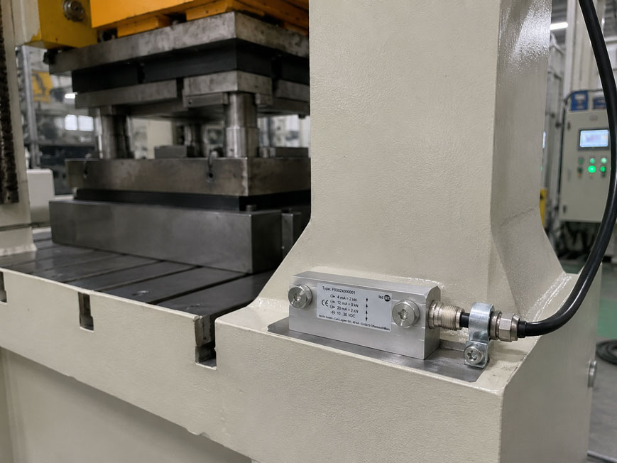
A strain transducer makes it possible to retrofit force measurement to existing machines, presses, steel structures or vessel supports without having to install a conventional load cell directly in the force path.
The sensor is bolted onto a loaded machine component and measures its local strain or compression. After calibration using a known reference load, the actual machine force can be determined from this structural deformation.
This measuring principle is particularly useful when an existing structure should not be cut apart or fundamentally modified mechanically.
However, one point is crucial: The strain transducer does not automatically measure the total machine force. It measures the local deformation precisely at its mounting position. The mounting surface, installation location, bolt preload, structural stiffness, temperature and calibration therefore have a major influence on the quality of the resulting force signal.
A particularly suitable product from the ICS portfolio is the WIKA F9302 strain transducer. It is designed for retrofitting to existing structures, is mounted with two bolts and has an integrated amplifier with a 4–20 mA output.
For applications with several measuring points or a conventional strain-gauge bridge signal, the WIKA F9846 strain transducer is also available.
Further solutions can be found under force, weighing, speed and torque sensors at ICS Schneider.
Table of Contents
- How does a strain transducer work?
- Why is force measurement indirect?
- Relationship between strain, stress and force
- When is retrofitting worthwhile?
- Finding the correct measuring point on the machine
- Avoiding bending and local stress concentrations
- Preparing the mounting surface correctly
- Aligning the sensor with the strain direction
- Bolt preload and frictional connection
- Evaluating the zero signal correctly after installation
- Influence of machine stiffness
- Considering temperature drift correctly
- Why a reference load is required
- Multi-point calibration and linearity
- Checking repeatability of machine loading
- Measuring static and dynamic forces
- 4–20 mA or mV/V?
- Combining several strain transducers
- Practical example: retrofitting press-force measurement
- Typical fault patterns
- Recommended retrofit and calibration procedure
- Suitable strain transducers from ICS Schneider
- Conclusion
- FAQ
How does a strain transducer work?
When a machine component is mechanically loaded, it deforms slightly within its elastic range.
Depending on the direction of loading, this can result in:
- tensile strain,
- compression,
- bending,
- a combination of several types of deformation.
The resulting changes in length are often extremely small and are usually expressed in:
µε
or microstrain.
The following applies:
1 µε = 1 µm/m
Example
A machine strut with an initial length of:
1,000 mm
experiences a strain of:
200 µε
This corresponds to an actual change in length of only:
0.2 mm
A strain transducer detects this very small deformation and converts it into an electrically measurable signal.
Why is force measurement indirect?
A conventional load cell is installed directly in the force path.
The entire force to be measured is deliberately transmitted through its measuring body.
A retrofitted strain transducer works differently.
It is mounted on an existing machine structure and measures its local deformation.
The measured value therefore depends not only on the force
but also, for example, on:
- component geometry,
- material,
- cross-section,
- load path,
- clamping conditions,
- mounting position of the sensor.
Two identical strain transducers mounted at two different positions on the same machine can therefore measure completely different strain values under the same machine force.
Only in combination with the machine component and suitable calibration does the sensor become a force measuring system.
Relationship between strain, stress and force
Within the elastic range of a material, there is fundamentally a relationship between mechanical strain and stress.
For a simple uniaxial load condition, Hooke’s law approximately applies:
σ = E · ε
where:
σ= mechanical stress,E= modulus of elasticity,ε= strain.
For a simple axially loaded structure, the following can also apply:
F = σ · A
and therefore theoretically:
F = E · ε · A
In real machines, however, this relationship is often considerably more complex
Machine frames contain:
- weld seams,
- holes,
- reinforcing ribs,
- changing cross-sections,
- several parallel load paths,
- local bending moments.
A purely mathematical conversion from µε to kN is therefore often not sufficient in practice.
The more reliable method is to calibrate the completely installed measuring system using known reference forces.
When is retrofitting worthwhile?
Strain transducers are particularly useful when existing machines are to be retrofitted with force or load monitoring.
Typical applications include
- press-force monitoring,
- punching and embossing machines,
- injection-moulding machines,
- machine frames,
- vessel supports,
- steel structures,
- construction machinery,
- wind turbines,
- silo weighing and load monitoring.
Advantage compared with a direct load cell
The existing structure often does not need to be cut apart.
The strain transducer can be retrofitted onto a suitable structural surface.
Especially on large machines, this can be considerably simpler and more economical than installing a load cell directly into the main force path afterwards.
Finding the correct measuring point on the machine
Selecting the sensor position is one of the most important steps when retrofitting.
The ideal location is an area in which the required machine force produces sufficiently large and reproducible strain.
Suitable areas have
- a clearly defined load path,
- sufficient elastic deformation,
- as little local bending as possible,
- good mechanical accessibility,
- reproducible loading.
Areas directly next to the following may be unsuitable
- bolt holes,
- weld seams,
- major changes in cross-section,
- reinforcing ribs,
- load application points
.
Local stress concentrations often occur in these areas and may not be representative of the actual machine-force behaviour.
For complex structures
a suitable sensor position can be determined beforehand using:
- finite element analysis,
- temporary strain-gauge measurements,
- measurements at several possible positions.
Avoiding bending and local stress concentrations
A strain transducer should preferably measure deformation that is clearly related to the required machine force.
Additional bending, however, can create different strains on opposite sides of a component.
Example
A support is ideally loaded axially with:
100 kN
.
If the load is applied slightly eccentrically, an additional bending moment is generated.
One side can then experience significantly greater compression than the opposite side.
A single sensor would measure this local combination of axial load and bending.
Possible measures
- mount the sensor closer to a position that is less sensitive to bending,
- use two sensors on opposite sides,
- average the measured values from several sensors,
- improve the mechanical load application.
For particularly demanding applications, a symmetrical multi-sensor arrangement can significantly reduce unwanted bending sensitivity.
Preparing the mounting surface correctly
The strain of the machine component is mechanically transferred to the strain transducer through the contact surfaces and bolted connection.
A poor mounting surface therefore has a direct effect on measurement quality.
The surface should be
- flat,
- clean,
- mechanically sound metal,
- free of paint, rust and dirt,
- free of burrs
.
For the WIKA F9302, the minimum requirement for mounting-surface flatness is:
0.05 mm
and the surface roughness is:
Rz = 16
.
Paint between the sensor and the machine is problematic
A coating can:
- settle,
- creep,
- move under changing loads.
This can change the mechanical transfer between the machine and the sensor.
The mounting surface is therefore a functional part of the measuring chain.
Aligning the sensor with the strain direction
The sensor should be installed so that its sensitive measuring direction is aligned as closely as possible with the relevant strain direction of the machine structure.
On an axially loaded support
the measuring axis should, for example, run parallel to the force or strain direction.
Incorrect rotational alignment can
- reduce the usable signal range,
- increase transverse or bending influences,
- make calibration more difficult.
The required orientation should therefore be clearly defined and documented before drilling the mounting threads.
Bolt preload and frictional connection
The deformation of the machine structure must be transferred reliably to the sensor.
For this purpose, the strain transducer is frictionally connected to the component.
The mounting bolts generate the required contact pressure between the sensor and the machine surface.
Insufficient bolt preload
can result in:
- micro-movements,
- slippage,
- hysteresis,
- poor repeatability.
Uneven tightening
can mechanically influence the sensor during installation and cause an unnecessarily large zero-point offset.
On the WIKA F9302, the two M6 mounting bolts are tightened evenly to:
12 Nm
.
If the sensor is installed repeatedly, the same mechanical procedure should be used each time. Different installation conditions can result in a different zero signal or changed sensitivity.
Evaluating the zero signal correctly after installation
After mechanical installation, the sensor output signal may already differ from its unloaded initial state.
Possible causes include:
- mounting preload,
- residual stress in the machine component,
- uneven tightening,
- an existing machine load,
- temperature conditions.
A defined mechanical zero condition must therefore be established
This can, for example, mean:
- machine ready for operation but without process force,
- tool installed but unloaded,
- defined temperature after warm-up.
Only under these conditions should the electrical zero point or subsequent force scaling be established.
A zero point without a clearly defined machine condition is only reproducible to a limited extent.
Influence of machine stiffness
The strain transducer uses the elastic deformation of the machine as its measuring body.
If the structural stiffness changes, the relationship between force and sensor signal can also change.
Influencing factors include, for example
- tool changes,
- modified bolted joints,
- additional braces,
- repair welds,
- changes to machine mounting,
- play in guides or joints.
The force calibration should therefore be checked whenever the mechanical structure in the relevant force path has been changed.
Considering temperature drift correctly
Temperature is particularly important for indirect force measurement because not only the sensor itself but also the machine structure behaves differently depending on temperature.
The sensor can show temperature-related changes in
- zero signal,
- rated output or sensitivity.
The WIKA F9302 incorporates a temperature-compensated Wheatstone bridge circuit.
For the sensor, the following temperature influences are specified, among others:
Zero signal: 0.1% / 10 K
and:
Rated output: 0.3% / 10 K
However, the machine itself also changes
Temperature changes can:
- cause thermal expansion,
- change preloads within the structure,
- influence contact conditions,
- change the force distribution within the machine.
A temperature-compensated sensor cannot completely compensate for these actual mechanical changes in the machine.
For high accuracy requirements, calibration should therefore be carried out at representative operating temperatures wherever possible, and the machine temperature may also need to be measured.
Why a reference load is required
After installation, the strain transducer initially provides a signal representing the local structural strain.
To determine a machine force in:
kN
a known reference load is required.
Example
A press is loaded using a suitable reference load cell.
At:
0 kN
the output is:
4.00 mA
.
At:
500 kN
the output is:
16.10 mA
.
At:
650 kN
the output reaches:
20.00 mA
.
From these reference points, the force characteristic of the complete combination of:
- machine structure,
- mounting position,
- strain transducer,
- measuring amplifier
can be determined.
For this exact installation, the sensor then performs the function of a load cell.
Multi-point calibration and linearity
A simple two-point adjustment at 0% and 100% is not always sufficient to fully evaluate the behaviour of a real machine structure.
A multi-point test is therefore recommended.
For example at
- 0%,
- 25%,
- 50%,
- 75%,
- 100%
of the intended machine load.
This makes it possible to identify
- non-linearity,
- changes in the load path,
- mechanical play,
- settling effects,
- hysteresis.
If necessary, the test should be carried out with both increasing and decreasing force.
Checking repeatability of machine loading
A single correct measuring point is not sufficient if the same reference load produces a different sensor signal every time it is repeated.
Example
| Load | Measurement 1 | Measurement 2 | Measurement 3 |
|---|---|---|---|
| 300 kN | 11.42 mA | 11.39 mA | 11.41 mA |
These values indicate good repeatability.
Significantly greater fluctuations can indicate
- moving contact points,
- slippage at the sensor mounting,
- changing load paths,
- play in the machine,
- temperature-dependent structural changes.
The mechanical cause should therefore be investigated before making an electronic correction.
Measuring static and dynamic forces
Depending on the version, strain transducers can be used for both static and dynamic measuring tasks.
For the F9302, a cut-off frequency of:
< 2 kHz (-3 dB)
is specified.
This allows, for example, the measurement of
- press-force curves,
- punching operations,
- load peaks,
- recurring machine cycles.
The actual usable dynamics of the overall system additionally depend on:
- machine structure,
- signal conditioning,
- data acquisition,
- filter settings.
4–20 mA or mV/V?
Different sensor concepts are available depending on the application.
Integrated 4–20 mA amplifier
The WIKA F9302 has an integrated amplifier and provides:
4 … 20 mA
in a 3-wire configuration.
This is particularly practical for:
- PLC connection,
- long cable runs,
- industrial machine control systems,
- retrofit applications without a separate strain-gauge amplifier.
Direct mV/V bridge signal
The WIKA F9846, on the other hand, operates with a strain-gauge bridge signal with a nominal rated output of:
1.0 ±0.15 mV/V
.
This signal requires a suitable measuring amplifier or corresponding evaluation unit.
This can be particularly useful when several sensors are to be evaluated together or when special measuring amplifiers are used.
Combining several strain transducers
Large machines often have several parallel load paths.
A single sensor may therefore only measure the load in one part of the structure.
Example
A press has four vertical columns.
A sensor mounted on only one column measures the strain occurring there.
With asymmetric tool loading, however, the force is not necessarily distributed equally across all four columns.
A multi-sensor solution can therefore offer advantages
With sensors at several structurally comparable positions, it is possible to:
- estimate total loads more reliably,
- detect asymmetric loading,
- reduce bending influences,
- monitor load distribution.
The mathematical combination of the individual signals must be determined during calibration.
Practical example: retrofitting press-force measurement
On an existing hydraulic press, the actual press force is to be monitored during every production cycle in future.
A direct load cell cannot be installed without major structural modifications.
1. Determine a suitable measuring point
The side frames of the press undergo elastic elongation under load.
Measurements show that a central area of the frame has sufficiently large and reproducible longitudinal strain.
2. Prepare the mounting surface
The mounting position is:
- stripped of paint,
- prepared flat,
- cleaned.
The threaded holes are produced precisely according to the sensor geometry.
3. Mount the strain transducer
The sensor is aligned with the main strain direction and evenly secured using the specified M6 bolts.
The connection cable is mechanically strain-relieved and must not mechanically load the sensor.
4. Bring the machine into a defined zero condition
The tool and normal machine components remain installed, but no press force is applied.
This condition is defined as:
0 kN
.
5. Apply a reference force
Several known forces are generated using a suitable reference force measuring system:
100 kN
250 kN
400 kN
500 kN
6. Determine the characteristic curve
The strain transducer output signal is stored for each reference force.
The resulting characteristic curve is stored in the PLC.
7. Repeatability test
The load sequence is repeated several times.
The measuring point is only approved for production operation once the zero point, slope and repeatability are sufficiently stable.
8. Consider temperature
The press heats up significantly during a shift.
It is therefore additionally checked whether the same reference force produces sufficiently comparable measured values when the machine is cold and warm.
This example shows the essential difference compared with a directly calibrated load cell: The machine structure itself becomes the measuring body and is therefore part of the calibration.
Typical fault patterns
| Observation | Possible cause | Recommended check |
|---|---|---|
| Measured value not reproducible after installation | different bolt preload | check mounting and tightening torque |
| Signal jumps during load changes | slippage between sensor and mounting surface | check surface and bolted connection |
| Large zero-point offset immediately after installation | mounting stress or uneven surface | check surface and even tightening |
| Force indication changes with machine temperature | sensor and structural temperature influence the measurement | record temperature and check the warm condition |
| Measurement is correct at low load but not at high load | non-linearity of the machine load path | perform multi-point calibration |
| Different values with increasing and decreasing load | mechanical hysteresis or play | compare loading and unloading sequence |
| Measured value reacts strongly to lateral load | bending influence at the sensor position | check a different position or multiple sensors |
| Measured value changes after tool replacement | load path or structural stiffness has changed | verify calibration again |
| Measurement slowly drifts | settling at the mounting surface or machine | observe mounting and zero point over time |
| Signal is noisy | EMC interference or poor cable routing | check cable, shielding and routing |
| One sensor indicates a different load than the opposite sensor | asymmetric machine loading | check load distribution and tool alignment |
| Calibration is no longer correct after repair welding | structural stiffness or residual stress has changed | recalibrate the measuring system |
Recommended retrofit and calibration procedure
- Define the measuring task: Determine which machine force or load is to be monitored.
- Determine maximum load: Consider normal operation, overload and dynamic peaks.
- Analyse the load path: Determine which machine components transmit the relevant force.
- Find a suitable measuring point: Select reproducible axial strain with as little bending influence as possible.
- Estimate the expected strain: Select a sensor range suitable for the machine structure.
- Define the mounting direction: Align the measuring axis with the relevant strain direction.
- Prepare the mounting surface: Remove paint, rust, burrs and unevenness.
- Machine the holes accurately: Do not mechanically stress the sensor through incorrect hole spacing.
- Mount the sensor evenly: Observe the specified bolt tightening torque.
- Provide cable strain relief: Do not introduce mechanical forces into the sensor through the connection cable.
- Check the electrical supply: Verify the output signal and measuring chain.
- Establish a defined zero condition: Clearly document the machine condition.
- Store the zero signal: Only after complete installation and mechanical stabilisation.
- Apply a reference force: Use a suitable and traceable force measuring system.
- Check several load points: Do not measure only the zero and full-scale points.
- Reduce the load again: Check hysteresis.
- Repeat the measuring sequence: Evaluate repeatability.
- Create the force characteristic curve: Convert the sensor signal into machine force.
- Document the temperature condition: Record the calibration conditions.
- Check the warm condition: Carry out a comparison measurement if machine heating is relevant.
- Define limit values: Set overload and plausibility limits.
- Document the calibration: Record mounting position, bolts, load points and characteristic curve.
- Check again after mechanical changes: Especially after welding, tool or structural modifications.
Suitable strain transducers from ICS Schneider
WIKA F9302 – retrofit strain transducer with integrated amplifier
The WIKA F9302 is specifically designed for measuring deformation on existing solid structural components.
Typical applications include:
- injection-moulding machines,
- presses,
- punching and embossing machines,
- steel structures,
- vessel supports,
- wind turbines,
- construction machinery.
Important features include:
- Strain measuring ranges: 0 … ±200 µε, 0 … ±500 µε and 0 … ±1,000 µε,
- relative linearity deviation: ≤ ±2% Fnom,
- output signal: 4 … 20 mA, 3-wire,
- power supply: 10 … 36 V DC,
- degree of protection: IP67,
- cut-off frequency: < 2 kHz,
- integrated digitally programmable amplifier,
- suitable for static and dynamic measurements.
Two M6 bolts are used for mounting. The specified tightening torque is:
12 Nm
The design with integrated amplifier is particularly suitable for retrofit projects in which the signal is to be transmitted directly to an industrial PLC or evaluation unit.
WIKA F9846 – standard strain transducer with strain-gauge signal
The WIKA F9846 is also designed for retrofitting to existing structures.
Important features include:
- measuring ranges from 0 … ±200 µε to 0 … ±1,000 µε,
- total error ≤ ±1% Fnom,
- mV/V strain-gauge bridge signal,
- simple bolt mounting,
- applications including silo weighing, presses, steel structures and vessel supports.
The F9846 can be particularly useful when several strain transducers are to be evaluated together using a separate evaluation unit.
Further solutions can be found under force, weighing, speed and torque sensors at ICS Schneider.
Conclusion
Strain transducers are a particularly useful way of retrofitting existing machines with force or load measurement.
The machine structure itself becomes the measuring body
The sensor measures the local elastic deformation of the existing component rather than the total machine force directly.
The sensor position determines the signal
The measuring point should provide sufficiently large and reproducible strain with as little influence from bending and interfering forces as possible.
The mounting surface is part of the measuring chain
Uneven surfaces, coatings or poor bolted connections can influence the mechanical transfer and therefore the measurement result.
Bolt preload must be reproducible
Only a stable frictional connection between the machine and sensor enables reproducible transfer of the strain.
Temperature influences both the sensor and the machine
Even with a temperature-compensated sensor, thermal deformation of the machine structure can be measured as actual strain.
A reference load is essential for force scaling
Only calibration of the complete combination of machine, sensor position and evaluation electronics enables reliable conversion of the strain signal into kN.
The system must be checked again after mechanical changes
Tool changes, modifications, welding work or changed load paths can influence the existing force characteristic curve.
For practical applications
Analyse the load path → determine a suitable strain measurement point → minimise bending influence → prepare a flat and clean mounting surface → align the sensor correctly → tighten the bolts reproducibly → provide cable strain relief → establish a defined zero condition → apply several known reference forces → determine the characteristic curve → compare loading and unloading → check temperature behaviour → document calibration → verify again after mechanical modifications.
FAQ: Retrofitting Strain Transducers to Machines
What is a strain transducer?
A strain transducer measures the very small elastic elongation or compression of a component and converts it into an electrical measuring signal.
Does a strain transducer measure force directly?
No. It first measures the local structural deformation. The associated force is then determined by calibrating the complete installation.
Why is a strain transducer suitable for retrofitting?
Because it can be bolted onto an existing machine component, meaning that a conventional load cell often does not need to be installed directly in the force path.
Where should the sensor be mounted?
At a location with sufficiently large and reproducible strain that is as clearly related as possible to the required machine force.
Why should the sensor not be mounted directly next to a weld seam?
Local stress concentrations and residual stresses can occur there and may not be representative of the required machine force.
Why is bending problematic?
Bending creates different strains on different sides of a component and can therefore strongly influence the signal from a single sensor.
How can the influence of bending be reduced?
By selecting a suitable mounting position or by using several symmetrically arranged sensors whose signals are evaluated accordingly.
Does the mounting surface need to be machined?
Yes. It should be flat, clean, mechanically sound and free of paint, rust and burrs.
What mounting-surface requirements apply to the F9302?
A minimum flatness of 0.05 mm and a surface roughness of Rz = 16 are specified.
Why must paint be removed beneath the sensor?
A coating can settle or move under load and thereby change the transfer of component strain to the sensor.
How is the WIKA F9302 mounted?
It is secured to the machine structure using two M6 bolts.
What tightening torque applies to the F9302?
A tightening torque of 12 Nm is specified for the M6 mounting bolts.
Why is the tightening torque important?
The bolted connection creates the frictional connection between the machine component and sensor. Different mounting conditions can influence strain transfer and the zero point.
What does µε mean?
µε stands for microstrain. 1 µε corresponds to a relative change in length of 1 µm per metre.
Which measuring ranges are available for the F9302?
Typical measuring ranges extend from 0 … ±200 µε to 0 … ±1,000 µε.
What output signal does the F9302 provide?
The sensor has an integrated amplifier and provides a 4–20 mA signal in a 3-wire configuration.
Can the signal be connected directly to a PLC?
A suitable PLC or data-acquisition 4–20 mA input can be used for evaluation, provided the power supply and connection are implemented in accordance with the device specifications.
Why must the sensor be calibrated after installation?
Because the relationship between local strain and total machine force depends on the specific machine structure and sensor position.
How is calibration carried out?
Known reference forces are applied to the machine and the corresponding sensor signals are stored. The force characteristic curve is determined from these values.
Is calibration at a single load point sufficient?
For reliable evaluation, several load points are useful in order to check linearity, repeatability and hysteresis.
Why should unloading also be measured?
This makes it possible to determine whether different measured values occur at the same force during loading and unloading.
Can machine temperature influence the measurement?
Yes. In addition to the temperature dependence of the sensor, the machine structure itself can undergo thermal deformation.
Is the F9302 temperature-compensated?
Yes. A temperature-compensated Wheatstone bridge circuit is used in the sensor.
Can temperature compensation eliminate all temperature influences?
No. It can reduce sensor-related errors, but it cannot completely compensate for actual thermal deformation or changes in the load path within the machine.
Can a strain transducer measure dynamic forces?
Yes. The F9302 is designed for static and dynamic measuring tasks and has a cut-off frequency of less than 2 kHz at -3 dB.
What happens after the machine is modified?
If the load path or structural stiffness changes, the existing force calibration should be verified again.
Can several strain transducers be used simultaneously?
Yes. This can be useful where several load paths exist or where bending influences need to be reduced.
What is the difference between the F9302 and F9846?
The F9302 has an integrated amplifier with an industrial 4–20 mA output. The F9846 provides a conventional strain-gauge bridge signal and is used with a suitable external evaluation unit.
Which strain transducer is particularly suitable for retrofitting to machines?
The WIKA F9302 was specifically developed for retrofitting to existing solid structures.
Where can I find further force and strain sensors?
Further solutions can be found under force, weighing, speed and torque sensors at ICS Schneider.