


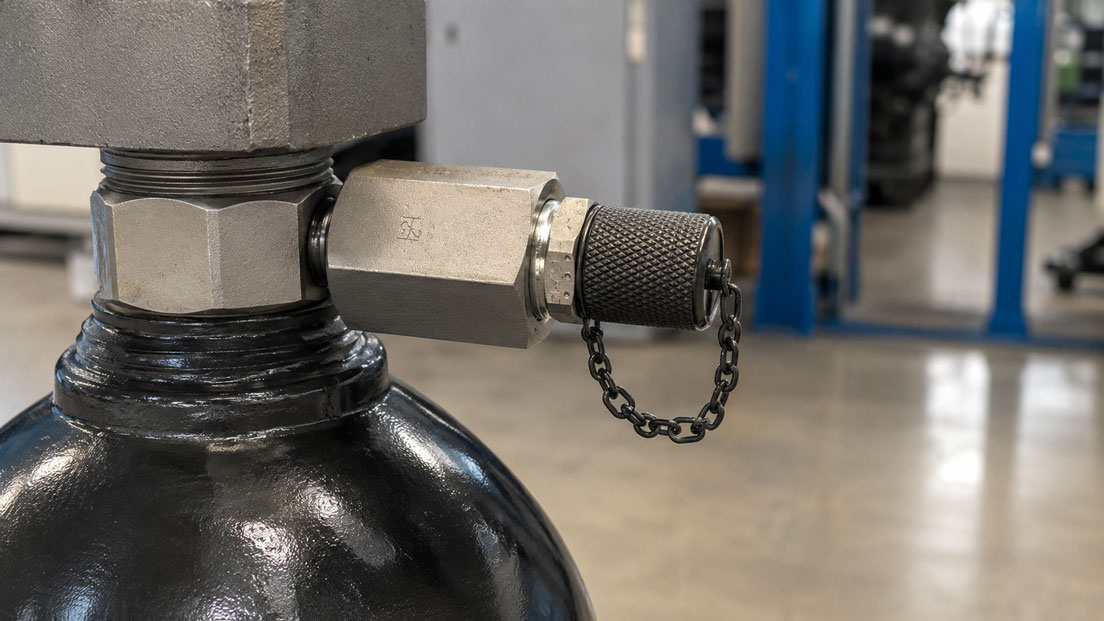
Hydropneumatic accumulators perform important functions in hydraulic systems. They store energy, compensate for leakage and volume flows, damp pressure peaks and pulsations, or provide a short-term hydraulic reserve in the event of pump failure. To perform these functions correctly, the gas chamber must be charged with the correct nitrogen pre-charge pressure.
If the pre-charge pressure is too low, the usable accumulator volume is reduced and, in a bladder accumulator, the bladder may be damaged at the oil valve. If the pre-charge pressure is too high, however, insufficient hydraulic fluid can enter the accumulator. The accumulator is then filled with gas but can perform its intended hydraulic function only to a limited extent or not at all.
Checking and topping up the pressure may appear straightforward at first: connect a pressure gauge, open the nitrogen cylinder and set the required pressure. In reality, however, this involves working on pressure equipment containing stored energy. The gas charging valve, accumulator adapter, test hose, pressure regulator and pressure gauge must be compatible, and the hydraulic side must be safely depressurised before the pre-charge pressure is measured.
Suitable components can be found in the MINIMESS gas charging valves and accessories category. Further measuring couplings, microbore hoses, adapters and service connections are grouped together in the MINIMESS couplings and hoses section.
Contents
- How does a hydraulic accumulator work?
- What does gas pre-charge pressure mean?
- Why only nitrogen may be used
- Why compressed air and oxygen are unsuitable
- Safely depressurising the hydraulic accumulator before testing
- Which equipment is required?
- Selecting the gas charging valve and accumulator adapter
- Why a pressure regulator is required
- Selecting the correct test and charging hose
- Using a suitable pressure gauge range
- Checking the gas pre-charge pressure correctly
- Charging the hydraulic accumulator with nitrogen in a controlled manner
- Considering temperature and pre-charge pressure
- Detecting leaks and gradual pressure loss
- Typical mistakes when checking and charging
- Documenting test results
- Practical example: Bladder accumulator in a mobile machine
- Selection guide for charging and testing equipment
- Which products are suitable?
- Conclusion
- Frequently asked questions
How does a hydraulic accumulator work?
A hydraulic accumulator contains a gas chamber and a fluid chamber. Depending on the design, these two chambers are separated by an elastic bladder, a diaphragm or a moving piston. The gas side contains compressed nitrogen, while the fluid side contains the hydraulic medium.
When the hydraulic pressure rises above the gas pre-charge pressure, hydraulic fluid flows into the accumulator. The gas is compressed and absorbs energy. When the system pressure subsequently falls, the nitrogen expands and forces the stored fluid back into the hydraulic system.
Correct operation depends largely on the proper relationship between the gas pre-charge pressure, minimum operating pressure, maximum operating pressure and accumulator volume. The pre-charge pressure is therefore not an arbitrary setting. It is calculated for the specific function of the accumulator or specified by the system or accumulator manufacturer.
| Accumulator function | Effect of the gas chamber | Consequence of an incorrect pre-charge pressure |
|---|---|---|
| Energy storage | Hydraulic energy is stored by compressing the nitrogen | Insufficient usable fluid volume or inadequate energy reserve |
| Pulsation damping | The gas cushion absorbs rapid pressure fluctuations | Poor damping or excessive load on the separating element |
| Leakage compensation | Small quantities of fluid are supplied when the pressure falls | System pressure falls too soon or the accumulator does not respond as intended |
| Emergency function | Stored fluid continues to supply a consumer for a short period | The required reserve is not fully available |
What does gas pre-charge pressure mean?
The gas pre-charge pressure is the pressure on the nitrogen side when the hydraulic side of the accumulator has been safely depressurised. It is frequently designated as p0. This condition must not be confused with the gas pressure during normal system operation.
As soon as hydraulic fluid enters the accumulator, the nitrogen is compressed. The gas pressure then rises together with the hydraulic pressure. A gas pressure indicated while the system is operating is therefore not automatically the pre-charge pressure.
For a reliable pre-charge pressure test, the accumulator must be isolated from the hydraulic system and the fluid side must be fully relieved to the specified depressurised condition. If residual hydraulic pressure remains at the accumulator, the pressure gauge will indicate an excessively high gas pressure.
The required pre-charge pressure depends on the accumulator design and its function. An accumulator used for pulsation damping is sized differently from one used for energy supply or leakage compensation. Universal percentage values should therefore not be applied to a specific system without verification.
Why only nitrogen may be used
Suitable dry nitrogen is used for hydraulic accumulators. Under normal operating conditions, nitrogen is inert and does not form a combustible mixture with hydraulic oil. It is also available in compressed-gas cylinders in defined quality grades and at high charging pressures.
The required nitrogen quality depends on the accumulator manufacturer’s specifications. Contamination, moisture or unsuitable gases can impair seals, the bladder, the diaphragm and the gas valve. The gas cylinder must be clearly identified and approved for the intended application.
A nitrogen cylinder must not be connected directly and without regulation to the accumulator. The cylinder pressure may be considerably higher than the permissible gas pressure of the accumulator, pressure gauge or charging hose. A suitable pressure regulator must therefore be installed between the compressed-gas cylinder and the charging unit.
Why compressed air and oxygen are unsuitable
Workshop compressed air must not be used to pre-charge a hydraulic accumulator. It contains oxygen and, depending on its treatment, may additionally introduce moisture, oil mist and particles. Under high pressure and in combination with oil, this can cause dangerous reactions.
Pure oxygen is particularly dangerous. Oxygen can react violently with oil, grease and other organic substances. Even small amounts of contamination on valves, threads or hoses can create a significant fire or explosion hazard under high pressure.
The fact that air consists mainly of nitrogen does not make compressed air a suitable substitute. The oxygen content remains present, and neither the composition nor the purity is controlled for the safe charging of hydraulic accumulators.
If an accumulator has accidentally been filled with air, oxygen or an unknown gas, it should not simply remain in operation or be “corrected” by adding nitrogen. The further procedure must be determined by qualified personnel in accordance with the accumulator manufacturer’s instructions.
Safely depressurising the hydraulic accumulator before testing
A hydraulic accumulator may contain considerable energy even when the machine has been switched off. Switching off the hydraulic power unit therefore does not automatically mean that the accumulator is depressurised. Check valves, shut-off valves or closed control edges can trap pressure for long periods.
Before work is performed on the gas side, the accumulator must be isolated in accordance with the operating instructions and the hydraulic side must be depressurised in a controlled manner. This may involve a designated accumulator safety and shut-off block. The actual absence of hydraulic pressure must be verified at a suitable measuring point.
Important safety measures include:
- Allow only trained and qualified personnel to carry out the work.
- Secure the machine against unintended restarting.
- Isolate the accumulator from the hydraulic system and depressurise the fluid side in a controlled manner.
- Confirm the absence of hydraulic pressure using a suitable measuring instrument.
- Secure the gas cylinder in an upright position and protect it against falling, heating and damage.
- Use only undamaged charging and testing components suitable for the pressure involved.
- Do not stand in line with the hose, coupling, valve or pressure gauge.
- Use nitrogen only in adequately ventilated areas.
- Never remove the gas charging valve or accumulator housing while it is under pressure.
The nitrogen chamber remains pressurised during the pre-charge pressure test. “Hydraulically depressurised” therefore does not mean that the complete accumulator can be opened safely.
Which equipment is required?
Coordinated equipment is required for controlled pre-charge pressure testing and charging. The exact configuration depends on the gas valve, accumulator design, pre-charge pressure and cylinder connection.
| Component | Function | What must be considered? |
|---|---|---|
| Gas charging valve | Permanent access to the gas side of the accumulator | Thread, sealing principle, pressure rating and accumulator approval |
| Accumulator adapter | Connection between the gas valve and accumulator port | Suitable accumulator design and gas-tight connection |
| Charging and testing unit | Opening the gas valve, indicating pressure, charging and relieving pressure | Valve type, pressure gauge range and permissible pressure |
| Pressure regulator | Reduction of the high cylinder pressure | Inlet and outlet pressure, nitrogen suitability and control range |
| Charging hose | Connection between the pressure regulator and testing unit | Pressure rating, gas tightness, length, condition and connections |
| Pressure gauge | Indication of the gas pre-charge pressure | Measuring range, accuracy, readability and overload resistance |
| Relief valve | Controlled depressurisation of the charging line | Safe discharge and unambiguous operation |
The permissible pressure of the complete charging assembly is always limited by its weakest component. A gas charging valve rated for 400 bar does not automatically make a hose or pressure gauge with a lower pressure rating suitable for high pressure.
Selecting the gas charging valve and accumulator adapter
The gas charging valve provides service access to the nitrogen chamber. When the matching coupling or charging unit is connected, the valve mechanism is opened in a controlled manner. After disconnection, the valve closes again and limits gas loss.
Gas charging valves for hydraulic accumulators must provide a high level of gas tightness. A connection that appears externally leak-tight with hydraulic oil may still allow measurable nitrogen leakage. Valves, seals and couplings specifically suitable for gas should therefore be used.
The MINIMESS® 1615 gas charging valve with accumulator adapter is intended for installation on commonly used bladder accumulators. Before selection, however, the connection thread, valve design, accumulator manufacturer and permissible pressure must be checked.
Adapters must not be selected solely on the basis that the thread appears to screw in. The thread profile, pitch, sealing surface and valve actuation depth must match. An incorrect adapter may leak, damage the valve or open the valve pin in an uncontrolled manner.
Why a pressure regulator is required
A nitrogen cylinder contains gas at high pressure. If it is connected directly to a hydraulic accumulator without suitable pressure regulation, the accumulator pressure can rise very quickly. Briefly opening the cylinder valve may already be sufficient to overcharge a small accumulator.
The pressure regulator reduces the cylinder pressure to a controllable outlet pressure. Its outlet range should match the intended pre-charge pressure. A regulator with a very large outlet range is often more difficult to adjust precisely at low pre-charge pressures than a suitably sized model.
The permissible outlet pressure of the pressure regulator must not exceed the pressure limits of the downstream components. Charging must be carried out slowly. This reduces severe temperature changes, rapid pressure increases and mechanical loading of the bladder or diaphragm.
The gas charging and testing unit with pressure regulator combines pressure reduction with components for setting and monitoring the gas pressure in nitrogen-charged hydraulic accumulators.
Selecting the correct test and charging hose
The charging hose is subjected to nitrogen pressure during filling and must be rated for at least the maximum possible outlet pressure of the pressure regulator. The decisive value is not only the required accumulator pre-charge pressure, but also a possible operating or regulator fault.
Before each use, the hose should be checked for abrasion, kinks, crushed areas, damaged fittings and ageing. A damaged gas hose must not remain in use. Under pressure, a hose can move uncontrollably and cause injury.
The hose should be long enough to provide a safe working distance, but should not be unnecessarily long. A longer hose contains more compressed gas and increases the volume that must be depressurised in a controlled manner after the gas cylinder has been closed.
The hose must be routed so that it cannot be kinked, driven over, trapped or damaged by hot components or moving machine parts. Couplings and fittings must not be subjected to tensile or bending loads.
Using a suitable pressure gauge range
The pressure gauge on the charging and testing unit must be suitable for the expected pre-charge pressure. An excessively large measuring range makes precise adjustment more difficult. A measuring range that is too small may be overloaded or damaged during charging.
For a pre-charge pressure of 15 bar, for example, a pressure gauge with a range up to 400 bar is unsuitable if precise adjustment is required. Its display resolution would be too low in the relevant range. Conversely, a 25-bar pressure gauge must not be used if the pressure regulator can supply a considerably higher outlet pressure.
For varying accumulator pressures, interchangeable pressure gauges or different charging and testing sets may be useful. The measuring range, accuracy class, overload resistance and calibration status should be documented.
Checking the gas pre-charge pressure correctly
The exact operating sequence depends on the accumulator, gas valve and charging unit. The operating instructions for the components used are therefore decisive. A typical safe testing procedure can nevertheless be summarised as follows:
- Switch off the system and secure it against restarting.
- Isolate the hydraulic accumulator from the system.
- Slowly and controllably relieve the fluid side to the specified depressurised condition.
- Verify the absence of pressure on the hydraulic side.
- Remove the protective cap from the gas valve and inspect the connection for damage or contamination.
- Connect the suitable charging and testing unit while it is depressurised.
- Close the relief valve on the testing unit.
- Slowly open or actuate the gas valve in accordance with the operating instructions.
- Wait for the indication to stabilise briefly and read the value.
- Document the measured value together with the accumulator and ambient temperature.
- Close the gas valve again.
- Relieve the pressure trapped in the testing unit in a controlled manner through the relief valve.
- Disconnect the testing unit only after it has been fully depressurised.
- Check the gas valve for leaks and refit the protective cap.
When the testing unit is connected, a small quantity of nitrogen flows from the accumulator into the hose, fitting and pressure gauge. With small accumulators, this additional test volume may noticeably reduce the indicated pre-charge pressure. Repeated testing without topping up can therefore itself cause a pressure loss.
Charging the hydraulic accumulator with nitrogen in a controlled manner
If the measured pre-charge pressure is below the specified target value, the charging unit is additionally connected to the nitrogen cylinder using a suitable hose and pressure regulator. All valves should initially be placed in the starting position specified in the operating instructions.
The nitrogen cylinder is secured and the cylinder valve is opened slowly. The outlet pressure on the pressure regulator is then increased carefully. The accumulator must not be subjected suddenly to the full cylinder pressure.
For a new or completely discharged bladder accumulator, particularly slow pre-charging may be required so that the bladder rests against the accumulator housing in a controlled manner. The precise procedure depends on the accumulator design and manufacturer’s instructions.
The charging procedure is initially stopped slightly below the required final value. After the gas supply has been closed, the pressure should be allowed to stabilise. Expansion and cooling of the previously compressed gas may cause the indication to fall after a short period.
The pressure is then adjusted in small increments if necessary. Once the target value has been reached, the gas cylinder and gas valve are closed. The pressure in the charging hose and testing unit must then be fully relieved through the designated relief valve before any connection is loosened.
An excessively high pre-charge pressure must not be reduced by loosening a fitting in an uncontrolled manner. The gas must be released slowly and safely through the designated relief valve.
Considering temperature and pre-charge pressure
The gas pressure in a hydraulic accumulator is temperature-dependent. When nitrogen is compressed during rapid charging, it heats up. The pressure gauge may therefore initially indicate a higher pressure immediately after charging. When the accumulator subsequently cools to ambient temperature, the pressure falls.
Different temperatures during maintenance can also result in apparent pressure losses. An accumulator tested in a warm workshop will indicate a different pressure on a cold mobile machine even if no leakage has occurred.
For comparable results, pre-charge pressure tests should be performed at a stable and documented temperature wherever possible. If target values are referenced to a specified temperature, the temperature correction prescribed by the accumulator manufacturer must be used.
A simple conversion that does not take account of the accumulator condition, gas volume and absolute pressure may produce incorrect results. Where temperature differences are significant, the manufacturer’s specified correction method should therefore be used rather than relying solely on the pressure-gauge value.
Detecting leaks and gradual pressure loss
A small loss of nitrogen over a long period cannot be completely avoided with many accumulator designs. Gas may permeate through elastomers or escape through aged seals and valves. Regular pre-charge pressure testing is therefore part of preventive maintenance.
An unusually rapid pressure loss may indicate the following causes:
- leaking gas charging valve,
- damaged valve seal,
- valve component not tightened correctly,
- leaking adapter or coupling connection,
- damaged bladder or diaphragm,
- worn piston seals,
- mechanical damage to the accumulator housing,
- incorrect measurement caused by different temperatures.
A leak test should be carried out using a method suitable for the application and approved by the manufacturer. Open flames or unsuitable liquids must of course not be used.
If the pre-charge pressure falls rapidly again after charging, nitrogen should not simply be topped up repeatedly. The cause must be identified and the accumulator taken out of service if necessary.
Typical mistakes when checking and charging
| Mistake | Possible consequence | Correct procedure |
|---|---|---|
| Measuring the pre-charge pressure while the accumulator is hydraulically loaded | The indicated pressure is higher than the actual pre-charge pressure | Isolate the accumulator and fully depressurise the fluid side |
| Using compressed air instead of nitrogen | Risk of fire, explosion, moisture and corrosion | Use only suitable dry nitrogen |
| Connecting the nitrogen cylinder without a pressure regulator | Uncontrolled pressure rise and possible overloading | Use a suitable nitrogen pressure regulator |
| Using the wrong accumulator adapter | Leakage or damage to the gas valve | Verify the thread, sealing principle and valve design unambiguously |
| Pressure gauge range too large | The pre-charge pressure cannot be adjusted accurately enough | Select a measuring range suitable for the target value |
| Unscrewing the hose while it is pressurised | Hose whip and uncontrolled gas release | Fully depressurise the charging line before disconnecting it |
| Reading the pre-charge pressure immediately after rapid charging | Excessively high value caused by heated nitrogen | Allow time for stabilisation and temperature equalisation |
| Changing the pre-charge pressure without documentation | Subsequent diagnosis and comparability are lost | Record the target value, actual value, temperature and action taken |
Documenting test results
A documented pre-charge pressure test makes it easier to assess whether an accumulator is ageing normally or losing an unusual amount of gas. A single measured value is less informative than a sequence of comparable tests.
The test report should contain at least:
- machine, system and accumulator identification,
- accumulator manufacturer, type and serial number,
- accumulator design and nominal volume,
- specified gas pre-charge pressure,
- measured pre-charge pressure before topping up,
- adjusted pre-charge pressure after topping up,
- ambient or accumulator temperature,
- pressure gauge used and measuring range,
- charging and testing unit used,
- leak test performed,
- name of the technician and test date,
- next scheduled test date.
If the history shows an increasingly rapid pressure loss, the test interval should not simply be shortened. It should also be determined whether the gas valve, separating element or seals require repair.
Practical example: Bladder accumulator in a mobile machine
After a prolonged shutdown, severe pressure surges occur in a mobile machine. At the same time, one hydraulic function responds with a delay. The installed bladder accumulator is intended to damp pressure peaks and provide hydraulic oil for a short period.
The machine is first shut down safely and secured against restarting. The accumulator is isolated from the hydraulic system using the existing safety block, and the oil side is depressurised in a controlled manner. A pressure gauge confirms that the hydraulic side is depressurised.
A suitable charging and testing unit is connected to the gas valve. The measured nitrogen pre-charge pressure is considerably below the target value specified in the machine documentation. A minor leak is also detected at the gas valve.
After replacing the designated valve seal, the accumulator is slowly charged with nitrogen through a pressure regulator. Following a stabilisation period, the pre-charge pressure is checked again and adjusted slightly. The charging hose and testing unit are then depressurised in a controlled manner and disconnected.
After recommissioning, the pressure surges are considerably reduced. The pre-charge pressure, temperature, test instrument used and work performed are recorded in the maintenance report. A further test after a shorter interval is intended to confirm that the gas pressure remains stable.
Selection guide for charging and testing equipment
At least the following information should be available when configuring suitable charging and testing equipment:
- manufacturer and type of hydraulic accumulator,
- bladder, diaphragm or piston accumulator,
- gas valve type and connection thread,
- accumulator volume,
- specified nitrogen pre-charge pressure,
- maximum permissible gas and operating pressure,
- temperature range,
- nitrogen-cylinder connection,
- required hose length,
- required pressure gauge range and accuracy,
- single mobile test or regular servicing of several accumulators,
- required adapters for different accumulator manufacturers.
For a service company working with many different accumulators, a configurable test set with several adapters and interchangeable pressure gauges is often more suitable than a single improvised universal connection. Adapter combinations that are not required should be avoided because every additional connection creates a potential leakage path.
Which products are suitable?
The MINIMESS gas charging valves and accessories category includes components for charging, adjusting, testing and controllably depressurising nitrogen-charged hydraulic accumulators.
MINIMESS® 1615 gas charging valve with accumulator adapter
The MINIMESS® 1615 gas charging valve with accumulator adapter provides a permanent gas-tight service connection on commonly used bladder accumulators. The specific version must be selected according to the accumulator connection, pressure and temperature.
MINIMESS® accumulator charging and testing unit
The MINIMESS® accumulator charging and testing unit is intended for recurring testing and charging tasks. Once the nitrogen supply has been closed, the pressure in the unit can be relieved in a controlled manner through the relief valve.
Gas charging and testing unit with pressure regulator
The gas charging and testing unit with pressure regulator combines gas-pressure testing with controlled pressure reduction of the nitrogen supply.
MINIMESS couplings and hoses
Further measuring couplings, hoses and adapters are available in the MINIMESS couplings and hoses section. For gas applications, however, only components whose pressure rating, seals and design are expressly suitable for the intended gas and specific application may be used.
Conclusion: Adjust the nitrogen pre-charge pressure only with suitable equipment
The gas pre-charge pressure is a major factor in determining whether a hydraulic accumulator performs its function reliably. Both an excessively low and an excessively high pre-charge pressure can impair the accumulator volume, damping performance and service life.
For a correct test, the accumulator must be isolated from the hydraulic system and the fluid side safely depressurised. Only then does the measured gas pressure correspond to the actual pre-charge pressure. The energy stored on the nitrogen side nevertheless remains present and requires a controlled working procedure.
Only suitable dry nitrogen may be used for charging. Compressed air and oxygen are not permissible alternatives. A suitable pressure regulator prevents the high cylinder pressure from acting uncontrollably on the accumulator, hose or pressure gauge.
The gas charging valve, accumulator adapter, charging hose, testing unit and pressure gauge must be designed as a complete system. After charging, the trapped hose pressure must be relieved in a controlled manner before any connection is disconnected.
Documenting the target value, actual value, temperature and maintenance action makes it possible to detect gradual gas loss at an early stage. This improves accumulator function and system availability while helping to prevent damage to the bladder, diaphragm or piston.
Frequently asked questions about checking and charging hydraulic accumulators
Which gas is used for hydraulic accumulators?
Suitable dry nitrogen is used in accordance with the accumulator manufacturer’s specifications. Compressed air, oxygen and unknown gas mixtures are not permitted.
Can a hydraulic accumulator be charged using a workshop compressor?
No. Workshop compressed air contains oxygen and may additionally introduce moisture, oil and particles. This creates safety risks and may damage the accumulator.
How is the gas pre-charge pressure measured correctly?
The accumulator is isolated from the hydraulic system and the fluid side is fully relieved to the specified depressurised condition. Only then is the suitable charging and testing unit connected to the gas valve.
Why is the measured pressure lower after charging?
The compressed nitrogen heats up during charging. When it subsequently cools, the pressure falls. In addition, the hose and testing unit fill with gas when connected, which may influence the measured value, particularly with small accumulators.
Can the nitrogen cylinder be connected directly to the accumulator?
No. A suitable pressure regulator is required between the cylinder and accumulator. Otherwise, the high cylinder pressure could overload the accumulator and charging equipment in an uncontrolled manner.
Why must the charging hose be depressurised before disconnection?
Compressed nitrogen remains trapped in the hose and testing unit after the valves have been closed. If a connection is released under pressure, gas may escape suddenly and the hose may move uncontrollably.
How often should the pre-charge pressure be checked?
The test interval depends on the accumulator design, application, operating conditions, manufacturer’s instructions and previous pressure loss. New or repaired accumulators are often initially checked after a shorter interval to confirm gas tightness.
What should be done if the pre-charge pressure falls rapidly again?
The gas valve, seals and separating element should be inspected. Repeatedly topping up the gas without determining the cause is not a permanent solution. If accumulator damage is suspected, the accumulator must be safely taken out of service.
May the gas valve be removed while it is under pressure?
No. The gas valve, accumulator adapter and other pressure-retaining components must not be removed while pressurised. The complete safe depressurisation procedure must follow the accumulator manufacturer’s operating instructions.