


A pressure sensor can indicate different values at 50% of its measuring range depending on whether the test point was approached from zero or from the upper range limit. This difference is typical hysteresis behaviour. It is not visible in a purely ascending calibration and must not be confused with a linearity deviation.
To obtain reliable results, the same pressure points are therefore approached first in the ascending and then in the descending direction. Pressure generation, reference standard, stabilisation, temperature and zero-point handling must remain controlled throughout the entire measurement series. Otherwise, the apparent hysteresis will also include effects caused by drift, leakage, height differences or insufficient settling time.
This article explains how to plan, perform and evaluate ascending and descending series, how hysteresis, linearity and repeatability differ, and which details become crucial when higher accuracy is required.
Table of Contents
- Distinguishing between hysteresis, linearity and repeatability
- Determining measurement deviation at an individual test point
- Calculating hysteresis from ascending and descending values
- Evaluating linearity deviation separately
- Defining test points and measurement series
- Preloading and mechanical history
- Performing ascending and descending series correctly
- Stabilisation and reading time
- Evaluating zero point and zero return
- Controlling temperature during calibration
- Correcting the height difference between reference and device under test
- Accounting for leakage, volume and pressure medium
- Measuring the pressure transmitter output signal correctly
- Evaluation without mixing the error components
- Practical example of an ascending and descending calibration
- Accounting for hysteresis in measurement uncertainty
- Recommended procedure in the laboratory and in field service
- Common errors in ascending and descending series
- Suitable calibration equipment from ICS Schneider
- Conclusion
- FAQ: Hysteresis in pressure calibration
Distinguishing between Hysteresis, Linearity and Repeatability
These terms describe different characteristics of a pressure sensor and must be evaluated separately:
- Measurement deviation: Difference between the indication or output value of the device under test and the corresponding reference value.
- Hysteresis: Difference between the results at the same pressure point under increasing and decreasing pressure.
- Linearity deviation: Deviation of the characteristic curve from a specified reference line, such as a terminal-based line or a best-fit line.
- Repeatability: Scatter observed in repeated measurements under conditions that are as identical as possible and with the same loading direction.
- Zero return: Change in the zero output after the sensor has been loaded up to the upper test point.
A large difference between ascending and descending values is not automatically a linearity error. Conversely, a sensor may have an almost hysteresis-free but noticeably curved characteristic. A single overall error value without a stated calculation method does not reveal these causes.
Determining Measurement Deviation at an Individual Test Point
For a pressure sensor with a digital display, the measurement deviation can be calculated in simplified form as the difference between the DUT indication and the corrected reference pressure:
Measurement deviation = DUT indication − reference pressure
For a pressure transmitter with an electrical output, it must first be specified whether the measured signal will be evaluated directly or converted into a pressure value. For an ideally linear 4…20 mA transmitter, for example:
Ideal signal = 4 mA + 16 mA × (test pressure − lower range value) / measuring span
The signal deviation is then the difference between the measured and ideal output signal. Alternatively, the measured signal is converted into pressure using the specified transfer function. The selected representation must be clearly stated in the test plan and in the result.
The reference pressure is not simply the unprocessed indication of the reference standard. Calibration correction, resolution, stability, head correction and, where applicable, ambient pressure must be taken into account according to the pressure type.
Calculating Hysteresis from Ascending and Descending Values
At each test point, a value from the ascending series is paired with a value from the descending series. The hysteresis difference can be reported with its sign or as an absolute value:
Hysteresis at the test point = descending value − ascending value
Absolute hysteresis = |descending value − ascending value|
It is important that both values correspond to the same reference pressure. If the test points are adjusted according to the indication of the DUT, the actual reference pressures may differ between the ascending and descending directions. In this case, the measured values must be interpolated to common reference points or evaluated using a defined procedure.
The largest absolute hysteresis across the calibrated range can be reported as a characteristic value. However, a point-by-point presentation is more informative for a complete assessment because hysteresis is often not distributed uniformly across the measuring range.
Evaluating Linearity Deviation Separately
Linearity deviation describes the shape of the characteristic curve relative to a defined straight line. The result depends on the selected reference line. Common variants include:
- a straight line through the lower and upper range values,
- a least-squares regression line,
- an independent best-fit straight line,
- a manufacturer-specific characteristic or digital correction function.
Linearity values cannot be compared unambiguously unless the method is stated. The calculation may use the ascending series, the descending series or the mean of both directions. The mean reduces the direction-dependent component but does not eliminate it as a characteristic of the sensor. Hysteresis must therefore still be reported separately or appropriately included in the measurement uncertainty.
Defining Test Points and Measurement Series
The number and position of the test points depend on the measuring range, accuracy target, calibration procedure, instrument specification and intended use. A simple field check may require only a few points, whereas a high-quality laboratory calibration requires more points and possibly several measurement cycles.
EURAMET Calibration Guide No. 17, for example, distinguishes between basic, standard and comprehensive procedures. The higher the required measurement accuracy, the greater the number of test points and repetitions specified. A general scheme such as 0, 25, 50, 75 and 100% is therefore not automatically sufficient for every calibration task.
The test plan should specify at least:
- pressure type and calibration range,
- number and distribution of test points,
- number of complete measurement cycles,
- loading direction and sequence,
- preloads and waiting times,
- stability criterion for recording measured values,
- zero-point handling,
- evaluation of the electrical output,
- evaluation method and decision rule.
Preloading and Mechanical History
Elastic sensing elements, diaphragms, seals and pressure transmission fluids respond to their loading history. For this reason, the DUT is often loaded to the upper calibration pressure and unloaded again one or more times before the actual measurement series. The number, duration and level of the preloads must be appropriate for the specified procedure and the instrument specification.
If preloading is omitted, the first ascending series may also contain settling effects. Excessive preloading, on the other hand, can overload or permanently alter the sensor. Preloading does not supersede the manufacturer’s overpressure limit and must never exceed it.
Performing Ascending and Descending Series Correctly
After preloading and checking the initial condition, the test points are approached from the lower to the upper value without changing direction. This is followed by the descending series from the upper to the lower value. The upper point therefore marks the transition between the two directions and, depending on the test procedure, is recorded only once or treated as the defined value for both series.
Each subsequent test point should always be approached from the intended direction. If an ascending test point is significantly overshot and then corrected by venting pressure, the DUT has already reached that point from the descending direction. For high-accuracy work, the point must be approached again from the correct direction; if necessary, the series must be repeated starting from a lower point.
The sensor must not be unloaded, re-zeroed or mechanically altered between the ascending and descending series unless the specified procedure expressly requires this. Otherwise, the loading history whose effect is being investigated as hysteresis will be lost.
Stabilisation and Reading Time
A test point is not necessarily stable simply because the pressure controller has reached its setpoint. Following a pressure change, the gas, liquid, hoses, adapters and sensing element may continue to change thermally and mechanically. When gas is used, compression initially causes a temperature change, after which the pressure drifts during heat exchange.
A traceable stability criterion is more appropriate than an arbitrary fixed waiting time. For example, it can be specified that the reference pressure and DUT signal may change by no more than an allowable amount within a defined time window. The limit and observation time must be appropriate for the target uncertainty.
The reference and DUT values should be recorded simultaneously wherever possible, or over the same averaging period. If they are read one after the other, residual pressure drift may appear as sensor deviation.
Evaluating Zero Point and Zero Return
Before calibration, it must be checked whether the DUT is depressurised and whether zero adjustment is permitted or required. A zero adjustment changes the output value and must be documented. It must not be repeated between the ascending and descending series, as this would artificially remove part of the characteristic deviation.
The zero value must be recorded again after the descending series. The difference from the initial zero value indicates the zero return. It can be affected by mechanical relaxation, temperature change, residual pressure or unsuitable venting.
For absolute pressure sensors, “zero” does not automatically mean a perfect vacuum. The lower calibration point, achievable residual pressure and reference type must be clearly defined. For gauge pressure sensors, the reference port must actually be connected to the relevant ambient pressure.
Controlling Temperature During Calibration
Temperature changes affect the reference, DUT, pressure medium and mechanical setup. The output may continue to drift, particularly after a cold DUT has been brought into a temperature-controlled laboratory or after rapid pressure changes.
The instruments require sufficient acclimatisation before measurements begin. The ambient temperature and, if applicable, the instrument temperature should be documented during the measurement series. Direct sunlight, draughts, warm power supplies and touching the sensor by hand can become relevant at low uncertainty levels.
If the temperature rises during the ascending series and does not fall again during the descending series, the thermal drift component may look like hysteresis. A time-symmetrical measurement sequence alone does not eliminate this effect; temperature stability and appropriate uncertainty components are still required.
Correcting the Height Difference Between Reference and Device Under Test
The reference and DUT measure the same pressure only if their relevant reference levels are at the same height or if the hydrostatic pressure difference is corrected. For a height difference, the following simplified equation applies:
Δp = ρ × g × Δh
Here, ρ is the density of the pressure medium, g is the local acceleration due to gravity and Δh is the vertical height difference. In hydraulic calibrations, even a small height difference can produce a relevant pressure contribution. With gas the effect is smaller, but it must still be considered for very low pressure ranges.
The sensor reference level is not always located at the lower edge of the process connection. Manufacturer specifications or the geometry of the sensing element must be taken into account. The liquid column in a vertical hose is also part of the setup.
Accounting for Leakage, Volume and Pressure Medium
A leak produces a falling pressure during the waiting and reading period. During the ascending series, the controller may compensate for the loss, while the behaviour can differ during the descending series. This may simulate a direction-dependent deviation.
Connections, adapters, seals and hoses must be checked for leaks before calibration. Dead volume should be kept as small as practically possible without creating an unfavourable mechanical or thermal connection to the DUT. Flexible hoses and trapped gas bubbles in hydraulic systems prolong stabilisation and make pressure control more difficult.
The pressure medium must be compatible with the reference, DUT and seals. A setup calibrated for gas must not be operated with liquid without verification. Contamination from a DUT can also damage valves and reference sensors; dirt or liquid separators should be fitted where necessary.
Measuring the Pressure Transmitter Output Signal Correctly
For a pressure transmitter with a 4…20 mA, voltage or digital output, the electrical measurement chain is part of the calibration. The following must be considered:
- stable and documented supply voltage,
- sufficient load or the correct load resistance,
- resolution and measurement uncertainty of the current or voltage standard,
- electronics warm-up time,
- electrical isolation and grounding,
- filtering and averaging time,
- digital damping or output scaling configured in the DUT.
An excessively long filter time can cause the indicated output to continue following the previous pressure after the test point has been reached. In this case, either a longer stabilisation time is required or the filter setting must be adjusted and documented as part of the test condition.
Evaluation Without Mixing the Error Components
A clear evaluation includes at least the following information for each test point:
| Quantity | Ascending series | Descending series | Derived values |
|---|---|---|---|
| Reference pressure | corrected value | corrected value | common test point |
| DUT indication or output | ascending measured value | descending measured value | mean value |
| Measurement deviation | ascending deviation | descending deviation | mean deviation |
| Direction dependence | difference between the two directions | hysteresis or reversal error | |
The linearity deviation is then calculated from the clearly defined characteristic. Repeatability is derived from repeated measurements in the same direction and under comparable conditions. If all components are prematurely combined into a single “maximum error”, root-cause analysis is no longer possible.
Practical Example of an Ascending and Descending Calibration
A pressure transmitter with a measuring range of 0…10 bar and a 4…20 mA output is tested at 0, 2, 4, 6, 8 and 10 bar. After preloading, all points are approached in the ascending direction. At the upper point, the measured value is recorded after stabilisation; the same points are then measured in descending order.
At 6 bar, the converted pressure value of the transmitter is 6.006 bar in the ascending direction and 6.014 bar in the descending direction. The direction-dependent difference is:
6.014 bar − 6.006 bar = 0.008 bar
Relative to the measuring span of 10 bar, this corresponds to:
0.008 bar / 10 bar × 100% = 0.08% of the measuring span
The mean of both directions is 6.010 bar. This value can be used for direction-independent characteristic evaluation. Nevertheless, the hysteresis of 0.008 bar remains documented separately. Whether the sensor meets its specification depends on the stated error definition, measurement uncertainty and agreed decision rule.
Accounting for Hysteresis in Measurement Uncertainty
How hysteresis is incorporated into the result depends on the subsequent use of the calibration value. If ascending and descending values are reported separately, an individual measurement deviation and uncertainty can be stated for each direction. If a common mean value is used, the remaining direction dependence must be appropriately taken into account.
Other typical uncertainty contributions include:
- calibration and drift of the reference standard,
- resolution of the reference and DUT,
- pressure stability and reading method,
- repeatability,
- temperature dependence,
- head correction and density of the pressure medium,
- electrical measurement standard for transmitters,
- reproducibility after reinstallation, where relevant.
Hysteresis and repeatability must not be included twice without consideration or omitted completely. The measurement model must correspond to the presentation of the calibration result and to the actual use of the DUT.
Recommended Procedure in the Laboratory and in Field Service
- Clarify the calibration task: Define the pressure type, range, specification, output signal and target uncertainty.
- Select the reference: Determine the measuring range and measurement uncertainty with sufficient margin.
- Assemble the setup: Install a leak-tight, medium-compatible connection with the lowest practical volume.
- Determine reference levels: Identify the reference planes and define any required head correction.
- Allow temperature equalisation: Acclimatise the reference, DUT and electrical measuring instrument.
- Connect the electrical circuit: Set the supply, load, output measurement and communication correctly.
- Check the zero condition: Ensure that the system is depressurised or at the defined lower reference point.
- Preload: Perform the specified loading cycles without exceeding any limits.
- Measure the ascending series: Approach every point exclusively from below and record it after stabilisation.
- Hold the upper point: Stabilise in accordance with the test procedure and reverse without intermediate unloading.
- Measure the descending series: Approach the same points exclusively from above.
- Record the zero return: Compare the final value with the original zero value.
- Repeat the series: Select the number according to the calibration procedure and uncertainty target.
- Evaluate separately: Determine deviation, hysteresis, linearity and repeatability.
- Document: Record the setup, medium, temperatures, heights, times, corrections and settings.
Common Errors in Ascending and Descending Series
| Error | Typical consequence | Better approach |
|---|---|---|
| Calibrating only in the ascending direction | Hysteresis remains undetected | Measure the same points in both directions |
| Overshooting a test point and regulating back | The loading direction is no longer unambiguous | Approach the point again from the intended direction |
| Re-zeroing between the series | Direction dependence is partially removed | Perform zero adjustment only in accordance with the specified procedure |
| Using the same short waiting time at every point | Thermal and mechanical drift are included in the measurement | Use a stability criterion appropriate for the target uncertainty |
| Reading the reference and DUT sequentially | Pressure drift appears as sensor deviation | Record simultaneously or over the same time period |
| Ignoring the height difference | Systematic pressure deviation | Align the reference levels or apply a hydrostatic correction |
| Checking for leaks only at high pressure | Direction-dependent drift remains undetected | Evaluate leak tightness across the entire range and over a sufficient period |
| Reporting hysteresis as linearity | Unclear and non-comparable specification | Report the error components separately using a defined method |
| Excluding the electrical measurement chain | The output deviation is attributed incorrectly | Include the supply, load and signal measurement in the calibration |
Suitable Calibration Equipment from ICS Schneider
PACE5000E – Automated Ascending and Descending Series in the Calibration Laboratory
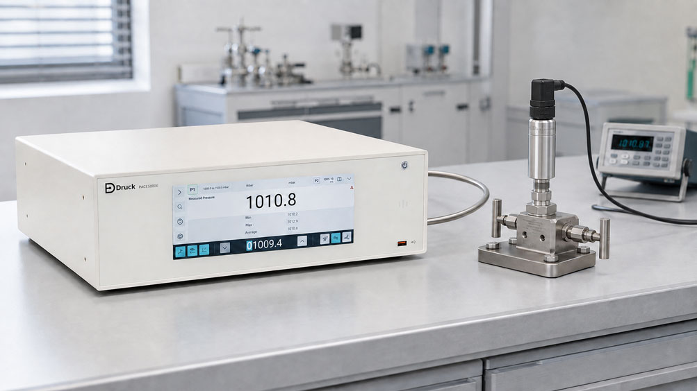
The PACE5000E automatically generates, controls and measures pneumatic pressure. In combination with a suitable control module, defined test points can be approached reproducibly in ascending and descending order and documented using automated routines.
PACE CM3 – Reference Module for High-Accuracy Requirements
The PACE CM3 is a high-accuracy control module for the PACE series. It is suitable for calibration and test tasks in which control stability, long-term stability and low reference uncertainty are crucial. The pressure range and permissible pressure medium must be suitable for the application.
PACE6000E – Two Pressure Channels for Advanced Test Benches
The PACE6000E provides two control channels. It is suitable for automated test benches where two pressure ranges, two devices under test or more complex sequences need to be covered flexibly.
DPI610E – Complete On-Site Calibration with Manual Pressure Generation
The DPI610E or DPI610E-IS combines pressure generation, reference measurement, electrical measurement functions and documentation in one portable instrument. This allows ascending and descending series to be performed directly at the plant. The test points must be controlled manually and approached from an unambiguous direction.
PV624 with DPI620G – Portable Automatic Stabilisation
The PV624 hybrid pressure controller base combines manual coarse pressure generation with automatic fine control. Together with the DPI620G and suitable PM620 pressure modules, it supports stable, documentable pressure points in mobile calibration applications.
Further reference instruments, pressure controllers, calibrators and pumps can be found in the Calibration Equipment category at ICS Schneider.
Conclusion
An ascending and descending calibration reveals direction-dependent deviations that cannot be detected by an ascending series alone. Hysteresis is the difference between the results at the same pressure point under different loading directions. Linearity, by contrast, describes the deviation of a characteristic curve from a defined straight line, while repeatability evaluates the scatter under comparable conditions.
For a reliable separation, the same test points must be approached without unintended changes of direction. Preloading, stabilisation, temperature, zero point, head correction, leakage and the electrical measurement chain must remain controlled throughout the entire cycle.
The number of test points and measurement series depends on the calibration procedure used and the target uncertainty. Clear documentation of the ascending value, descending value, mean value, hysteresis and zero return enables both a traceable conformity assessment and targeted root-cause analysis.
FAQ: Hysteresis in Pressure Calibration
Why must a pressure sensor be calibrated in ascending and descending directions?
This is the only way to identify whether the sensor produces different values at the same pressure point depending on the previous loading direction. An ascending series alone cannot determine this hysteresis.
How is hysteresis calculated?
At the same reference pressure, the ascending value is subtracted from the descending value. The absolute value of this difference is often stated in pressure units, output units or as a percentage of the measuring span.
Is hysteresis the same as linearity deviation?
No. Hysteresis is direction-dependent. Linearity deviation describes the deviation of a characteristic curve from a defined reference line. Both characteristics must be assessed separately using a clearly stated method.
May the sensor be re-zeroed between the ascending and descending series?
Normally not, because doing so would alter the loading history and part of the deviation being investigated. However, the specified calibration procedure is always decisive.
What happens if a test point is overshot?
Regulating back causes the point to be approached from the wrong direction. For high-accuracy calibrations, the test point should be reached again from the intended direction.
How long should the system be allowed to settle at each pressure point?
There is no universal waiting time suitable for every setup. The waiting time must be long enough for the reference pressure and DUT signal to meet the specified stability criterion.
Why is the head correction important?
If the reference levels are at different heights, the reference and DUT are not exposed to exactly the same pressure. The hydrostatic difference can be relevant, especially with liquids and low pressure ranges.
What is the difference between hysteresis and repeatability?
Hysteresis compares different loading directions. Repeatability describes the scatter observed when measurements are repeated under conditions that are as identical as possible and in the same direction.
Should the ascending value, descending value or mean value be used for the characteristic curve?
This depends on the intended use and evaluation method. If the mean value is used, the remaining direction dependence must still be documented or included in the measurement uncertainty.
Can a pressure controller determine hysteresis automatically?
A pressure controller can automatically approach defined points in ascending and descending order. To calculate hysteresis, however, the DUT values must be recorded correctly, assigned to the corresponding reference values and evaluated using a specified method.
How does temperature affect the calibration?
Temperature drift of the DUT, reference and pressure medium can create a time-dependent difference between the series that looks like hysteresis. Adequate acclimatisation and stable environmental conditions are therefore important.
How is zero return checked?
The zero value after the complete descending series is compared with the zero value recorded before loading. The setup must actually be depressurised or at the defined lower reference point.