


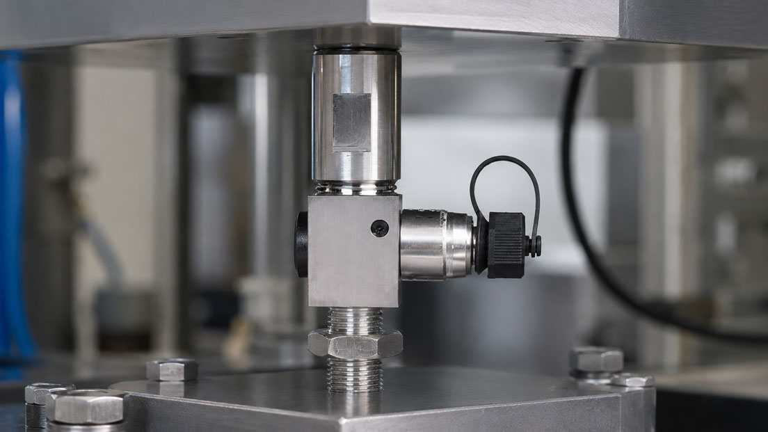
Force transducers used in test benches, presses, assembly fixtures, weighing systems and machines are frequently loaded close to their rated range. Under normal operating conditions, the measurement works reliably. However, a blocked mechanism, a hard end stop, a dropped tool or an unexpected impact load can overload the sensor within a very short time.
An overload does not necessarily cause visible breakage of the measuring body. Even slight permanent deformation can shift the zero point, alter the characteristic curve or impair repeatability. The force transducer may continue to provide a signal afterwards, but it may no longer measure reliably.
Mechanical stops can limit movement before the measuring body exceeds its permissible deformation range. They are particularly useful when overloads cannot be completely ruled out or when an electronic shutdown would respond too late to rapid load peaks.
Table of Contents
- Why force transducers are damaged by overload
- Distinguishing rated force, maximum operating force and breaking force
- Typical causes of mechanical overload
- How a mechanical overload stop works
- Designing the stop and clearance correctly
- Overload protection for compression and tensile forces
- Considering dynamic forces and impact loads
- Avoiding transverse forces, bending moments and torsion
- Distinguishing an intentional overload path from an unwanted force shunt
- Considering the stiffness of the surrounding structure
- Combining mechanical and electronic protection
- Providing protection during transport and installation
- Commissioning and functional testing
- What must be checked after an overload
- Maintenance and visual inspection
- Typical design and installation errors
- Practical example: Compression-force measurement in an assembly fixture
- Information required for the design
- Which products are suitable?
- Conclusion
- Frequently asked questions
Why force transducers are damaged by overload
Many electrical force transducers operate using strain gauges or thin-film sensor technology. The force deforms a metallic measuring body within a precisely defined elastic range. This very small deformation is converted into an electrical signal.
As long as the load remains within the permissible limits, the measuring body largely returns to its original shape after the load is removed. If the limit is exceeded, plastic deformation may occur.
Possible consequences include:
- permanent zero-point shift,
- changed sensitivity or span,
- poorer linearity,
- altered hysteresis,
- poorer repeatability,
- cracks or material fatigue,
- damage to strain gauges, conductor tracks or bonded joints,
- complete mechanical failure.
A force transducer can appear undamaged externally while no longer complying with its original specification. The presence of an output signal is therefore not sufficient evidence that the sensor is still measuring the force correctly.
Distinguishing rated force, maximum operating force and breaking force
Depending on the manufacturer, force-transducer data sheets contain different load ratings. The terminology and reference values used must be checked for the specific sensor.
| Characteristic | Meaning | Practical relevance |
|---|---|---|
| Rated force Fnom | Upper value of the intended measuring range | The specified metrological characteristics apply within this range |
| Permissible operating force | Maximum permissible load at which no permanent damage should occur | Not a recommended continuous load for normal measurement operation |
| Limit force or safe overload | Manufacturer-specific load limit above the rated force | Must be regarded only as a protective reserve and not as an additional measuring range |
| Breaking force | Load at which mechanical failure is to be expected | Must not be treated as a usable operating reserve |
| Rated displacement | Deformation travel of the measuring body at rated force | An important basis for designing a mechanical stop |
A high breaking force does not mean that the sensor will continue to measure accurately after every load below this value. A permanent metrological change may already occur between the end of the specified measuring range and mechanical failure.
The overload ratings for tensile and compression directions may also differ. With bidirectional force transducers, both directions must therefore be assessed separately.
Typical causes of mechanical overload
Overloads are not caused solely by selecting the wrong measuring range. The cause often lies in the actual machine movement or an unexpected operating condition.
Typical examples include:
- a tool moves against a fixed end stop,
- a test specimen becomes blocked during a pressing or joining operation,
- a cylinder generates a higher force than expected at full operating pressure,
- a component is clamped suddenly,
- a load falls onto a weighing platform,
- a tool or adapter is dropped onto the sensor,
- a motor or spindle continues moving after the shutdown signal,
- pressure accumulators or flywheels supply additional energy,
- an operator uses an incorrect test sequence,
- transport or installation forces act on the sensor.
Transverse forces can also overload the measuring body mechanically even though the indicated axial force remains below the rated force. Protection must therefore take into account not only the expected numerical value but also the complete force and movement sequence.
How a mechanical overload stop works
A mechanical overload stop limits the possible deformation travel of the load cell or the connected structure.
Within the normal measuring range, there is a defined clearance between the moving component and the stop. The entire force is transmitted through the force transducer.
Only when the movement reaches the permissible limiting travel does the structure contact the stop. Any additional load is then transmitted completely or partially through the stronger overload path.
A correctly designed stop therefore fulfils two requirements:
- It does not influence the measurement up to the intended maximum force.
- It limits sensor deformation before harmful overload occurs.
Possible designs include:
- adjustable stop screws,
- spacer sleeves and stop surfaces,
- stops integrated into the force transducer,
- separate overload plates,
- preloaded spring assemblies with an end stop,
- mechanical bypass structures,
- tension and lift-off restraints with limited travel.
Designing the stop and clearance correctly
The required stop clearance must not be defined using a general rule. It depends, among other factors, on:
- rated displacement of the force transducer,
- permissible overload travel,
- stiffness of the base plate and load application structure,
- deformation of bolts and adapters,
- thermal expansion,
- manufacturing tolerances,
- wear and settling behaviour,
- the required engagement threshold.
As a design principle, the stop is often adjusted to a travel slightly greater than the normal rated displacement. However, the precise value must be derived from the manufacturer’s data and the deformation of the complete structure.
The stop must be sufficiently rigid. If the stop structure itself yields significantly, the force transducer can continue to deform and become overloaded despite contact with the stop.
Controlled loading of the complete measuring system is advisable when making the adjustment:
- Install the force transducer correctly and connect it electrically.
- Check the normal zero point without contact with the stop.
- Apply the intended maximum operating force in a controlled manner.
- Check or adjust the remaining clearance to the stop.
- Increase the load carefully up to the intended engagement point.
- Remove the load and check the zero point and repeatability.
- Document the engagement point and adjustment dimension.
Adjustment based solely on a theoretical drawing may be inadequate if the base frame, platform or adapter deforms more than expected.
Overload protection for compression and tensile forces
Compression loading
With compression force transducers, an overload stop can often be implemented using a parallel stop surface or an adjustable screw. Once the defined travel is reached, the load application structure is supported by the rigid surrounding structure.
It must be ensured that:
- the force continues to be applied as centrally as possible,
- the stop surfaces are parallel,
- no lateral displacement occurs,
- the stop does not contact the load cell during normal operation,
- the stop structure can safely absorb the maximum fault load.
Tensile loading
Overload protection in the tensile direction is more demanding from a design perspective. Possible solutions include tie rods, retaining brackets or interlocking components with defined free movement.
The retaining mechanism must take over the load before the permissible tensile travel of the force transducer is exceeded. At the same time, it must not transmit any part of the force during normal loading.
Alternating tensile and compression loading
Bidirectional applications frequently require two separate movement limits:
- a stop for the compression direction,
- a retaining or limiting device for the tensile direction.
Clearance, hysteresis and possible changes in load direction must be considered. Protection that works in the compression direction does not automatically protect the sensor against tensile overload.
Considering dynamic forces and impact loads
A statically calculated force is insufficient for the design if masses move rapidly or are decelerated abruptly.
The kinetic energy is calculated in simplified form as:
E = ½ × m × v2
The shorter the distance over which this energy is absorbed, the higher the resulting peak force can be. A hard metal stop may limit the sensor travel, but at the same time introduce a very high impact force into the surrounding structure.
The following additional measures may be appropriate in dynamic applications:
- spring assemblies,
- elastomer dampers,
- hydraulic shock absorbers,
- reduced travel speed before the end position,
- mechanical or slip clutches,
- pressure limitation for hydraulic or pneumatic drives.
A damping element must not alter the force measurement uncontrollably within the intended measuring range. If it is permanently integrated into the force path, its spring stiffness, hysteresis and temperature dependence must be assessed.
Fatigue strength is also important with recurring load peaks. A load below the single-event overload limit can still cause premature failure if it occurs over a very large number of load cycles.
Avoiding transverse forces, bending moments and torsion
An axial stop does not automatically protect against incorrect force application. Transverse forces, bending moments and torsion can damage the measuring body before the axial stop is reached.
Typical causes include:
- misaligned threads,
- inclined cylinders or spindles,
- uneven supporting surfaces,
- tools moving sideways,
- distorted machine frames,
- rigid pipes or cables,
- twisting while tightening fasteners,
- oversized or excessively heavy adapters.
Suitable countermeasures include:
- flat and sufficiently hard mounting surfaces,
- central force application,
- rod ends or self-aligning load buttons,
- torsion-resistant installation,
- separate guides for transverse movement,
- short and rigid force paths,
- stress-free routing of cables and pipes.
Rod ends can compensate for minor angular misalignment. However, they cannot compensate for significant lateral displacement and do not replace correctly aligned mechanics.
Distinguishing an intentional overload path from an unwanted force shunt
A mechanical stop deliberately creates a second force path during an overload. Within the normal measuring range, however, this path must not be active.
If the stop already contacts the structure during normal measurement, part of the force bypasses the sensor. This unwanted force shunt frequently causes:
- an indication that is too low,
- a non-linear characteristic curve,
- poor repeatability,
- different values with increasing and decreasing loads,
- temperature-dependent measurement errors.
Contamination can also bridge the free clearance. Swarf, product residues, corrosion or hardened lubricant can cause the stop to engage prematurely.
The stop area should therefore be:
- protected against coarse contamination,
- accessible for inspection and cleaning,
- made from corrosion-resistant materials,
- clearly adjustable and securely locked
.
Considering the stiffness of the surrounding structure
The stop reacts not only to deformation of the force transducer. The base plate, load plate, adapters, bolts and machine frame also move under load.
If the surrounding structure is insufficiently rigid, the following can occur:
- The stop engages too early and restricts the normal measuring range.
- The base plate bends without adequately protecting the sensor.
- The stop contacts on one side only and generates a bending moment.
- The engagement threshold changes depending on the load position.
Platform deflection must be considered particularly with platform scales and large load application structures. A centrally adjusted stop may behave differently under an off-centre load.
The overload protection must therefore be tested on the actual structure and not only on the removed force transducer.
Combining mechanical and electronic protection
An electronic limit can stop the drive, close a valve or trigger a warning. It is an important supplement to mechanical protection.
An electronic shutdown typically consists of:
Force transducer → measuring amplifier → limit evaluation → controller → actuator shutdown
All delays must be considered during the assessment:
- mechanical response time of the sensor,
- filtering in the measuring amplifier,
- sampling rate of the analogue input,
- PLC cycle time,
- program execution time,
- shutdown time of the valve or drive,
- mechanical overrun.
With slow processes, an electronic shutdown may respond in time. In the event of a hard impact or a rapidly blocking press, the damaging peak force may already occur before the machine comes to a standstill.
A robust protection strategy can therefore include several levels:
| Protection level | Function |
|---|---|
| Adequately selected measuring range | Reserve for normal process fluctuations |
| Pre-alarm | Early warning of an unusually high force |
| Electronic shutdown | Stops the process before a sustained overload occurs |
| Mechanical stop | Limits the deformation travel during rapid or uncontrolled events |
| Mechanical failure restraint | Prevents uncontrolled release or falling in the event of component failure |
A conventional force transducer and a simple PLC limit are not automatically components of a safety-related control system. For personal protection or legally required safety functions, the complete safety chain must be designed and assessed accordingly.
Providing protection during transport and installation
Force transducers can be damaged even before commissioning. Impacts during transport and installation often occur in an uncontrolled manner and without active measured-value monitoring.
Useful protective measures include:
- transport restraints,
- rigid installation dummies instead of the load cell,
- installation of the sensor only at the final installation location,
- mechanical unloading during welding and alignment work,
- electrical connection and measured-value monitoring during installation,
- protection against falling tools,
- not using the sensor as an installation support.
If a weighing system or machine is transported with force transducers installed, vibrations and hard impacts can generate considerably higher peaks than those occurring during subsequent normal operation.
Commissioning and functional testing
The complete mechanical and electrical measuring chain should be tested before normal operation.
- Identify the sensor: Check the rated force, permissible overload, measuring direction and rated displacement.
- Check the installation: Inspect the supporting surfaces, threads, rod ends and alignment.
- Observe the zero signal: Monitor the sensor electrically while tightening the fasteners.
- Check the clearance: Ensure that the overload stop is not contacted in the unloaded condition or within the normal measuring range.
- Increase the load slowly: Apply several defined test points up to the maximum operating force.
- Check the stop: Verify the engagement point using a suitable procedure.
- Test the limits: Check the pre-alarm and controller shutdown.
- Remove the load: Verify the return to zero and repeatability.
- Document the results: Record the clearance, stop position, limits and test results.
An intentional overload test may be performed only if the sensor, stop and test setup are explicitly designed for this purpose. The permissible manufacturer limits must not be exceeded for experimental purposes.
What must be checked after an overload
After a suspected overload, the force transducer should not simply be re-zeroed and returned to service. Electronic zeroing can conceal a permanent mechanical change.
The following should be checked:
- zero signal before and after the event,
- visible deformation or cracks,
- damage to threads and supporting surfaces,
- condition of the cable and connector,
- repeatability under several identical loads,
- sensitivity at at least one known reference point,
- behaviour in the tensile and compression directions,
- function of the mechanical stop.
Indications of possible damage include:
- a new zero-point offset,
- reduced span,
- an erratic signal,
- different values under repeated loading,
- slow return to zero,
- unusual hysteresis.
If relevant deviations are found, the sensor should be taken out of service and inspected by the manufacturer or a suitable calibration laboratory.
Following a significant overload, calibration at several increasing and decreasing force points is advisable. Only this can determine whether the zero point, sensitivity, linearity and hysteresis remain within the required limits.
Maintenance and visual inspection
Mechanical overload protection remains reliable only if the clearance, stop surfaces and fasteners are maintained.
The following should be checked during recurring inspections:
- free clearance in the unloaded condition,
- secure seating of the adjustment screws,
- protection against unintended adjustment,
- wear or plastic deformation of the stop surfaces,
- dirt, swarf or corrosion in the clearance,
- cracks and loose fasteners,
- zero point and reference value of the sensor,
- function of the alarm and shutdown.
The inspection interval should be based on the load, dynamics, contamination and importance of the measuring point. An additional inspection is required after a documented overload or impact event.
Typical design and installation errors
The stop already contacts within the normal measuring range
Part of the force bypasses the sensor. The measured value, linearity and repeatability are distorted.
A standard stop clearance is adopted without assessment
The rated displacement, structural stiffness and tolerances differ. The stop engages either too early or too late.
Only axial overload is considered
Transverse forces or bending moments damage the sensor without the axial stop responding.
The stop plate is insufficiently rigid
The plate bends under load and does not adequately limit sensor travel.
The stop is positioned on one side only
An additional bending moment is generated when the stop engages.
Contamination in the stop clearance is not considered
Swarf or product residues create a premature force shunt.
Electronic shutdown is used as the only protection
With rapid impact loads, the maximum force occurs before the machine comes to a standstill.
An oversized sensor is selected as a simple solution
Overload protection improves, but resolution and relative measuring accuracy within the actual operating range may become poorer.
Only the tare is reset after an overload
A permanent change in the characteristic curve remains undetected.
The machine is transported with unprotected load cells
Impacts and vibrations damage the sensors before commissioning.
Practical example: Compression-force measurement in an assembly fixture
In an automated assembly fixture, a plastic component is pressed into place using an electric spindle. The normal process force is a maximum of 8 kN. If components are inserted incorrectly, however, the spindle can move against an almost rigid obstruction.
The installation uses a compression force transducer with a rated force of 10 kN. Initial tests show short-term force peaks of more than 12 kN before the PLC shuts down the drive.
The previous protection strategy consists only of a software limit at 9 kN. However, the following delays and effects occur between reaching this value and coming to a standstill:
- filter time of the measuring amplifier,
- PLC cycle time,
- response time of the drive,
- kinetic energy of the spindle and tool.
The design is therefore modified:
- The force transducer is installed on a rigid and flat-machined base plate.
- An adjustable, symmetrical compression stop is arranged parallel to the sensor.
- The stop remains clear until above the maximum normal process force.
- The controller reduces the travel speed from 7 kN.
- A pre-alarm is triggered at 8.5 kN.
- Electrical shutdown takes place at 9 kN.
- The mechanical stop limits any further travel if the process is not stopped in time.
After adjustment, the measuring chain is tested using defined reference forces. Up to 8 kN, the sensor shows no discernible influence from the stop. During a simulated blockage, the stop structure takes over the additional load before the permissible sensor travel is exceeded.
The example shows that a mechanical stop is not used instead of process monitoring. It forms the final protection level in case the control or shutdown system does not sufficiently limit the dynamic force peak.
Information required for the design
At least the following information is required when selecting a force transducer and planning overload protection:
- measuring direction: tension, compression or tension and compression,
- minimum and maximum normal force,
- short-term load peaks,
- possible fault and blocking forces,
- static or dynamic loading,
- speed and moving mass,
- expected number of load cycles,
- rated force and permissible sensor overload,
- rated displacement or deformation travel,
- installation space and existing mechanics,
- stiffness of the base and load plates,
- possible transverse forces and bending moments,
- required mechanical engagement point,
- existing electronic shutdown,
- ambient temperature, contamination and degree of protection,
- required accuracy and calibration,
- personal- or machine-protection requirements.
A meaningful enquiry could read as follows:
Compression force transducer for an electric assembly fixture, normal measuring range 0 to 8 kN, possible blocking force up to 20 kN, dynamic loading, maximum installation height 50 mm, 0–10 V output, mechanical overload stop required, limit shutdown via PLC and calibration of the complete measuring chain.
Which products are suitable?
Force sensors and force-measuring instruments
The force sensors / force-measuring instruments category includes various solutions for force, load, displacement, torque and machine measurements.
Depending on the application, the following are available for force-measuring tasks:
- compression force transducers,
- tension/compression force transducers,
- S-type load cells,
- ring force transducers,
- miniature force transducers,
- load pins and tension links,
- strain transducers,
- sensors with mV/V, 4–20 mA, 0–10 V or digital signals.
When selecting the equipment, the measuring range, overload capability, force application, rated displacement, output signal and mechanical protection structure should be considered together.
WIKA F1226 miniature compression force transducer
The WIKA model F1226 is a compact compression force transducer for applications with limited installation space.
Miniature force transducers are particularly sensitive to installation errors. The output signal should be monitored during installation so that preloads or unintended overloads are detected at an early stage.
The supporting surface, central force application and any required external stop must be coordinated for the specific application.
WIKA F2304 tension/compression force transducer
The WIKA model F2304 is intended for axial tension and compression force measurements in machines and installations.
Typical applications include:
- screw presses,
- lifting cylinders,
- punching and pressing machines,
- welding guns,
- machine monitoring and overload control.
With alternating tensile and compression loading, the connections must be free from play and correctly aligned. Mechanical overload protection must be assessed separately for both force directions.
Special force transducers and strain transducers
The special force transducers / strain transducers category includes solutions for applications in which standard designs do not fit the available installation space or force path.
Special solutions may be useful for:
- very limited installation space,
- high or unusual forces,
- existing machines that cannot be fundamentally modified,
- special force paths,
- redundant force monitoring,
- integrated mechanical overload protection.
A strain transducer is mounted on an existing machine component and measures its deformation. After calibration, this deformation can be assigned to a force. This allows an existing structure to be monitored in some cases without direct intervention in the main force path.
Conclusion: The stop must protect the sensor without influencing the measurement
A force transducer can be permanently altered by a short load peak, blocked mechanism or installation error. A sensor that appears externally undamaged may subsequently no longer measure within its original specification.
A mechanical stop limits the deformation travel and takes over the additional load before the measuring body is damaged. This requires correctly adjusted clearance: within the normal measuring range, the stop must not create a force shunt.
The required clearance must be derived from the sensor’s rated displacement, permissible overload and deformation of the complete structure. The base plate, load application structure, bolts and adapters must be sufficiently rigid.
Transverse forces, bending moments and torsion require separate design measures. An axial stop cannot compensate for incorrect force application.
In dynamic applications, mechanical protection should be combined with speed reduction, electronic limits and, where necessary, damping. The mechanical limitation then forms the final protection level against rapid or uncontrolled loads.
After an overload, simply performing a new zero adjustment is not sufficient. The zero point, sensitivity, repeatability and characteristic curve must be checked using known reference forces.
Frequently asked questions about overload protection for force transducers
When is a mechanical overload stop useful?
It is particularly useful when unknown loads, blocking conditions, impact loads or operating errors cannot be ruled out reliably and an electronic shutdown may respond too late.
How large must the clearance to the stop be?
The clearance depends on the sensor and structure. It must allow the normal rated displacement, including tolerances and deformation of the surrounding structure, while still limiting the sensor before harmful overload occurs.
May the stop already be in contact at rated force?
Normally not. It would take over part of the force and create a force shunt. The precise engagement point must be defined using the manufacturer’s data and the application requirements.
Is a force transducer with a larger measuring range sufficient as overload protection?
A higher rated force provides additional reserve but may reduce the usable resolution and relative accuracy within the normal operating range. The sensor range and overload protection should therefore be designed together.
Can a PLC shutdown replace the mechanical stop?
An electronic shutdown may be sufficient for slow loading. During rapid impacts, however, filter, PLC, drive and overrun times take effect. A mechanical stop may therefore still be necessary.
Does a compression stop also protect against transverse forces?
No. Transverse forces, bending moments and torsion can damage the force transducer independently of axial travel. Correct guidance and central force application are required for this purpose.
What should be done after an overload?
The sensor should be unloaded and checked for zero-point shift, visible damage, repeatability and sensitivity. If relevant deviations are found, a multipoint force calibration or manufacturer inspection is required.
Why can dirt at the stop distort the measurement?
Swarf or deposits can bridge the free clearance. The stop then takes over part of the force within the normal measuring range.
Which information does ICS Schneider require for selection?
The required information includes the normal and maximum forces, possible load peaks, tensile or compression direction, dynamics, installation space, force application, possible transverse forces, rated displacement, required output signal, electronic shutdown and requirements for mechanical protection and calibration.