


Compressed-air leaks often remain undetected in industrial installations for a long time. Small leaks at couplings, hoses, valves or threaded connections are difficult to hear in a noisy production environment. Nevertheless, compressed air frequently escapes around the clock and must continually be regenerated by the compressor.
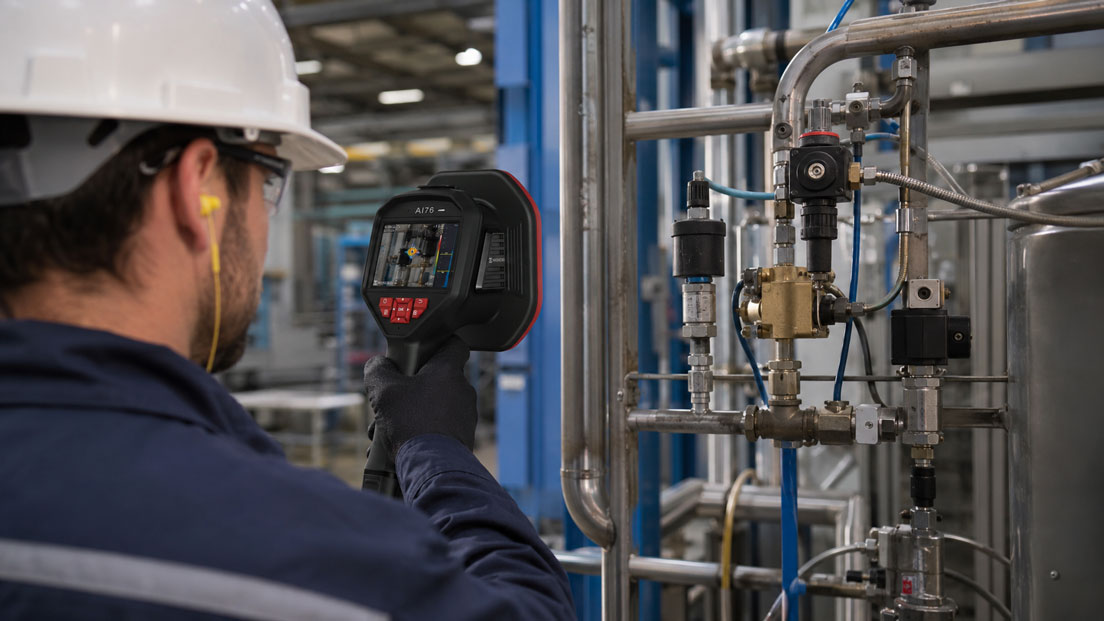
An acoustic camera visualises the ultrasonic signals generated by a leak directly within the camera image. This allows maintenance personnel to inspect larger areas of an installation from a distance, identify multiple sound sources more quickly and immediately document the leaks found.
Modern instruments can additionally display an estimated leak rate and the resulting annual costs. This turns simple troubleshooting into a structured maintenance process: find, assess, prioritise and repair leaks, and then inspect them again.
Table of Contents
- Why compressed-air leaks become so expensive
- How an acoustic camera makes leaks visible
- Why leaks generate ultrasound
- Acoustic camera or conventional ultrasonic leak detector?
- Leak detection during ongoing production
- Assessing interfering noise and reflections correctly
- Estimating the leak rate and leakage costs
- Prioritising detected leaks appropriately
- Inspecting the compressed-air network systematically
- Typical leak locations in compressed-air systems
- Documenting and marking leaks
- Repair and follow-up inspection
- Limitations of acoustic leak detection
- Typical application errors
- Practical example: Leak audit in a production hall
- Selecting the correct acoustic camera
- Which products are suitable?
- Conclusion
- Frequently asked questions
Why compressed-air leaks become so expensive
Compressed air is generated using electrical energy, then treated, dried and transported through a pipe network to the consumer. If some of the air escapes through leaking points, the compressor must compensate for these losses.
The consequences may include:
- longer compressor operating times,
- higher electricity consumption,
- more frequent load and unload cycles,
- additional wear on compressors and air-treatment equipment,
- pressure drops at remote consumers,
- impairment of pneumatic processes,
- unnecessary expansion of compressor capacity.
A single small leak is often barely noticeable during production. However, many small leaks can together result in a considerable continuous volumetric flow loss.
Leak elimination should therefore not be regarded solely as a repair measure. It forms part of continuous energy and plant optimisation.
How an acoustic camera makes leaks visible
An acoustic camera combines an optical camera image with an array of multiple microphones. The microphones detect sound from different directions and with slight differences in arrival time.
A beamforming algorithm evaluates these differences and calculates the direction from which the ultrasonic signal originates. The detected sound source is then overlaid as a coloured area on the actual camera image.
The user can therefore see simultaneously:
- the area of the installation being inspected,
- the direction of the strongest sound source,
- where applicable, several leaks within the field of view,
- the sound level or leak severity,
- an estimated leak rate,
- an estimated cost impact.
The camera does not have to be held directly against every individual threaded connection. An entire machine area can initially be inspected from a greater distance. The suspicious location is then narrowed down more precisely from a more suitable position.
Why leaks generate ultrasound
When compressed air or another pressurised gas flows through a small opening, turbulent flow is created. This produces a broadband sound signal containing frequencies above the range of human hearing.
These ultrasonic components are particularly useful for leak detection because many typical ambient noises from motors, fans or conversations occur predominantly within the audible frequency range.
The strength of the generated signal depends, among other factors, on:
- the pressure difference across the leak,
- the shape and size of the opening,
- the type of gas,
- the distance from the measuring instrument,
- the orientation of the leak,
- shielding and reflections,
- ambient noise within the selected frequency range.
A leak may therefore be clearly detectable from one measuring direction and appear weaker from another.
Acoustic camera or conventional ultrasonic leak detector?
| Criterion | Acoustic camera | Conventional ultrasonic leak detector |
|---|---|---|
| Localisation | The sound source is visualised within the camera image | The signal is traced using headphones, an indication or a level reading |
| Inspected area | A larger area of the installation is visible simultaneously | Usually point-by-point or directional searching |
| Multiple leaks | Depending on the instrument, several leaks can be detected simultaneously | Normally located one after another |
| Distance | Initial detection is frequently possible from a greater distance | Closer approach is often required for precise localisation |
| Documentation | Images, measured values, leak rates and costs can be stored | Depending on the instrument, photos, notes or manual documentation |
| Concealed leaks | Direct line of sight and a suitable measuring direction are advantageous | Probes and directional tubes can be more flexible in confined areas |
| Investment | Higher instrument cost, but rapid inspection of large installations | Lower cost and often sufficient for individual inspections |
An acoustic camera is particularly advantageous when numerous pipes, machines or difficult-to-access connections must be inspected regularly. A conventional ultrasonic instrument can remain useful when individual concealed locations must be examined very precisely.
The two methods can complement one another: the camera rapidly identifies the suspicious area, while the point-based leak detector can subsequently narrow down a difficult-to-access location.
Leak detection during ongoing production
A major advantage of acoustic imaging is that compressed-air systems can frequently be inspected during normal operation. The line remains pressurised and actual leaks continue to generate their characteristic ultrasonic signal.
This means that leaks occurring only under specific operating conditions can also be detected, for example:
- while a cylinder is pressurised,
- at a particular valve position,
- under full machine load,
- at high network pressure,
- on moving hose lines,
- during an automatic production cycle.
Testing during operation avoids additional production downtime. At the same time, the user must observe the operational hazards. Moving machine parts, electrical installations, hot surfaces and traffic routes must not be entered or reached across merely to obtain a more favourable camera position.
Assessing interfering noise and reflections correctly
An acoustic camera may also indicate a strong ultrasonic signal that does not originate from an unwanted leak.
Possible sources of interference include:
- open blow-off nozzles,
- vacuum generators and Venturi systems,
- pneumatic exhausts,
- rapidly switching valves,
- cleaning nozzles,
- steam or gas flows,
- electrical partial discharges,
- machine components generating high-frequency friction noise.
Metal walls, housings and large vessels can reflect ultrasound. The area displayed within the image may therefore be displaced from the actual leak location.
For plausibility checking, the location should be observed from at least two different directions. If the displayed source moves across a reflective surface as the camera position changes, the actual source must be narrowed down further.
Helpful measures include:
- adjusting the frequency range,
- changing the distance and viewing angle,
- adapting the sensitivity to the environment,
- temporarily switching off a possible interference source,
- shielding reflective surfaces,
- confirming the leak from several positions.
Estimating the leak rate and leakage costs
Many acoustic cameras can calculate an estimated leak rate from the measured sound signal. The value may be displayed in l/min or m³/h, for example.
For a meaningful estimate, the instrument settings must match the installation. Particularly relevant factors include:
- operating pressure,
- gas type,
- measuring distance,
- operating hours per year,
- electricity or compressed-air costs,
- where applicable, specific compressor data.
The cost estimate is particularly helpful when comparing a large number of detected leaks. However, it is not a direct flow measurement performed at the leak itself.
Deviations can result from:
- an incorrectly entered pressure,
- an inaccurate measuring distance,
- sound reflections,
- several closely spaced sources,
- fluctuating plant operation,
- different leak geometries.
Leakage costs should therefore be regarded as a practical prioritisation value rather than an exact billing value.
Prioritising detected leaks appropriately
It is rarely economical to repair all detected leaks immediately and without planning. Prioritisation according to technical and economic significance is more appropriate.
| Priority | Typical criteria | Recommended response |
|---|---|---|
| Very high | Large leak rate, safety-critical or process-critical location | Secure and repair as quickly as possible |
| High | High annual costs, easily accessible repair | Repair during the next maintenance window |
| Medium | Smaller leak at a machine or distribution point | Combine with planned maintenance work |
| Low | Very small leak requiring considerable repair effort | Monitor and address during the next plant overhaul |
Economic priority does not depend solely on the leak rate. A small leak at an easily accessible coupling can be eliminated within a few minutes. A leak of a similar size in a difficult-to-access pipe may require planned downtime.
Inspecting the compressed-air network systematically
A structured inspection is more reliable than randomly searching for audible leaks.
- Define the inspection area: Clearly specify the building, hall, machine or compressed-air section.
- Document the operating condition: Record the network pressure, active compressors and operating consumers.
- Configure the instrument: Set the pressure, gas type, cost parameters and measuring distance correctly.
- Perform an initial survey: Inspect main lines and machines from a greater distance.
- Narrow down suspicious areas: Reduce the distance and change the viewing angle.
- Confirm the leak: Check the indication from several positions.
- Store the data record: Record the image, leak rate, cost, installation name and position.
- Mark the leak: Clearly identify the location requiring repair.
- Assign a priority: Assess the technical significance, cost and repair effort.
- Arrange the repair: Define the responsible person and completion date.
- Perform a follow-up inspection: Recheck the repaired location under comparable conditions.
The inspection should, wherever possible, always follow the same sequence. This reduces the risk of overlooking sections and improves the comparability of results from different inspections.
Typical leak locations in compressed-air systems
| System area | Typical leak locations | Special consideration |
|---|---|---|
| Pipe network | Threads, flanges, press fittings, transitions and branches | Leaks may result from vibration and temperature changes |
| Couplings | Quick couplings, push-in connectors and hose connections | Wear or lateral loading are frequent causes |
| Hoses | Porous sections, abrasion points, kinked areas and hose ends | The leak may change depending on movement |
| Valves | Housing seals, connections, coil areas and exhausts | Do not confuse intended exhaust air with a leak |
| Pneumatic cylinders | Piston and rod seals as well as connection fittings | Internal leaks cannot always be clearly located from outside |
| Air-preparation units | Filter housings, pressure regulators, sight glasses and condensate drains | Automatic drains may open temporarily |
| Machine connections | Manifolds, grippers, tools and moving lines | Testing in different machine conditions may be required |
Open blow-off nozzles or continuously operating vacuum generators can consume a large quantity of compressed air even though there is technically no leak. Such consumers should be documented separately as potential efficiency improvements.
Documenting and marking leaks
A leak is only usefully recorded when the maintenance team can clearly locate it again later.
A complete data record should include:
- a unique leak ID,
- building, hall and machine,
- precise component or connection location,
- image with acoustic marking,
- date and time,
- operating pressure,
- estimated leak rate,
- estimated annual costs,
- priority,
- repair recommendation,
- processing status.
The location can additionally be marked with a numbered tag or removable identification label. The marking must not obstruct moving parts and must not be applied to hot or unsuitable surfaces.
The stored data records can be used to create a leak report for maintenance, plant management or energy management.
Repair and follow-up inspection
After a repair, the leak location should be inspected again using the same or a comparable measuring method.
The follow-up inspection determines:
- whether the original leak has been completely eliminated,
- whether a new leak was created during replacement,
- whether several neighbouring leaks were present,
- whether the component remains tight at the actual operating pressure,
- which costs can genuinely be documented as eliminated.
Simply tightening a threaded connection is not automatically a successful repair. Excessive tightening torque can additionally damage seals, threads or plastic connections.
Recurring leaks at the same location frequently indicate a design-related cause, for example:
- vibration,
- hoses that are too short or under tension,
- unsuitable couplings,
- lateral loading,
- incorrect sealing materials,
- excessively high or strongly pulsating pressure.
Limitations of acoustic leak detection
An acoustic camera is a powerful localisation instrument, but it is not a universal method for every leak-tightness test.
Limitations exist particularly with:
- unpressurised systems,
- very low pressure differences,
- completely concealed leaks,
- leaks inside closed housings,
- strong ultrasonic interference sources,
- pronounced reflections,
- internal leaks without external sound emission,
- applications requiring a prescribed leak-testing method.
An acoustic camera does not replace any legally or normatively required pressure, leak-tightness or leakage-rate test. It localises sound sources and supports the assessment of industrial compressed-air and gas losses.
Typical application errors
The incorrect operating pressure is entered
The leak rate and costs are calculated using an incorrect basis.
The first coloured marking is immediately assessed as a leak
Reflections or intended exhausts may also be displayed.
The distance from the leak is entered incorrectly
The model-based leak-rate estimate may deviate significantly as a result.
Only one measuring direction is used
The actual source may appear concealed or displaced because of a reflective surface.
The machine condition and network pressure are not documented
Subsequent measurements cannot be compared.
Open blow-off nozzles are recorded as leaks
They are intended consumers whose efficiency must be assessed separately.
Leaks are detected but not clearly marked
The maintenance team cannot locate them again later.
No repeat measurement is performed after the repair
An incomplete repair or a second neighbouring leak remains undetected.
Practical example: Leak audit in a production hall
Several assembly lines in a production hall are supplied through a shared compressed-air network. The compressor operates unusually frequently even outside the main production period.
The network is inspected with an acoustic camera during the operating early shift. The operating pressure is 7 bar. The camera is initially directed at the main lines and then at the individual machine areas.
Within two hours, 34 suspicious locations are documented:
- 12 leaking quick couplings,
- 8 leaking hose connections,
- 5 leaks at valve manifolds,
- 4 damaged hose lines,
- 3 leaking air-preparation units,
- 2 permanently open blow-off nozzles.
The largest estimated losses are caused by two damaged hoses and one severely worn coupling. These locations are repaired on the same day.
Smaller leaks are entered into a maintenance order for the next planned machine window. The open blow-off nozzles are not treated as repair cases but are passed to production as optimisation tasks.
After completion of the work, a second inspection is performed. The repaired locations are checked again and documented as completed. At the same time, a new leak is detected that had been masked by an operating exhaust during the initial inspection.
The example shows that an acoustic camera does more than find individual leaks. It enables a repeatable process of recording, cost-based prioritisation, repair and effectiveness verification.
Selecting the correct acoustic camera
At least the following information is required when selecting the instrument:
- compressed air or another pressurised gas,
- typical operating pressure,
- expected size and number of leaks,
- measuring distance,
- size and accessibility of the installation,
- noise conditions within production,
- required leak-rate and cost display,
- detection of several sources simultaneously,
- report generation and data export,
- additional partial-discharge testing,
- battery operating time and weight,
- degree of protection and ambient temperature,
- regular audit use or occasional troubleshooting.
For compressed-air leak detection alone, a model specifically designed for gas leaks is frequently sufficient. If the same instrument is also to be used on high-voltage installations for detecting partial discharge, an appropriately equipped multifunction camera is advisable.
Which products are suitable?
Leak detection and leak measuring instruments
The leak detection / leak measuring instruments category includes acoustic cameras, ultrasonic leak detectors and special instruments for gas, water and pipe testing.
HIKMICRO AI56L
The HIKMICRO AI56L acoustic imaging camera is designed specifically for locating compressed-air and gas leaks in industrial installations.
Its main features include:
- 64 low-noise MEMS microphones,
- real-time acoustic imaging,
- estimation of the leak rate, cost and leak severity,
- adjustable frequency range,
- 4.3-inch LCD touchscreen,
- analysis software and report export.
The AI56L is particularly suitable for regular compressed-air audits and the rapid inspection of larger production areas.
HIKMICRO AI76
The HIKMICRO AI76 features 136 MEMS microphones and enables real-time localisation of gas leaks.
In addition to leak detection, it supports the detection of different types of electrical partial discharge. It is therefore particularly suitable for companies wishing to acoustically inspect both compressed-air installations and medium- or high-voltage electrical installations.
LeakCam 600
The LeakCam 600 visualises compressed-air and gas leaks using a microphone array and can display multiple leaks within the field of view.
Its connection to analysis and reporting solutions supports the structured management of larger leak inventories and recurring compressed-air audits.
ILD 500/510 UltraCam
The ILD 500/510 UltraCam combines an ultrasonic camera with functions for leak assessment and documentation.
Depending on the version, leak rates and costs can be recorded, leak locations can be photographically documented and the results can subsequently be compiled into leak reports using software.
Further information on conventional localisation methods is provided in the article Locating compressed-air leaks.
Conclusion: Acoustic cameras make leak detection faster and more traceable
An acoustic camera visualises ultrasonic signals from compressed-air and gas leaks directly within the actual image of the installation. This allows larger areas to be inspected more quickly and suspicious locations to be narrowed down systematically.
Acoustic imaging offers clear advantages over exclusively point-based searching, particularly in extensive compressed-air networks, installations containing numerous machines and applications requiring regular inspections.
The displayed leak rate and cost assessment enable economical prioritisation. However, their significance depends on correct inputs, the measuring distance, operating pressure and measuring geometry.
Interfering noise, reflections and intended compressed-air consumers must be distinguished from actual leaks. A suspicious location should therefore be confirmed from several directions.
The greatest benefit is achieved through a complete process: systematically inspect the compressed-air network, document leaks, prioritise repairs, define responsibilities and subsequently verify effectiveness with another measurement.
Frequently asked questions about acoustic cameras for compressed-air leaks
Can an acoustic camera detect leaks during ongoing production?
Yes. The installation must be pressurised to generate ultrasound. Many compressed-air leaks can therefore be located during normal operation.
Does leak detection work in a noisy production hall?
Frequently yes, because leaks generate ultrasonic components above many audible machine noises. High-frequency interference sources and reflections must nevertheless be considered.
Does the camera display the exact leak rate?
It provides a model-based estimate using the acoustic signal and configured process parameters. A suitable flow-measuring method is required for an exact flow determination.
How far away can a compressed-air leak be?
The possible distance depends on the leak size, pressure, instrument, environment and unobstructed line of sight. Large leaks can generally be detected from a greater distance than very small leaks.
Can the camera detect several leaks simultaneously?
Depending on the camera and instrument software, multiple sound sources can be displayed within the field of view. However, closely spaced sources or sources with very different sound levels may influence one another.
What is the difference between the AI56L and AI76?
The AI56L is designed for industrial gas and compressed-air leak detection. The AI76 has a larger microphone array and additionally supports the detection and classification of electrical partial discharge.
Must every displayed sound source be repaired?
No. Exhausts, blow-off nozzles and vacuum generators may be intended ultrasonic sources. It must first be determined whether the source is an unwanted leak or a normal consumer.
Why is a follow-up inspection important after the repair?
It confirms that the leak has actually been eliminated and that no new leak was created during replacement. Only then should the case be documented as completed.
Which information does ICS Schneider require for selection?
The required information includes the gas type, operating pressure, size of the installation, typical measuring distance, ambient noise, required leak-rate and cost assessment, documentation requirements and whether partial discharge must also be detected.