


- Measuring ranges 0 … 1 t up to 0 ...4 0 t
- Integrated amplifier, output 4 … 20 mA, 2-wire
- Simple mounting (without opening rope), suitable for retrofits
- Material alloyed steel
- Protection class IP66
 Datasheet Datasheet |
| User Manual |
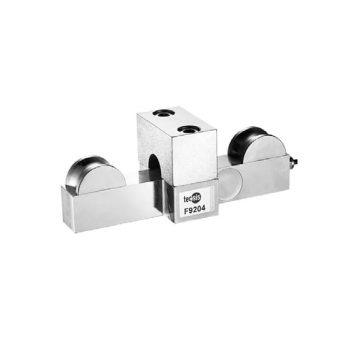
- Measuring ranges 0 ... 6 t up to 0 … 25 t (others possible)
- Relative linearity error 2 % Fnom
- Optimal for retrofitting with simple integration into the crane network through CANopen® and CAN SAE J1939 technologies
- High overload capacity, long service life of the measuring spring, large shock and vibration resistance
- Exceptionally space-saving, ideal for retrofitting onto the spreader
| Datasheet |
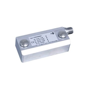
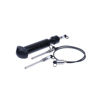
- Measuring ranges strains from 0 ... 200 με up to max. 0 ... 1,000 με
- Good long-term stability, high shock and vibration resistance, good reproducibility
- As retrofitting, easy to install
- For use in extreme outdoor applications (IP67)
- Relative linearity error < 2 % Fnom
| Datasheet |
| User Manual |
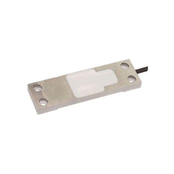
- Strain of 0 … 200 με to max. 0 … 1,000 με
- Can be retrofitted, easy installation with M6-screws
- Total error < 1 % Fnom
- Electrical connection as cable, with plug-in radio module, display or junction box.
| Datasheet |
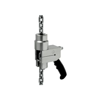
- Measuring ranges 40 ... 3,500 kg
- Simple calibration of friction clutches without weights
- Single sensor concept for entire load range
- Maximum- / minimum value memory
- Relative linearity error 0.5 % Fnom
| Datasheet |
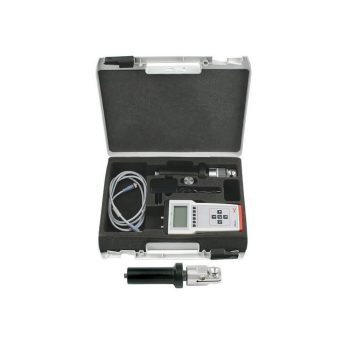
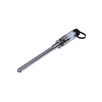
- Measuring ranges 10 kN, 20 kN
- Relative linearity error 0.2 % Fnom
- Low overall weight of approx. 6 kg
- Maximum/Minimum value memory
- Electrode diameter 14 … 20 mm
| Datasheet |
- Measuring ranges 0 ... 6 t up to 0 … 25 t (others possible)
- Relative linearity error < 0.5 % Fnom
- Type tested in accordance with OIML R60 (certificate R60/2000-A-NL-18.05) with D175
- Optimal for retrofitting with simple integration into the crane network through CANopen® and CAN SAE J1939 technologies
- High overload capacity, long service life of the measuring spring, large shock and vibration resistance
| Datasheet |
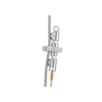
- Measuring ranges 0 ... 1 t to 0 ... 30 t
- Relative linearity error up to ≤ ±1.0 % Fnom
- Wire rope diameter 8 ... 44 mm, suitable for retrofitting
- Material: Stainless steel, IP67
- Optional: Redundant output signal, ATEX version
| Datasheet |
| User Manual |
