


After an extruder has cooled down, a melt pressure sensor can often no longer be removed easily from its mounting hole. Plastic residue may adhere to the process diaphragm, remain inside the guide bore or solidify around the sealing surface. If the sensor is forced out in this condition, the diaphragm, thread, stem or flexible capillary connection may be permanently damaged.
The extremely thin, flush-mounted process diaphragm is particularly sensitive. It must never be prised loose with a screwdriver or cleaned using a wire brush, knife or cleaning drill. Even a small dent or barely visible scratch can affect the zero point, linearity and service life of the sensor.
Safe removal therefore does not begin with a spanner, but with controlled preparation of the machine. The process must be fully depressurised, the polymer around the measuring point must be sufficiently softened and the correct tool must be applied to the designated spanner flats.
Suitable sensors can be found in the Dynisco melt pressure sensors category. Cleaning tools, installation tools and test equipment are grouped together under sensor accessories, tools and pressure calibrators.
Contents
- Why does a melt pressure sensor become stuck after cooling?
- What damage can be caused by forced removal?
- Preparing the machine safely for sensor removal
- Heating and softening the polymer in a controlled manner
- Correctly unscrewing the melt pressure sensor
- What should be done if the sensor cannot be loosened?
- Cleaning the sensor and diaphragm carefully
- Cleaning the mounting hole using the appropriate tool
- Inspecting the removed sensor for damage
- Preparing the thread and reinstalling the sensor
- Correctly storing and transporting the sensor
- Typical errors during removal and cleaning
- Practical example: Stuck sensor at an extruder head
- Which products and tools are suitable?
- Conclusion
- Frequently asked questions
Why does a melt pressure sensor become stuck after cooling?
During operation, the plastic melt is in direct contact with the flush-mounted diaphragm of the sensor. If the mounting hole has been manufactured correctly, the sensor seals against the designated tapered or 45° sealing surface. The thread is used primarily to secure the sensor and generate the necessary contact force.
Polymer can nevertheless make removal difficult if:
- the melt adheres to the diaphragm or sensor tip,
- material enters a damaged or incorrectly manufactured mounting hole,
- the sealing surface is contaminated or not machined concentrically,
- the sensor thread was installed without suitable high-temperature protection,
- the thread has seized because of excessive tightening torque,
- corrosive or abrasive processes have damaged the surfaces,
- the sensor was installed at an angle or cross-threaded.
The polymer contracts as it cools. If it adheres to the diaphragm or front section of the sensor stem, it can hold the sensor firmly in place. If the sensor is then unscrewed while the material is still solid, considerable tensile and torsional forces act on the sensitive sensor tip.
What damage can be caused by forced removal?
Depending on the design, melt pressure sensors have either a rigid stem or a flexible connection between the process connection and the electronics housing. Both designs may only be installed and removed using the designated spanner flats.
Typical damage caused by incorrect removal includes:
- torn or dented process diaphragm,
- bent sensor stem,
- damaged external thread,
- damaged 45° sealing edge,
- twisted or broken capillary line,
- loosened connection between the stem and housing,
- permanent zero-point shift,
- leakage after subsequent reinstallation.
A sensor may still appear intact externally while already having suffered mechanical damage. After forceful removal, it should therefore not be returned to service without inspection.
Preparing the machine safely for sensor removal
Before any work begins, the machine must be secured against unintended start-up. The precise procedure depends on the machine, material and applicable plant safety requirements.
At least the following steps are required:
- Stop the extruder, melt pump or injection-moulding machine in a controlled manner.
- Interrupt the material supply.
- Completely release the process pressure and verify that the system is depressurised.
- Secure the machine against unintended start-up and renewed pressure build-up.
- Allow for hot surfaces and escaping polymer melt.
- Use suitable personal protective equipment.
- Identify the electrical connection of the sensor and disconnect it with the circuit de-energised.
A pressure indication of 0 bar alone is not sufficient if channels may be blocked or plugs of material may trap pressure. The pressure-relief and purging procedure specified by the machine manufacturer must be followed.
Heating and softening the polymer in a controlled manner
The sensor should only be removed once the polymer around the mounting hole is soft or sufficiently molten. The relevant heating zone is therefore brought to a temperature suitable for the material in a controlled manner.
The set cylinder temperature does not automatically mean that the polymer directly at the sensor tip has already softened completely. Once the setpoint has been reached, sufficient heat-soak time must therefore be allowed.
Important points include:
- complying with the temperature limits of the sensor and machine,
- avoiding material degradation caused by unnecessarily high temperatures,
- not using an open flame or uncontrolled local heating,
- not overheating the electronics housing, cable or flexible capillary,
- verifying complete depressurisation again before loosening the sensor.
For temperature-sensitive, cross-linking or highly adhesive plastics, the appropriate procedure must be coordinated with the machine, material and sensor manufacturers.
Correctly unscrewing the melt pressure sensor
For removal, a correctly sized spanner or suitable special tool is applied to the designated hexagonal section of the process connection.
The sensor is loosened slowly and without sudden loading. The following rules are important:
- never rotate the electronics housing,
- do not use the connector or cable as a lever,
- do not twist, pull or kink the flexible stem or capillary,
- do not use an impact wrench,
- do not use long lever extensions,
- support the sensor while unscrewing it,
- allow for hot polymer residue escaping from the mounting hole.
After the first few turns, the sensor should become progressively easier to move. If the torque remains high or begins to increase again, the removal process must be stopped. Continued force may tear off the thread or sensor stem.
What should be done if the sensor cannot be loosened?
A stuck sensor must not be removed by continuously increasing the applied force. The possible causes should first be investigated:
- Is the polymer at the sensor tip genuinely soft?
- Is the machine completely depressurised?
- Is the spanner applied to the correct hexagonal section?
- Is the thread blocked by polymer, corrosion or seizure?
- Was the sensor overtightened during installation?
- Is the stem already bent?
A longer controlled heat-soak period often helps. The sensor can then be loaded carefully and slightly in the loosening direction. If it still cannot be moved, the measuring point or relevant machine component should be professionally removed and worked on under controlled workshop conditions.
Attempting to drive the sensor tip out from the inside using a punch will almost always damage the diaphragm. Drilling, milling or heating the installed sensor directly with an open flame are also unsuitable service procedures.
Cleaning the sensor and diaphragm carefully
Immediately after removal, the polymer on the sensor tip is usually still soft. It can be wiped away carefully using a clean, soft and non-abrasive cloth.
The following must not be used on the process diaphragm:
- wire brushes or abrasive pads,
- knives, scrapers or screwdrivers,
- drills or threading tools,
- grinding wheels or polishing machines,
- uncontrolled chemical cleaning agents,
- open flames.
Thin, stubborn residue is often less damaging than attempting to clean the diaphragm mechanically until it is completely bare. Cleaning methods and solvents may only be used if they are expressly suitable for the sensor, diaphragm coating, sealing materials and polymer.
The sensor thread can be cleaned separately from the diaphragm using a suitable non-damaging procedure. Contamination must not reach the process diaphragm or electrical connection.
Cleaning the mounting hole using the appropriate tool
Polymer residue often remains inside the mounting hole after the sensor has been removed. The hole must be cleaned before a sensor or protective plug is installed.
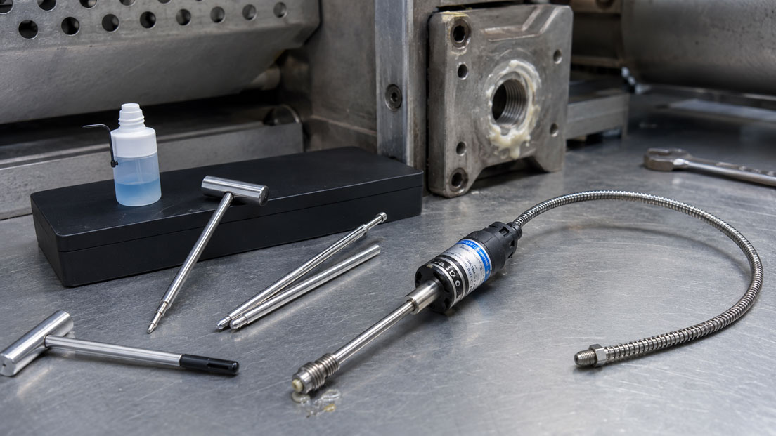
Depending on the version, a Dynisco cleaning tool kit may include:
- a thread cleaner or tap,
- a guide sleeve,
- a cleaning drill or sealing-seat cutter,
- a handle,
- a gauge plug,
- marking compound for checking the sealing surface.
Cleaning should preferably be carried out while the polymer is still semi-molten. The thread is cleaned first. The guided cleaning tool is then carefully rotated in the intended direction. It must not be tilted sideways or levered back and forth using excessive force.
The gauge plug indicates whether the guide bore and sealing surface are clear. The marking compound should be removed uniformly only from the designated 45° sealing surface. Contact on other surfaces may indicate residue, an incorrect bore depth or an incorrectly manufactured mounting hole.
The tool is intended for cleaning the mounting hole, not for working on the sensor diaphragm.
Inspecting the removed sensor for damage
Before storage or reinstallation, the sensor must be inspected carefully. At least the following points should be assessed:
- diaphragm free from dents, cracks and scratches,
- sealing edge not compressed or sheared,
- thread free from seizure marks and deformation,
- stem straight and mechanically undamaged,
- flexible capillary free from kinks, crushing or twisting,
- connector and cable undamaged,
- no leakage of filling fluid,
- plausible zero signal after temperature stabilisation.
A damaged process diaphragm must not be straightened, ground or polished. If visible damage, a significant zero-point shift or an abnormal shunt signal is detected, the sensor must be professionally inspected or replaced.
Preparing the thread and reinstalling the sensor
Before reinstallation, the sensor and mounting hole must have the same thread and connection design. Common versions include 1/2″-20 UNF and M18 × 1.5. Similar thread diameters are not automatically compatible.
Reinstallation is performed in the following sequence:
- Inspect the mounting hole and sealing surface using the gauge plug.
- Inspect the sensor tip and diaphragm for damage.
- Apply a small quantity of manufacturer-approved high-temperature anti-seize compound to the thread.
- Keep the sealing surface and diaphragm free from compound and contamination.
- Screw the sensor in straight by hand for several thread turns.
- Tighten the sensor to the specified torque using the spanner flats.
- Route the capillary and cable without mechanical stress.
- Check the electrical connection and pin assignment.
Excessive tightening torque does not improve sealing indefinitely. Instead, it increases the risk of thread seizure, stem deformation and future removal problems. The instructions for the specific sensor series and process connection are authoritative.
After heating and sufficient thermal stabilisation, the zero point, shunt function and measured value should be checked for plausibility. A zero adjustment may only be performed when the process is reliably depressurised.
Correctly storing and transporting the sensor
The sensitive diaphragm must be fitted with a suitable protective cap immediately after cleaning and cooling. The sensor should be stored in a dry location so that no load is applied to the stem, thread or capillary line.
Flexible connections must not be tightly coiled, kinked or used to carry the sensor. The electrical connector, type plate and calibration data should remain protected and clearly assigned to the sensor during storage.
Typical errors during removal and cleaning
| Error | Possible consequence | Correct measure |
|---|---|---|
| Unscrewing the sensor while the extruder is cold | The diaphragm adheres to the polymer and tears off | Heat the measuring point in a controlled manner and allow sufficient heat-soak time |
| Rotating the housing or connector | Internal connection or cable is damaged | Use only the designated spanner flats |
| Using a long lever or impact wrench | Stem, thread or capillary breaks | Stop removal if unusual resistance is encountered |
| Cleaning the diaphragm with a wire brush | The diaphragm is abraded or scratched | Wipe the hot sensor tip only with a soft cloth |
| Using the cleaning drill on the sensor diaphragm | Immediate and complete destruction of the sensor | Use the tool exclusively in the empty mounting hole |
| Reusing a contaminated mounting hole | The diaphragm is crushed during installation | Fully inspect the thread, guide bore and sealing surface |
| Applying excessive anti-seize compound | Compound reaches the sealing surface or enters the process | Apply only a thin layer to approved thread areas |
| Installing the sensor using excessive torque | Thread seizure and future removal problems | Comply with the specified tightening torque |
| Failing to use a protective cap | The diaphragm is damaged during storage or transport | Protect the sensor tip immediately after it has cooled |
Practical example: Stuck sensor at an extruder head
A melt pressure sensor at an extruder head is to be replaced as part of scheduled maintenance. The machine was shut down the previous day and has cooled completely. During the first removal attempt, the sensor does not move even when increased force is applied.
The service technician stops the attempt instead of extending the lever. The electrical connection is disconnected, the measuring point is heated in a controlled manner and sufficient heat-soak time is allowed after the material temperature has been reached. The system is then checked again to confirm that it is depressurised.
Using the correct spanner on the designated flats, the sensor can now be loosened slowly. The still-soft polymer residue is removed from the tip using a non-abrasive cloth. The diaphragm is undamaged, but the thread shows initial signs of seizure.
The empty mounting hole is cleaned using the Dynisco cleaning tool kit. The gauge plug initially indicates contact outside the designated sealing surface. After further cleaning, the contact area is distributed uniformly across the 45° seat.
The replacement sensor is installed with a thin layer of approved high-temperature anti-seize compound on the thread and tightened to the specified torque. After heating, the hot zero point is checked. This controlled procedure prevents damage to the sensor and reduces the risk of damaging the new sensor during installation.
Which products and tools are suitable?
Dynisco melt pressure sensors
The Dynisco melt pressure sensors category includes different sensor series for extrusion, injection moulding, compounding and other high-temperature applications.
When selecting a sensor, the pressure range, process temperature, stem length, thread, diaphragm material, output signal and existing evaluation electronics must be compatible.
Pressure transducer mounting-hole cleaning tool kit
The pressure transducer mounting-hole cleaning tool kit is used to remove polymer residue from the thread, guide bore and 45° sealing surface.
The included gauge plug can be used to check whether the mounting hole has been cleaned and manufactured correctly. Depending on the version, tools are available for 1/2″-20 UNF, M18 × 1.5 and other connection sizes.
Pressure transducer mounting-hole machining tool kit
The pressure transducer mounting-hole machining tool kit contains the drills, reamers and threading tools required to manufacture a new sensor mounting hole correctly.
The cleaning tool kit and machining tool kit perform different functions: one cleans an existing correctly manufactured hole, while the other is used to manufacture a new hole with the correct geometry or carry out professional reworking.
Conclusion: Never use force to remove a stuck melt pressure sensor
Solidified plastic melt can hold a melt pressure sensor so firmly that considerable forces act on the diaphragm, thread and stem during cold removal. Applying more torque is not the correct solution.
The measuring point must be completely depressurised and heated in a controlled manner to a suitable material temperature. The sensor must only be loosened using the designated spanner flats. The housing, cable and flexible capillary must not be subjected to torsional loads.
The diaphragm may only be cleaned using a soft, non-abrasive cloth. Drills, thread cleaners and sealing-seat cutters belong exclusively inside the empty mounting hole. Before reinstallation, the mounting hole, sealing surface, thread and condition of the sensor must be inspected completely.
Correct removal protects not only the existing sensor. It also prevents a contaminated or damaged mounting hole from destroying the replacement sensor during installation.
Frequently asked questions about removing melt pressure sensors
Can a melt pressure sensor be removed from a cold extruder?
This is generally not recommended. Solidified polymer can adhere to the diaphragm and damage or tear it off when the sensor is unscrewed. The measuring point should be heated in a controlled manner until the material is sufficiently soft.
How can I determine whether the process is genuinely depressurised?
The system must be depressurised according to the specified machine procedure and secured against renewed pressure build-up. An indication of 0 bar alone is not sufficient if blocked channels or trapped material plugs are possible.
May I rotate the electronics housing?
No. The spanner must be applied exclusively to the designated flats of the process connection. Rotating the housing can damage internal wires, the capillary or mechanical connections.
How should the diaphragm be cleaned?
Soft polymer residue can be removed carefully from the hot sensor tip using a soft, non-abrasive cloth. Scrapers, wire brushes, knives and abrasive tools must not contact the diaphragm.
Can the Dynisco cleaning drill be used on the sensor?
No. The cleaning tool kit is intended exclusively for the empty mounting hole. The thin process diaphragm would be damaged immediately by the tool.
What should be done if the thread has seized?
The removal attempt should be stopped before the stem or thread breaks. It may be necessary to remove the relevant machine component and loosen the connection under controlled workshop conditions.
Should installation compound be used?
A manufacturer-approved high-temperature anti-seize compound can be applied sparingly to the sensor thread. The sealing surface, diaphragm and process side must remain free from compound. The instructions for the relevant sensor series are authoritative.
Must the sensor be inspected after removal?
Yes. The diaphragm, thread, sealing edge, stem, capillary and electrical connection should be inspected. After reinstallation and at a stable operating temperature, at least the zero point and electrical test function should be checked for plausibility.