


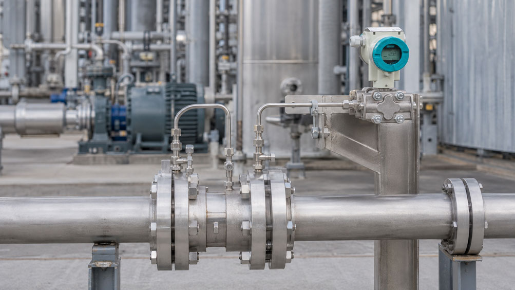
An orifice plate is intended to measure the flow rate in a pipeline. This quickly raises the question: How large should the orifice bore be? A smaller bore generates a higher differential pressure and therefore a stronger measuring signal. At the same time, however, flow velocity and permanent pressure loss increase.
The central sizing parameter is the beta ratio:
β = d / D
Where:
d= orifice bore diameter,D= internal diameter of the pipe.
For a pipe with:
D = 100 mm
and an orifice bore of:
d = 60 mm
the result is:
β = 60 / 100 = 0.60
This ratio directly influences the generated differential pressure, the flow conditions, the required measuring span of the differential pressure transmitter and the energy loss of the measuring point.
An orifice plate should therefore not be designed simply to produce the highest possible differential pressure. Instead, the objective is to achieve a sensible compromise between a sufficiently strong measuring signal, acceptable pressure loss, a suitable beta ratio, Reynolds number and the actually available upstream and downstream straight pipe runs.
For this purpose, ICS Schneider offers, among other products, the WIKA FLC-OP Orifice Plate as well as the FLC-FL Orifice Flange and FLC-AC Annular Chamber Orifice Plate. The generated differential pressure can, for example, be measured using the Siemens SITRANS P320 differential pressure transmitter. Further solutions can be found under Flow Measurement Technology at ICS Schneider.
Table of Contents
- How an orifice plate determines flow rate
- What does the beta ratio mean?
- Why β is not the area ratio
- How differential pressure and flow rate are related
- Basic equation for orifice plate measurement
- How the beta ratio influences differential pressure
- Distinguishing between differential pressure and permanent pressure loss
- Why permanent pressure loss causes energy costs
- Defining the differential pressure measuring span correctly
- Why low flow rates are difficult to measure
- Considering the Reynolds number
- Specifying density, viscosity and medium data correctly
- Special considerations for gases and steam
- Avoiding cavitation and vaporization in liquids
- Selecting pressure taps correctly
- Installing impulse lines correctly
- Considering upstream and downstream straight pipe runs
- Why the orifice edge and bore are metrologically relevant
- Installation direction and centering
- Selecting the correct differential pressure transmitter
- Why square-root extraction is required
- Practical example: influence of different beta ratios
- When a Venturi tube, nozzle or another differential-pressure primary element is more suitable
- Typical error patterns
- Systematically sizing an orifice plate
- Suitable components from ICS Schneider
- Conclusion
- FAQ
How an orifice plate determines flow rate
An orifice plate is a so-called primary flow element.
It has a defined opening whose diameter is smaller than the internal diameter of the pipe.
As the medium passes through the orifice plate, the available flow cross-section is reduced.
This increases the flow velocity
and causes the static pressure to fall.
Two pressures are measured upstream and downstream of, or in the region of, the orifice plate:
p1
and:
p2
This results in the differential pressure:
Δp = p1 − p2
This differential pressure contains the flow information
In simplified form:
Q ∝ √Δp
The flow rate is therefore not linear to the differential pressure, but proportional to its square root.
What does the beta ratio mean?
The beta ratio describes the relationship between the orifice bore and the internal pipe diameter:
β = d / D
Where:
d= diameter of the orifice bore,D= internal pipe diameter.
Example
Internal pipe diameter:
D = 100 mm
Orifice bore:
d = 50 mm
Then:
β = 0.50
A small β means
- strong restriction,
- high velocity in the orifice opening,
- high differential pressure,
- tendency towards higher permanent pressure loss.
A large β means
- less restriction,
- lower differential pressure,
- lower permanent pressure loss,
- greater demands on sensitive differential pressure measurement.
There is therefore no universally “best” beta ratio.
Why β is not the area ratio
A common mistake is to interpret the beta ratio directly as the ratio of the free cross-sectional areas.
Since the pipe and orifice cross-sections are circular:
A = π × d² / 4
The area ratio is therefore:
Aorifice / Apipe = β²
For β = 0.50
the free orifice area is therefore not 50 % of the pipe area, but:
0.50² = 0.25
or:
25 %
For β = 0.70
the area ratio is:
0.70² = 0.49
or approximately:
49 %
This quadratic relationship explains why even relatively small changes in the bore diameter can significantly change the differential pressure.
How differential pressure and flow rate are related
For orifice plate measurement, the fundamental relationship is:
Q ∝ √Δp
If the flow rate doubles
the differential pressure ideally increases to approximately:
2² = 4
or four times the original value.
If the flow rate is halved
the differential pressure falls to:
0.5² = 0.25
or one quarter of the original value.
This is particularly important when selecting the differential pressure transmitter.
Example
At maximum flow rate:
100 mbar Δp
At 50 % flow rate, ideally only:
25 mbar Δp
At 20 % flow rate:
4 mbar Δp
The lower the flow rate becomes, the more rapidly the available differential pressure signal decreases.
Basic equation for orifice plate measurement
For incompressible media, the volumetric flow rate can be described in simplified form by:
Q = C × ε × A0 / √(1 − β⁴) × √(2 × Δp / ρ)
Where:
Q= volumetric flow rate,C= discharge coefficient,ε= expansion factor, approximately 1 for liquids,A0= area of the orifice bore,β= beta ratio,Δp= measured differential pressure,ρ= density of the medium.
The discharge coefficient is not assumed arbitrarily, but depends, among other things, on:
- beta ratio,
- Reynolds number,
- pressure tapping arrangement,
- geometry of the differential-pressure primary element
.
For standards-compliant sizing
the corresponding relationships according to, for example:
ISO 5167-2
are used.
An orifice plate should therefore not be sized solely using a simplified Bernoulli equation if a defined measurement accuracy is required.
How the beta ratio influences differential pressure
The flow equation shows that, with the same:
- pipe diameter,
- medium,
- flow rate
a smaller orifice bore generates a significantly higher differential pressure.
In simplified form
with otherwise unchanged conditions:
Δp ∝ (1 − β⁴) / β⁴
The relationship is therefore strongly nonlinear.
For this reason, changing from
β = 0.70
to:
β = 0.50
is not a minor modification of the measuring point.
The resulting differential pressure can increase several times over.
Distinguishing between differential pressure and permanent pressure loss
The differential pressure measured across an orifice plate is not identical to the pressure permanently lost.
Directly downstream of the orifice plate
the static pressure drops sharply.
Further downstream, the flow expands again and part of the pressure is recovered.
The differential pressure Δp
is the pressure difference between the defined pressure taps used for flow measurement.
The permanent pressure loss
is instead the difference between:
static pressure well upstream of the measuring point
and:
remaining downstream pressure after flow recovery
.
Only the portion that is not recovered must be permanently supplied additionally by a pump, compressor or other pressure source.
Why permanent pressure loss causes energy costs
An orifice plate permanently removes mechanical energy from the flow.
In a continuously operated system, this energy must be supplied again by the pumping or compression equipment.
For a liquid, the additional hydraulic power can be approximated as
P = Δploss × Q
For the actual electrical drive power required, the efficiency of the pump or the overall system must also be taken into account.
Example
Permanent pressure loss:
30 kPa
Volumetric flow rate:
100 m³/h = 0.0278 m³/s
Hydraulic power loss:
P ≈ 30,000 Pa × 0.0278 m³/s
P ≈ 834 W
In continuously operated plants, this can result in significant energy consumption over the operating period.
Therefore
a particularly high differential pressure does not automatically improve the overall quality of the measuring point.
At the same time, it can increase operating costs.
Defining the differential pressure measuring span correctly
After the hydraulic sizing of the orifice plate, the differential pressure transmitter must be matched to the pressure span actually generated.
A typical design could, for example, result in:
Qmax = 100 m³/h
at:
Δpmax = 100 mbar
The transmitter must then reliably cover this range
An unnecessarily large range such as:
0 … 1,000 mbar
can result in only a small portion of the available measuring span being used.
A suitable:
0 … 100 mbar
range, or a correspondingly configurable differential pressure transmitter, makes much better use of the available signal.
At the same time, the static process pressure must be considered
A differential pressure transmitter may, for example, measure only:
100 mbar differential pressure
while both sides are simultaneously exposed to:
50 bar process pressure
.
The differential pressure range and the permissible static operating pressure are therefore two different specifications.
Why low flow rates are difficult to measure
Since:
Δp ∝ Q²
the measuring signal decreases very rapidly at low flow rates.
Example
If at 100 % flow rate:
100 mbar
is generated, the idealized relationship is:
| Flow rate | Differential pressure |
|---|---|
| 100 % | 100 mbar |
| 75 % | 56.25 mbar |
| 50 % | 25 mbar |
| 25 % | 6.25 mbar |
| 10 % | 1 mbar |
At 10 % flow rate
the transmitter therefore has to resolve only:
1 % of the maximum differential pressure
.
Large flow measuring ranges can therefore become challenging with a conventional orifice plate.
Considering the Reynolds number
The Reynolds number describes the ratio between inertial and viscous forces in the flow.
It can be expressed in simplified form as:
Re = ρ × v × D / μ
or:
Re = v × D / ν
Where:
ρ= density,v= mean flow velocity,D= internal pipe diameter,μ= dynamic viscosity,ν= kinematic viscosity.
Why is Re important?
The discharge coefficient of the orifice plate depends on the Reynolds number within certain ranges.
An orifice plate that performs well with:
water at 20 °C
may operate in a completely different flow regime with a highly viscous oil under otherwise similar geometric conditions.
Density and viscosity at operating temperature are therefore required for sizing.
Specifying density, viscosity and medium data correctly
For reliable orifice plate calculation, simply stating:
Medium = water
or:
Medium = air
is not always sufficient.
Depending on the application, the required information includes
- medium or composition,
- minimum, normal and maximum flow rate,
- operating pressure,
- operating temperature,
- density,
- viscosity,
- pipe material,
- internal pipe diameter.
For gases
pressure and temperature are particularly important because they determine the operating density.
The specification:
1,000 Nm³/h
is not identical to:
1,000 m³/h at operating conditions
.
Special considerations for gases and steam
For liquids, density can often be considered approximately constant at moderate pressure changes.
Gases and steam, however, are compressible.
An expansion factor is therefore considered in orifice plate measurement
In the flow equation:
ε
appears as a correction for expansion of the medium during the pressure drop.
For gases, the following must therefore additionally be considered
- absolute pressure,
- temperature,
- gas composition,
- isentropic exponent or corresponding fluid properties,
- compressibility.
For steam
it must additionally be clearly specified whether:
- saturated steam,
- superheated steam
is present.
For accurate mass flow measurement, pressure and temperature compensation may be required.
Avoiding cavitation and vaporization in liquids
A strong restriction creates very low local static pressures.
If the local pressure of a liquid falls below its vapor pressure, vapor bubbles can form.
If the pressure then rises again
these bubbles can collapse.
This process is known as:
cavitation
.
Possible consequences include
- noise,
- vibration,
- erosion,
- unstable measured values,
- damage to the pipe or orifice plate.
For hot liquids close to the boiling point, the available process pressure must therefore be considered particularly carefully.
Selecting pressure taps correctly
The measured pressure difference also depends on the positions at which the static pressure is tapped.
For standardized orifice plates, examples include
- corner taps,
- flange taps,
- other pressure tap arrangements defined by the relevant standard.
The calculation used must match the actual pressure tap arrangement.
A calculated orifice plate and a different pressure tapping arrangement
do not form an identical measuring point.
The primary element, pressure taps and calculation parameters must therefore be specified together.
Installing impulse lines correctly
Impulse lines are often installed between the pressure taps and the differential pressure transmitter.
They are also part of the measurement chain.
Errors can be caused, for example, by
- gas bubbles in liquid-filled impulse lines,
- condensate in gas lines,
- different liquid columns,
- blocked impulse lines,
- leaks,
- temperature differences.
For liquids
both impulse lines should, as far as possible, remain completely filled with liquid.
For gases
unwanted condensate should be prevented or deliberately drained.
For steam
defined condensate columns are typically established on both sides.
Asymmetrical impulse lines can create a zero-point error even if the orifice plate and transmitter themselves are functioning correctly.
Considering upstream and downstream straight pipe runs
The calculation models for standardized orifice plates assume defined flow conditions.
Strong unaccounted-for flow disturbances should therefore not occur directly upstream of the orifice plate.
Typical disturbances include
- pipe bends,
- T-pieces,
- reducers,
- partially closed valves,
- pumps,
- swirl.
The required straight pipe runs
depend, among other things, on:
- beta ratio,
- type of upstream fitting,
- arrangement of multiple bends,
- primary flow element used.
For this reason, a general statement such as:
10 D upstream and 5 D downstream are always sufficient
should not be used.
The actual required lengths must be determined for the specific geometry in accordance with the applicable standard or manufacturer calculation.
Why the orifice edge and bore are metrologically relevant
An orifice plate is not simply a metal plate with a hole drilled into it.
For a standards-compliant square-edged orifice plate, the following are defined or limited, among other things:
- bore diameter,
- edge geometry,
- plate thickness,
- surface condition,
- centering.
A damaged inlet edge
can change the discharge coefficient.
Problems can arise, for example, from:
- erosion,
- corrosion,
- deposits,
- mechanical damage.
During long-term operation, the condition of the primary measuring element should therefore also be considered.
Installation direction and centering
The orifice opening must be correctly centered relative to the pipe axis.
An accidentally eccentric conventional square-edged orifice plate
changes the intended flow conditions and can affect the measurement.
This must be distinguished from a deliberately designed:
eccentric orifice plate
which is specifically intended for certain applications.
The installation direction is also relevant
With a conventional square-edged orifice plate, the defined sharp inlet edge must face the intended direction of flow.
An orifice plate installed backwards can therefore cause a systematic measurement error.
Selecting the correct differential pressure transmitter
The orifice plate initially generates only a differential pressure.
This pressure must then be measured reliably.
The Siemens SITRANS P320 is designed, among other things, for differential pressure and flow measurement.
ICS specifies the following for the SITRANS P320, among other features
- differential pressure and flow measurement,
- accuracy up to
0.065 %, - HART communication,
- diagnostic functions according to NAMUR NE107,
- different differential pressure measuring spans,
- versions for high static process pressures.
Two pressure values must be considered separately when selecting the transmitter
differential pressure to be measured
and:
static line pressure
.
A small Δp range at a high pipeline pressure is a typical requirement for differential-pressure flow measurement.
Why square-root extraction is required
Differential pressure is proportional to the square of the flow rate:
Δp ∝ Q²
Conversely:
Q ∝ √Δp
If a transmitter interpreted Δp linearly as flow rate
the indicated value would be incorrect.
The square-root function must therefore be implemented either:
- in the differential pressure transmitter,
- in the PLC,
- in the process control system.
Example
50 % differential pressure does not correspond to:
50 % flow rate
but to:
√0.5 ≈ 0.707
or approximately:
70.7 % flow rate
.
During commissioning, it must therefore be clearly documented where the square-root extraction is performed.
Practical example: influence of different beta ratios
A water line has, in simplified form:
D = 100 mm
and is intended to carry approximately:
30 m³/h
.
For an approximate comparison, different beta ratios are considered.
| β | Bore at D = 100 mm | Δp tendency | Permanent pressure loss tendency |
|---|---|---|---|
| 0.40 | 40 mm | very high | very high |
| 0.50 | 50 mm | high | high |
| 0.60 | 60 mm | medium | medium |
| 0.65 | 65 mm | lower | lower |
| 0.70 | 70 mm | comparatively low | comparatively low |
This illustrates the fundamental trade-off
With:
β ↓
the differential pressure signal becomes larger.
At the same time, however, flow loading and permanent pressure loss increase.
With:
β ↑
the energy loss decreases.
The differential pressure transmitter must then reliably resolve smaller pressure differences.
The optimum orifice plate therefore results from the complete measuring point and not from an isolated selection of the bore diameter.
When a Venturi tube, nozzle or another differential-pressure primary element is more suitable
Orifice plates are widely used, robust and comparatively simple in design.
Their main disadvantage, however, is their relatively high permanent pressure loss.
If energy efficiency is particularly important
other primary flow elements may be more suitable.
These include, for example:
- Venturi tubes,
- flow nozzles,
- averaging Pitot tubes,
- cone flow meters.
Venturi tubes
provide significantly better pressure recovery than a conventional orifice plate due to their aerodynamically optimized expansion section.
Multi-hole orifice plates
can be of interest when only limited upstream and downstream straight pipe runs are available.
ICS offers, for example, the WIKA FLC-MP Multi-Hole Orifice Plate.
For highly viscous or solids-containing media
another differential-pressure principle, such as a wedge flow meter, may be more suitable.
An orifice plate is therefore not automatically the optimum differential-pressure element for every application.
Typical error patterns
| Observation | Possible cause | Recommended check |
|---|---|---|
| Differential pressure significantly higher than calculated | orifice bore too small, deposits or incorrect medium data | check bore, flow rate, density and contamination |
| Differential pressure significantly lower than calculated | orifice bore too large, bypass or incorrect pressure tapping | check geometry and impulse lines |
| Measured value is correct only at high flow rates | Δp too low at low flow rates | check transmitter range and turndown |
| Flow indication is also 50 % at 50 % Δp | square-root extraction missing | check transmitter or PLC configuration |
| Measured value changes after piping modification | flow profile changed | check upstream and downstream straight pipe runs |
| Measurement fluctuates downstream of a pipe bend | swirl or asymmetrical flow profile | evaluate upstream straight run and flow conditioner |
| Transmitter zero point shifts | different liquid columns in the impulse lines | check impulse lines and installation height |
| Measured value responds very slowly | impulse line partially blocked | check both differential-pressure lines |
| Plant pressure loss is higher than expected | β too small or orifice plate energetically unfavorable | calculate permanent pressure loss and evaluate alternative |
| Orifice plate produces different readings after long-term operation | erosion or deposits at the orifice edge | inspect the primary measuring element |
| Measured value changes significantly after replacing the orifice plate | different bore, edge or installation direction | check orifice plate identification and geometry |
| Liquid measurement causes noise and vibration | possible cavitation | check minimum pressure and vapor pressure of the medium |
Systematically sizing an orifice plate
- Define the medium completely: Specify liquid, gas or steam as well as its composition.
- Determine the flow range: Define minimum, normal and maximum flow rate.
- Check reference conditions: Clearly distinguish operating volume from standard volume for gases.
- Determine operating pressure: Specify minimum, normal and maximum pressure.
- Determine operating temperature: Define the temperature range of the measuring point.
- Determine fluid properties: Consider density and viscosity under operating conditions.
- Record pipe data: Determine nominal size, actual internal diameter, material and pipe condition.
- Evaluate Reynolds number: Check whether the selected orifice design operates within the appropriate range.
- Determine the beta ratio: Select a suitable bore diameter within the applicable calculation method.
- Define differential pressure: Generate a sufficiently large measuring signal without causing unnecessary pressure loss.
- Check permanent pressure loss: Consider energy demand and available process pressure.
- Check cavitation for liquids: Compare local minimum pressure with the vapor pressure.
- Select pressure tapping arrangement: Define a tapping arrangement compatible with the applicable standard and calculation.
- Check upstream flow conditions: Consider bends, valves, reducers and other disturbances.
- Define straight pipe runs: Determine the required upstream and downstream lengths according to the standard or manufacturer calculation.
- Select the orifice plate material: Consider pressure, temperature, corrosion and erosion.
- Select the differential pressure transmitter: Consider Δp measuring span and static process pressure separately.
- Plan impulse lines: Install them according to medium and physical state.
- Define square-root extraction: Specify whether the transmitter or control system performs the square-root calculation.
- Evaluate total uncertainty: Consider the primary element, transmitter, fluid data and installation conditions together.
Suitable components from ICS Schneider
WIKA FLC-OP Orifice Plate
The WIKA FLC-OP is designed as a primary flow element for liquids, gases and steam.
For conventional square-edged orifice plates, WIKA specifies, among other things:
- design according to
ISO 5167-2, - nominal sizes from
DN 50, - beta ratios depending on the design,
- different materials and flange versions,
- different pressure tapping arrangements and installation versions.
WIKA FLC-FL and FLC-AC
For measuring points with corresponding pressure tapping arrangements, the following are also available:
- FLC-FL Orifice Flanges,
- FLC-AC Annular Chamber Orifice Plates
.
Siemens SITRANS P320
The SITRANS P320 can measure the differential pressure generated by the orifice plate and evaluate it for flow measurement.
ICS specifies, among other things:
- differential pressure and flow measurement,
- accuracy up to
0.065 %, - HART communication,
- NAMUR NE107 diagnostics,
- different differential pressure measuring ranges,
- versions for high static process pressures.
WIKA FLC-MP Multi-Hole Orifice Plate
If only limited upstream and downstream straight pipe runs are available, the WIKA FLC-MP can be an alternative.
ICS specifies, among other things, for this version:
- four circularly arranged bores,
- use with limited straight pipe runs,
- suitability for liquids, gases and steam,
- repeatability of
0.1 %of flow rate.
Further solutions can be found under Flow Measurement Technology at ICS Schneider.
Conclusion
Sizing an orifice plate always involves a compromise between sufficiently high differential pressure and the lowest possible permanent pressure loss.
The beta ratio is the central geometric parameter
It is defined as:
β = d / D
and directly influences the degree of restriction.
Small beta ratios generate high differential pressures
This produces a strong and easily measurable signal, but at the same time increases permanent pressure loss.
Large beta ratios reduce pressure loss
The differential pressure becomes smaller, however, placing higher demands on the transmitter and signal processing.
Differential pressure and flow rate are not linear
The relationship is:
Q ∝ √Δp
Square-root extraction must therefore be taken into account in the measurement chain.
The Reynolds number is part of the sizing process
Density, viscosity, pipe diameter and flow velocity influence the valid operating range and the discharge coefficient.
Installation conditions can invalidate the calculation
Pipe bends, valves, swirl, incorrect pressure taps, damaged orifice edges or unsuitable impulse lines can cause systematic measurement errors.
Energy consumption is also part of instrument selection
In continuous operation, permanent pressure loss can result in costs over the years that are significantly higher than the cost of the measuring instrument itself.
For practical applications
Determine the medium and fluid properties → define operating pressure and temperature → define minimum, normal and maximum flow rates → determine the actual internal pipe diameter → evaluate Reynolds number → determine a suitable beta ratio → calculate differential pressure at Qmax → check permanent pressure loss and energy demand → consider cavitation or compressibility → define pressure taps and installation conditions according to the standard → size the differential pressure transmitter for Δp and static pressure → plan impulse lines correctly → define square-root extraction → evaluate total measurement uncertainty → verify the measuring point under actual operating conditions.
FAQ: Sizing an Orifice Plate Correctly
What is an orifice plate?
An orifice plate is a primary flow element with a defined cross-sectional restriction. The flow rate is determined from the differential pressure generated across this restriction.
What does the beta ratio of an orifice plate mean?
The beta ratio is the ratio between the orifice bore diameter and the internal pipe diameter: β = d / D.
Is β the ratio of the free cross-sectional areas?
No. β is a diameter ratio. For circular cross-sections, the area ratio is β².
What does β = 0.5 mean?
The orifice bore is 50 % of the internal pipe diameter. Its free area, however, is only 25 % of the pipe cross-sectional area.
What happens with a smaller beta ratio?
The restriction becomes stronger, differential pressure increases and permanent pressure loss generally also increases.
What happens with a larger beta ratio?
The restriction becomes smaller. As a result, differential pressure and permanent pressure loss decrease.
What is the optimum beta ratio?
There is no universal answer. It depends, among other things, on flow rate, pipe diameter, medium, Reynolds number, desired differential pressure, pressure loss and the applicable standard.
How are flow rate and differential pressure related?
For differential-pressure flow measurement, the fundamental relationship is Q ∝ √Δp.
Does differential pressure double when the flow rate doubles?
No. In an idealized relationship, doubling the flow rate results in approximately four times the differential pressure.
What does square-root extraction mean?
Square-root extraction means taking the square root of the differential pressure signal so that a signal proportional to flow rate is obtained.
Can the differential pressure transmitter perform the square-root extraction?
With suitable process transmitters, yes. Alternatively, the square-root function can be implemented in the PLC or process control system.
What is the difference between differential pressure and permanent pressure loss?
The differential pressure is measured to determine the flow rate. Part of the pressure is recovered downstream. Only the remaining pressure difference represents the permanent pressure loss.
Why is permanent pressure loss important?
Because pumps or compressors must continuously supply the energy associated with this lost pressure.
Why does a small orifice bore cause greater energy loss?
The stronger restriction increases flow velocity, turbulence and irreversible losses.
How is the beta ratio calculated?
Using β = d / D, where d is the orifice bore diameter and D is the internal pipe diameter.
Which pipe diameter is used for β?
The actual internal pipe diameter defined for the calculation is decisive, not simply the nominal size DN.
Why must the Reynolds number be considered?
Because the flow behavior and the discharge coefficient of the orifice plate depend on it.
Which fluid properties are required for orifice plate calculation?
In particular, density and viscosity under actual operating conditions. For gases, additional thermodynamic properties are required.
Can I size an orifice plate using only nominal pipe size and flow rate?
No. For reliable sizing, pressure, temperature, medium properties, internal pipe diameter and installation conditions are also required.
What must additionally be considered for gases?
Among other things, compressibility, operating pressure, temperature and the expansion factor.
What must be considered for steam?
In addition to pressure and temperature, it must be defined whether saturated or superheated steam is present. Pressure and temperature compensation may be required for accurate mass flow measurement.
Can an orifice plate cause cavitation?
Yes. If the local static pressure of a liquid falls below its vapor pressure, vapor bubbles can form and cavitation can occur.
What are pressure taps?
They are defined locations upstream and downstream of, or in the region of, the orifice plate where the static pressures required for differential pressure measurement are taken.
Why must the pressure taps match the calculation?
Because the measured differential pressure depends on their position and the calculation coefficients apply to defined tapping arrangements.
Why are impulse lines important?
They transmit the pressure from the tapping points to the differential pressure transmitter. Gas bubbles, condensate, blockages or different liquid columns can cause measurement errors.
Why does an orifice plate require straight upstream pipe runs?
To ensure that a sufficiently defined flow profile is present at the orifice plate, as assumed by the calculation method.
How long must the upstream straight pipe runs be?
This depends, among other things, on the beta ratio and the upstream pipe fittings. The required values must be determined for the specific installation in accordance with the applicable standard or manufacturer calculation.
Are 10 D upstream and 5 D downstream always sufficient?
No. Such general values are not valid for every piping geometry.
Can a pipe bend be located directly upstream of the orifice plate?
This can significantly influence the flow profile. Whether the available straight pipe run is sufficient must be evaluated for the specific installation.
Why is the sharp orifice edge important?
The defined edge influences flow separation and therefore the discharge coefficient. Damage, erosion or deposits can change the measurement.
Can an orifice plate be installed backwards?
Yes. With a conventional square-edged orifice plate, the intended inlet edge must face the correct direction of flow.
Must the orifice plate be centered?
Yes. Unintentional eccentricity can alter the flow conditions and therefore affect the measured value.
What is an eccentric orifice plate?
An eccentric orifice plate is a deliberately asymmetrical special design for specific media and applications. It must not be confused with a standard orifice plate that has accidentally been installed off-center.
What is a multi-hole orifice plate?
A multi-hole orifice plate uses several openings instead of one central bore and can, for example, offer advantages where straight pipe runs are limited.
When is a Venturi tube better than an orifice plate?
If low permanent pressure loss is particularly important, a Venturi tube can be advantageous despite its higher initial cost.
Which transmitter is suitable for an orifice plate?
A suitable differential pressure transmitter whose measuring span matches the generated Δp and whose permissible static pressure is suitable for the process pressure.
Can the Siemens SITRANS P320 be used for orifice plate measurements?
Yes. The SITRANS P320 is designed, among other things, for differential pressure and flow measurements.
What accuracy does ICS specify for the SITRANS P320?
ICS specifies an accuracy of up to 0.065 % for the process transmitter, depending on the version and measuring task.
What is the WIKA FLC-OP?
The FLC-OP is an orifice plate used as a primary flow element for liquids, gases and steam.
According to which standard can the WIKA FLC-OP be designed?
For conventional square-edged orifice plates, WIKA specifies, among other standards, ISO 5167-2.
Where can I find the WIKA FLC-OP at ICS Schneider?
Further information is available under WIKA FLC-OP, FLC-FL and FLC-AC at ICS Schneider.
Where can I find the Siemens SITRANS P320?
Further information is available under Siemens SITRANS P320 at ICS Schneider.
Where can I find further flow measurement technology?
An overview is available under Flow Measurement Technology at ICS Schneider.