


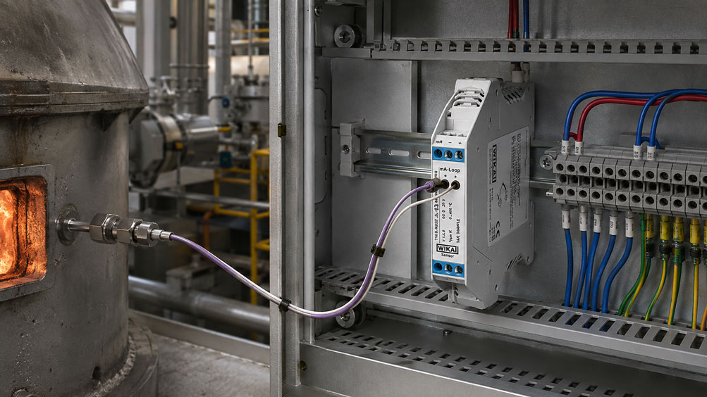
A Type K thermocouple measures, for example:
500 °C
in the process and is connected several meters away to a PLC or temperature transmitter. Along the way, the two thermocouple wires are transitioned to standard copper conductors. Electrically, there is continuity, the polarity is correct, and yet the temperature measurement shows a systematic error.
The cause is often not the thermocouple itself, but the reference junction or cold junction of the measuring chain.
A thermocouple does not generate a voltage that depends solely on the temperature of its measuring tip. The decisive factor is the temperature difference between the measuring junction and the reference junction. Therefore, the temperature at the point where the thermocouple materials transition to the copper conductors of the measuring electronics must be known.
The transition to copper is not fundamentally prohibited. What matters is that both transition points are thermally defined and that their temperature is correctly taken into account by the cold junction compensation. If the transition occurs at a different location from the actually compensated reference junction, systematic measurement errors will result.
In practice, this usually means that the thermocouple is routed with thermocouple, extension or compensating cable suitable for the thermocouple type all the way to the thermocouple input of the transmitter, controller or PLC module. Only there is the defined reference junction located. A temperature transmitter then performs linearization and cold junction compensation and can forward the signal, for example, as a robust 4 … 20 mA signal over standard copper cable.
For this purpose, ICS Schneider offers, among other products, Thermocouples as well as Temperature Transmitters and Accessories. A suitable example for directly connecting standard thermocouples is the WIKA Type T16 Temperature Transmitter. Further solutions can be found under Temperature Measurement Technology at ICS Schneider.
Table of Contents
- Why a thermocouple requires a reference junction
- Understanding the Seebeck effect and thermoelectric voltage
- Why thermocouple tables are referenced to 0 °C
- What is the cold junction?
- How cold junction compensation works
- What happens when transitioning to copper?
- Why copper does not automatically cause a measurement error
- When the transition to copper actually becomes problematic
- Distinguishing thermocouple, extension and compensating cables
- Why both connection terminals should have the same temperature
- Avoiding temperature gradients in the control cabinet
- Using a temperature transmitter close to the sensor
- Connecting a thermocouple directly to a PLC
- Using thermocouple connectors and intermediate terminals correctly
- Do not reverse polarity
- Practical example: incorrect copper transition
- Systematically checking the measuring chain
- Simulating the thermocouple input with a calibrator
- Typical error patterns
- Correctly designing a thermocouple measuring chain
- Suitable products from ICS Schneider
- Conclusion
- FAQ
Why a thermocouple requires a reference junction
A thermocouple consists of two conductors made of different metallic materials.
For a Type K thermocouple, for example, these are the defined thermocouple alloys used for that type.
The two conductors are electrically connected at the measuring junction.
The thermocouple does not measure absolute temperature
Its electrical signal is generated by the temperature conditions along the two different conductors.
For practical temperature measurement, the decisive relationship is therefore:
temperature of the measuring junction
in relation to:
temperature of the reference junction
.
If the measuring device knows only the thermoelectric voltage but not the temperature of the reference junction, the temperature at the measuring junction cannot be determined unambiguously.
Understanding the Seebeck effect and thermoelectric voltage
The operating principle of a thermocouple is based on the Seebeck effect.
If an electrical circuit consists of different metallic conductors and temperature differences exist, a thermoelectric voltage is generated.
In simplified form
UTC = f(Tmeas, Tref)
Where:
UTC= measured thermoelectric voltage,Tmeas= temperature at the measuring junction,Tref= temperature of the reference junction.
Since the thermoelectric behavior is not perfectly linear across the entire temperature range, measuring devices use defined characteristic curves or tables for the individual thermocouple types.
The correct thermocouple type must therefore also be configured
A Type K signal, for example, must not be evaluated using the characteristic curve of a:
- Type J,
- Type T,
- Type N
thermocouple.
The voltage may be similarly small, but the corresponding temperature values are different.
Why thermocouple tables are referenced to 0 °C
Standardized thermoelectric voltage characteristic curves are referenced to a defined reference temperature.
Traditionally, this is:
0 °C
In practice, however, a measuring device is normally not at 0 °C
The connection terminals may, for example, be at:
24 °C
.
The thermoelectric voltage at the input therefore does not directly correspond to the voltage that the same thermocouple would generate relative to a 0 °C reference junction.
The measuring device must therefore perform a mathematical correction
In simplified form:
measured thermoelectric voltage + correction for terminal temperature → thermoelectric voltage referenced to 0 °C
Only then is this voltage converted into the actual process temperature using the thermocouple characteristic curve.
What is the cold junction?
The term:
cold junction
is historical and can be misleading.
The reference junction does not actually have to be cold.
It may, for example, be at
20 °C
30 °C
or even significantly higher.
The important factor is not that it is cold, but that its temperature is known.
The technically more precise term is therefore:
reference junction
.
In modern devices
this reference junction is usually located at the:
- thermocouple input of a temperature transmitter,
- thermocouple input of a controller,
- terminal block of a PLC thermocouple input card,
- thermocouple connection of a measuring instrument.
How cold junction compensation works
A modern thermocouple measuring device normally contains an additional temperature sensor close to its input terminals.
This may, for example, be a:
- resistance temperature sensor,
- thermistor,
- integrated semiconductor temperature sensor.
The measuring device uses this to determine the temperature of its reference junction
and calculates the corresponding correction voltage.
In simplified form, the measuring chain operates as follows:
measure thermoelectric voltage → detect terminal temperature → compensate reference junction → linearize characteristic curve → display temperature
For this calculation to work
the temperature sensor must measure the temperature of the actual transition points as accurately as possible.
This is one of the most important practical sources of error.
What happens when transitioning to copper?
At the latest inside a measuring device, the thermocouple signal is transferred to normal metallic conductors or copper structures.
A transition to copper is therefore technically unavoidable.
However, both thermocouple conductors must be considered
At the transition, for example, the following junctions are created:
thermocouple material A → copper
and:
thermocouple material B → copper
Together, these two transitions form the reference junction.
The decisive condition is
that both transitions are at approximately:
the same temperature
.
In addition, this temperature must be correctly detected by the measuring device or external compensation system.
Why copper does not automatically cause a measurement error
It is often stated in simplified form:
Never connect a thermocouple to copper
This statement is helpful for practical wiring, but it is not physically complete.
According to the law of intermediate metals
an additional metal can be introduced into a thermocouple circuit without changing the resulting thermoelectric voltage, provided that the newly created junctions are at the same temperature.
This means:
TC+ → Cu
and:
TC− → Cu
are not automatically problematic.
Problems arise
when:
- the two transition points have different temperatures,
- the internal cold junction compensation measures at a different location,
- a temperature gradient exists between the transition point and the measuring device.
The decisive question is therefore not “Is there copper?”, but rather “Where does the transition to copper occur and which temperature does the cold junction compensation use?”
When the transition to copper actually becomes problematic
A typical error occurs with the following configuration:
thermocouple → compensating cable → standard terminal block → copper cable → PLC thermocouple input
Assume that the terminal block is at:
35 °C
and the thermocouple input of the PLC is at:
25 °C
.
The actual reference junction is then already located at the copper terminal block
The PLC, however, measures its terminal temperature at:
25 °C
and assumes that this is exactly where the thermocouple material ends.
This assumption is incorrect.
This causes a systematic measurement error
The exact magnitude depends on the thermocouple type and on the temperature difference between the actual and assumed reference junction.
Distinguishing thermocouple, extension and compensating cables
A thermocouple should not simply be extended using normal copper cable.
Different cable types are available for longer measuring distances.
| Cable type | Principle | Typical use |
|---|---|---|
| Thermocouple cable | Conductors made from the actual thermocouple materials | direct measuring circuit |
| Extension cable | thermoelectric properties corresponding to the respective thermocouple type | extension from the measuring point to the reference junction |
| Compensating cable | substitute alloys with defined similar thermoelectric behavior | cost-effective extension within the specified temperature range |
| Copper cable | no characteristic curve corresponding to the thermocouple type | only after the defined reference junction or after signal conversion |
It is important to note
that extension and compensating cables are thermocouple-type-specific.
A cable for:
Type K
must therefore not automatically be used for:
Type J
.
The permissible temperature range of the cable and its insulation must also be taken into account.
Why both connection terminals should have the same temperature
Cold junction compensation ideally assumes that both thermocouple connections are located within an isothermal region.
This means:
Tterminal+ ≈ Tterminal−
Why is this important?
If one terminal is, for example, at:
25 °C
and the other at:
30 °C
there is no longer one clearly defined reference junction temperature.
The internal compensation cannot fully correct this spatial temperature difference.
Good measuring devices therefore try to
- position the thermocouple terminals close together,
- thermally couple them,
- shield them from rapid environmental temperature changes.
Avoiding temperature gradients in the control cabinet
A PLC thermocouple input card can be metrologically sound and still produce incorrect readings if strong temperature gradients occur around its terminal area.
Typical causes include
- power contactors directly next to the TC module,
- power supplies with high heat dissipation,
- frequency converters,
- direct sunlight on a control cabinet,
- cold supply air from a fan,
- warm air rising from a device mounted below,
- frequent opening of the control cabinet door.
Particularly unfavorable
is an air flow that heats or cools only one side of the terminal block.
Then:
TC+
and:
TC−
can reach different temperatures.
For good cold junction compensation, therefore, not only the accuracy of the internal temperature sensor is important, but also a terminal area that is as thermally homogeneous as possible.
Using a temperature transmitter close to the sensor
For long cable runs, it can be advantageous to convert the thermocouple signal into a standard signal close to the sensor.
The measuring chain can then be, for example:
thermocouple → short TC cable → temperature transmitter → 4 … 20 mA → PLC
The temperature transmitter performs
- measurement of the thermoelectric voltage,
- cold junction compensation,
- linearization of the thermocouple type,
- conversion into a robust output signal.
From the transmitter onward, standard copper cable can be used for the 4 … 20 mA signal.
This reduces several typical sources of error
Thermocouple millivolt signals no longer need to be transmitted over long distances.
In addition, the defined reference junction is located directly at the transmitter.
Connecting a thermocouple directly to a PLC
Many PLC systems have dedicated thermocouple input cards.
These can include internal cold junction compensation.
With internal compensation
the cable corresponding to the thermocouple type should generally be routed all the way to the designated input terminals.
The reference junction is then located where:
thermocouple/compensating material → input terminal
transitions.
The temperature of the terminal area is measured by the module’s internal reference sensor.
An early transition to copper shifts the actual reference junction
and can therefore make the internal compensation ineffective.
Some systems also allow external compensation
In this case, the temperature of an external reference junction is measured separately, for example using a Pt100, and supplied to the PLC as a reference value.
The exact wiring must comply with the documentation of the respective input module.
Using thermocouple connectors and intermediate terminals correctly
Connectors and terminal blocks can also introduce additional junctions into the measuring chain.
Special thermocouple connectors are therefore available
with contact materials matched to the respective thermocouple type.
Thermocouple-compatible terminal blocks and connection components can also be used.
A standard copper terminal block, however, is critical
if it interrupts the thermocouple cable and there is still a significant cable run to the actual cold junction compensation point.
An intermediate terminal is therefore not merely a mechanical wiring detail; it can change the thermal definition of the entire measuring chain.
Do not reverse polarity
In addition to cold junction compensation, polarity is one of the most common sources of error with thermocouples.
If positive and negative are reversed
the thermoelectric voltage is evaluated with the wrong polarity.
Depending on:
- process temperature,
- terminal temperature,
- thermocouple type
this can lead to obviously incorrect or sometimes surprisingly plausible but wrong temperature readings.
Particularly difficult to detect
is a double polarity reversal.
If the cable is reversed at two points, the measurement can appear plausible under certain operating conditions.
A systematic check of the complete conductor assignment is therefore better than evaluating only the displayed temperature value.
Practical example: incorrect copper transition
A machine is equipped with a Type K thermocouple.
The measuring point is at:
400 °C
.
The compensating cable ends in an intermediate terminal box at a standard copper terminal block.
From the terminal box, copper cables continue for another:
15 m
to the PLC thermocouple input card.
Temperature in the intermediate terminal box
45 °C
Temperature at the PLC input
25 °C
The problem
The actual transition from thermocouple materials to copper already takes place at:
45 °C
.
However, the PLC performs its internal cold junction compensation based on its own terminal area at approximately:
25 °C
.
The actual and assumed reference junction therefore differ by:
20 K
The technically correct solution
is, for example, to route the appropriate Type K compensating or extension cable all the way to the thermocouple input of the PLC.
Alternatively, a suitable temperature transmitter can already be installed in the intermediate terminal box:
Type K → temperature transmitter → 4 … 20 mA → copper cable → PLC
This ensures that the transition to copper is located either directly at the correctly compensated PLC reference junction or downstream of a completed thermocouple signal conversion.
Systematically checking the measuring chain
If a thermocouple produces a suspicious temperature value, the sensor should not immediately be replaced.
The entire measuring chain must be considered.
- Identify the thermocouple type: Clearly determine whether it is Type K, J, T, N, E, R, S or B.
- Check configuration: Is the same thermocouple type configured in the transmitter, controller or PLC input?
- Check polarity: Trace the positive and negative conductors throughout the entire wiring route.
- Check cable type: Is the correct thermocouple, extension or compensating cable being used?
- Look for intermediate terminals: Check whether a transition to copper occurs anywhere before the TC input.
- Determine the reference junction: Where do the thermocouple materials actually end?
- Determine the cold junction compensation: Where does the device measure its reference temperature?
- Check temperature gradients: Inspect heaters, fans or warm air flows around the terminal area.
- Check connectors: Are thermocouple plugs and sockets designed for the correct thermocouple type?
- Simulate the signal: Test the thermocouple input using a suitable calibrator.
- Test the sensor separately: Only then evaluate the actual sensor as a possible source of error.
Simulating the thermocouple input with a calibrator
A thermocouple calibrator can generate the thermoelectric voltage corresponding to a defined thermocouple type.
This allows verification of whether the:
- PLC input,
- temperature transmitter,
- controller,
- display
are working correctly.
However, the reference junction must also be considered during simulation
There are essentially two different test approaches:
simulate thermocouple temperature including CJC
or:
inject pure mV signal and evaluate CJC separately
A modern calibrator can perform cold junction compensation itself
or, depending on the test setup, operate with a manually entered reference temperature.
If CJC is combined incorrectly on the calibrator and device sides, both devices can be individually correct and still produce an incorrect comparison value.
Further information can also be found in the ICS technical article Simulating Thermocouples: Correctly Testing Type K, J and N in Measuring Chains.
Typical error patterns
| Observation | Possible cause | Recommended check |
|---|---|---|
| Constant temperature offset | incorrectly defined reference junction | check copper transition and CJC position |
| Error changes with control cabinet temperature | cold junction compensation or temperature gradient | observe terminal temperature |
| Measured value changes when a power supply is switched on | local heating of the TC terminals | check thermal arrangement in the control cabinet |
| Measured value changes when the control cabinet is opened | airflow affects the reference junction | thermally stabilize the terminal area |
| Measured value is correct only at a certain room temperature | early transition to copper | trace the cable route to the TC input |
| Temperature moves in the wrong direction when heated | polarity reversed | check positive/negative conductors |
| Measurement no longer works correctly after cable replacement | incorrect compensating cable | compare cable type with thermocouple type |
| Several channels show a similar offset | shared CJC or module problem | check terminal temperature and module diagnostics |
| Only one channel drifts | terminal, contact or cable problem on that channel | check wiring and contact points |
| Measured value jumps when connector is moved | contact problem or unsuitable connector | check thermocouple connector and contacts |
| Calibrator is correct, real sensor is not | sensor, compensating cable or intermediate connection | check measuring chain section by section |
| Sensor and PLC are individually correct, but overall measurement is wrong | error in transition points or cold-junction concept | document the complete cable route |
Correctly designing a thermocouple measuring chain
- Determine the temperature range: Define minimum, normal and maximum temperature.
- Select the thermocouple type: Choose Type K, J, T, N or another type to suit the temperature and atmosphere.
- Define the measuring point: Specify installation position, insertion depth and mechanical design.
- Plan the cable route: Determine the distance between sensor and evaluation electronics.
- Select the correct extension: Use thermocouple, extension or compensating cable suitable for the thermocouple type.
- Minimize intermediate terminals: Avoid unnecessary material transitions.
- Use thermocouple-compatible connectors: Select contact materials matching the sensor type.
- Define the reference junction: Specify where the transition to the copper side of the electronics occurs.
- Define the CJC: Select internal or external cold junction compensation according to the measuring chain.
- Thermally stabilize the terminals: Keep heat sources and airflow away from the TC connection.
- Consider a temperature transmitter: For long or interference-prone cable runs, consider signal conversion close to the sensor.
- Document polarity: Clearly identify positive and negative conductors throughout the entire route.
- Configure the measuring device: Set the correct thermocouple type and measuring range.
- Simulate the measuring chain: Check the input and cold junction compensation during commissioning.
- Document the measuring point: Record sensor, cable type, terminals, CJC and evaluation device.
Suitable products from ICS Schneider
ICS Thermocouples
ICS Schneider offers Thermocouples in various industrial designs.
These include, among others:
- thermocouples with connection head,
- mineral-insulated thermocouples,
- measuring inserts,
- special designs,
- precision thermocouples.
WIKA Type T16 Temperature Transmitter
The WIKA Type T16 is specifically designed for thermocouple applications.
ICS and WIKA specify, among other things:
- connection of all standard thermocouples,
- head-mounted and DIN-rail versions,
- configurable sensor type and measuring range,
- 4 … 20 mA output,
- sensor break and measuring range monitoring,
- high immunity to electromagnetic interference.
Why a transmitter is useful for this application
The thermocouple cable can be routed directly to the transmitter.
There:
thermoelectric voltage + reference junction temperature
are evaluated.
A standardized:
4 … 20 mA
signal is then transmitted.
This allows the remaining cable run to be implemented using standard industrial copper cable.
Temperature Calibrators
For systematic testing of thermocouple measuring chains, ICS Schneider also offers Temperature Calibrators.
Depending on the device, these can simulate thermocouples or corresponding electrical sensor signals and verify measuring chains.
Further products can be found under Temperature Measurement Technology at ICS Schneider.
Conclusion
Cold junction compensation is one of the most important fundamentals of correct thermocouple measurement.
A thermocouple does not measure absolute temperature
Its thermoelectric voltage depends on the measuring junction and the reference junction.
The reference junction temperature must therefore be known
Modern measuring devices detect the temperature in the region of their thermocouple terminals and correct the measured thermoelectric voltage accordingly.
The transition to copper is not fundamentally wrong
However, it must take place at a thermally defined point whose temperature is actually used for cold junction compensation.
An early transition to copper can make the internal CJC ineffective
If the transition to copper already takes place in a remote terminal box while the PLC compensates its own terminal temperature, the actual and assumed reference junctions do not coincide.
Compensating and extension cables extend the thermal reference
They allow the defined transition to be shifted to the actual thermocouple input.
The terminal temperature itself must also be controlled
Warm power supplies, power electronics, fans and other local heat sources can impair the accuracy of an otherwise correctly designed measuring chain.
A temperature transmitter close to the sensor simplifies long measuring distances
After thermocouple evaluation, cold junction compensation and linearization, a robust 4 … 20 mA signal can, for example, be transmitted over standard copper cable.
For practical applications
Determine the thermocouple type → use the correct thermocouple, extension or compensating cable → maintain correct polarity throughout → avoid unnecessary intermediate terminals → identify the actual transition to copper → place the reference junction and CJC sensor at the same location → keep the terminal area thermally homogeneous → for long cable runs, consider a transmitter close to the sensor → configure the correct thermocouple type in the measuring device → simulate the measuring chain using a suitable calibrator → only then evaluate the sensor, cable and electronics separately.
FAQ: Cold Junction Compensation for Thermocouples
What is cold junction compensation in a thermocouple?
Cold junction compensation takes the temperature of the reference junction into account so that the actual temperature at the measuring junction can be determined from the measured thermoelectric voltage.
Why does a thermocouple require cold junction compensation?
Because a thermocouple does not measure absolute temperature. It generates a thermoelectric signal that depends on the temperature difference between the measuring and reference junctions.
Does the cold junction have to be at 0 °C?
No. Modern measuring devices measure the actual reference junction temperature and mathematically reference the signal to the standardized 0 °C reference.
Why is it called the cold junction?
The term is historical. The technically more accurate term is reference junction. It does not actually have to be cold.
Where is the cold junction located in a temperature transmitter?
It is typically located in the area of the thermocouple connection terminals, whose temperature is measured or compensated by the device.
Can a thermocouple be connected to copper cable?
Yes, but the transition to copper must occur at the defined reference junction or otherwise be correctly compensated.
Why is it nevertheless recommended not to extend thermocouples using copper cable?
Because an arbitrary transition to copper moves the actual reference junction to an uncontrolled location and can therefore cause a systematic measurement error.
What does the law of intermediate metals state?
An additional metal generally does not change the resulting thermoelectric voltage if the newly created junctions are at the same temperature.
Why should both thermocouple terminals be at approximately the same temperature?
Only then can one common reference junction temperature be meaningfully used for cold junction compensation.
Can a fan affect thermocouple measurement?
Yes. Airflow can create temperature gradients at the terminal block and thereby impair cold junction compensation.
Can a power supply next to a thermocouple input card cause a measurement error?
Yes. Its heat dissipation can heat the terminal area unevenly and thereby cause an additional CJC error.
What is a compensating cable?
A compensating cable uses defined substitute alloys with thermoelectric properties that correspond sufficiently closely to the respective thermocouple characteristic within a specified temperature range.
What is an extension cable?
An extension cable has thermoelectric properties corresponding to the respective thermocouple type within the intended range and extends the thermocouple circuit to the reference junction.
Can Type K compensating cable be used for Type J?
No. The cable must match the thermocouple type being used.
Can I use standard terminal blocks?
Standard copper terminals can be problematic if the thermocouple materials end there and the actual cold junction compensation is located only at a remote measuring device.
What are thermocouple connectors?
Thermocouple connectors are plug connections whose contact materials are designed for the respective thermocouple type.
What happens if thermocouple polarity is reversed?
The thermoelectric voltage is evaluated with the wrong polarity, which can result in significantly incorrect temperature readings or readings that move in the wrong direction.
Can a PLC measure a thermocouple directly?
Yes, provided it has a dedicated thermocouple input module with suitable linearization and cold junction compensation.
How should a thermocouple be connected to a PLC with internal CJC?
The appropriate thermocouple, extension or compensating cable should generally be routed all the way to the designated thermocouple terminals of the module.
What is external cold junction compensation?
In this case, the defined reference junction is located outside the measuring device and its temperature is measured separately, for example using a Pt100.
Why is a temperature transmitter close to the thermocouple useful?
It performs cold junction compensation and linearization close to the sensor and then transmits a more robust standard signal such as 4 … 20 mA.
Can standard copper cable be used after a temperature transmitter?
Yes. After conversion to, for example, 4 … 20 mA, the signal is no longer the original thermocouple millivolt signal.
How can cold junction compensation be tested?
Using a suitable thermocouple calibrator and a controlled test setup, it can be verified whether the input, reference junction temperature and linearization work correctly together.
Why can thermocouple simulation be incorrect even though both devices are working properly?
If the calibrator and device apply cold junction compensation differently or twice, the test setup no longer corresponds to the intended measuring chain.
Which thermocouple types does the WIKA T16 support?
The WIKA T16 is designed for the connection of all standard thermocouples and can be configured accordingly.
Where can I find the WIKA T16 at ICS Schneider?
Further information is available under WIKA Type T16 Temperature Transmitter at ICS Schneider.
Where can I find thermocouples at ICS Schneider?
An overview is available under Thermocouples at ICS Schneider.
Where can I find further temperature measurement technology?
Further solutions can be found under Temperature Measurement Technology at ICS Schneider.