


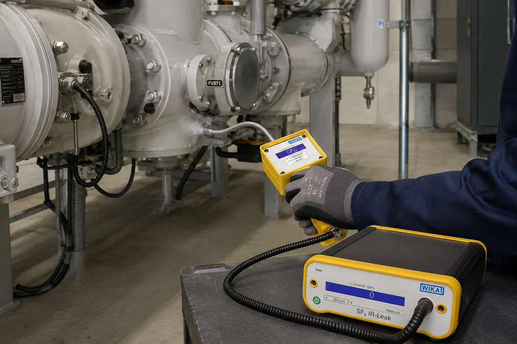
During SF₆ leak detection, the cause initially seems obvious: The probe is held near a fitting and the detector responds. A few seconds later, the signal decreases again. At a neighbouring connection, it rises once more, and eventually the instrument appears to respond almost everywhere in the room.
This behaviour does not automatically mean that the leak detector is defective. SF₆ that has already been released can spread through the surrounding air and increase the background concentration. If the search is then continued at high sensitivity, the instrument detects not only the actual leak plume but also gas that is already present in the room.
The measuring distance, movement speed of the probe, air currents, ventilation, contaminated filters and an unsuitable zero adjustment also influence leak detection. For reproducible results, a distinction must therefore be made between the general SF₆ background concentration and the local concentration directly at a leak.
Suitable instruments can be found in the ICS category SF₆ Detection Instruments. Further devices and components for filling, recovery, analysis and monitoring are grouped under SF₆ Gas Solutions.
Table of Contents
- What does an SF₆ leak detector measure?
- Distinguishing between qualitative and quantitative leak detection
- Why does the background concentration increase?
- Correctly performing the zero adjustment
- Selecting the appropriate sensitivity
- Maintaining the correct measuring distance and sniffing speed
- How does an SF₆ gas plume form?
- Accounting for ventilation and air movement
- SF₆ is heavier than air: What does this mean in practice?
- Checking the probe tip and filter
- Correctly assessing cross-sensitivities
- Performing a functional test before leak detection
- Systematically narrowing down the leak location
- When is quantitative assessment appropriate?
- Systematic diagnostic procedure for fluctuating readings
- Practical example: Leak detection after SF₆ refilling
- Typical errors during SF₆ leak detection
- What should be included in the documentation?
- Which products and solutions are suitable?
- Conclusion
- Frequently asked questions
What does an SF₆ leak detector measure?
An SF₆ leak detector does not directly detect a hole or a damaged seal. It detects SF₆, or the resulting change in the sensor signal, in the surrounding air drawn into the instrument.
With a sniffing leak detector, ambient air is drawn in through the probe tip and transported to the sensor. If SF₆ is present in this air, the instrument responds with:
- a concentration value,
- an audible signal,
- a visual indication
- or a combination of these signals.
The signal therefore does not depend exclusively on the size of the actual leak. The decisive factor is how much escaping SF₆ actually reaches the probe tip at the time of measurement.
A small leak can generate a clear signal when the probe is positioned optimally. A larger leak, by contrast, may be difficult to locate if strong air movement immediately disperses the escaping gas.
Distinguishing between qualitative and quantitative leak detection
Before starting the test, it should be defined which question is to be answered.
Qualitative leak detection
For qualitative leak detection, the question is:
Where is SF₆ escaping?
The instrument is moved slowly along possible leak locations. If the signal repeatedly increases at a specific position, that area is investigated more closely.
Typical test locations include:
- flange connections,
- fittings,
- valves,
- filling connections,
- gas density monitors,
- bushings,
- seals,
- weld seams,
- service couplings.
Quantitative leak assessment
With a quantitative test, the aim is to assess the magnitude of a leak or determine a leak rate.
This requires a measuring instrument intended for this purpose and a defined measurement method. A single elevated SF₆ concentration in ppmv measured directly next to a fitting must not simply be converted into a leak rate in g/year.
The locally measured concentration is also influenced by:
- distance between the probe and the leak,
- sampling flow rate,
- movement speed of the probe,
- air movement,
- geometry of the leak location,
- gas pressure inside the system,
- SF₆ already present in the surrounding atmosphere.
The specifications of the measuring system used are therefore decisive for quantitative leak-rate determination.
Why does the background concentration increase?
During prolonged leak detection, SF₆ that has already escaped can spread throughout the working area. Particularly in a poorly ventilated switchgear room, this can increase the general background concentration.
This produces a typical fault pattern:
- At first, the instrument responds only at one specific fitting.
- After several minutes, SF₆ is also detected beside the fitting.
- Later, the detector responds over a larger area.
- The exact position of the highest concentration becomes difficult to identify.
This effect can occur particularly after the following work:
- refilling gas-insulated equipment,
- connecting and disconnecting filling hoses,
- emptying service lines,
- opening gas-carrying couplings,
- previous leak detection at a larger leak.
The problem is not merely a shifted zero point. The actual leak plume has an increasingly smaller concentration difference compared with the surrounding air.
For localisation, the absolute concentration is therefore often less important than the reproducible increase in concentration when approaching the leak.
Correctly performing the zero adjustment
The zero adjustment defines which sensor signal the instrument uses as its initial reference condition. If this reference condition is selected incorrectly, the entire subsequent leak detection process becomes more difficult.
A zero adjustment should always be carried out in accordance with the operating instructions for the instrument used.
With an SF₆-specific NDIR instrument such as the GIR-10, the actual zero-point adjustment must be performed in an SF₆-free atmosphere.
This means:
- do not zero the instrument directly next to the switchgear being tested,
- do not zero it in an area already contaminated with SF₆,
- do not zero it immediately after a larger gas release,
- use clean outdoor air or another demonstrably uncontaminated area where appropriate.
Some instruments additionally allow an existing low background concentration to be tared for the actual leak search. The current background is then used as a relative reference point.
This function can be very helpful for localisation, but it must not be confused with an actual measurement of the room concentration.
If an already elevated room concentration is simply set to zero, it only disappears from the relative leak indication. The SF₆ remains physically present in the room air.
Selecting the appropriate sensitivity
The highest sensitivity is not automatically the best setting for leak detection.
At very high sensitivity, the detector may:
- respond to very low background concentrations,
- indicate a broad rather than a locally confined gas plume,
- take longer to return to a low reading after a larger leak,
- make the exact position of the maximum more difficult to identify.
A practical approach is therefore to begin with a less sensitive setting when searching for more significant leaks.
Only once the approximate location is known should the sensitivity be increased to localise smaller leaks more precisely.
The GPD-1000, for example, provides a standard and a high sensitivity level. This allows the leak search to be adapted to the expected size of the leak.
In the case of a very large leak, it can even be useful to initially increase the distance from the leak location and then approach it slowly from clean air.
Maintaining the correct measuring distance and sniffing speed
A frequent error is moving the measuring probe too quickly across flanges and fittings.
However, a finite period passes between drawing in the gas and displaying the sensor response. If the probe is moved too quickly, the maximum may not appear on the display until the probe tip has already moved several centimetres farther.
Three parameters are therefore important during leak detection:
- distance from the surface,
- movement speed,
- response time of the measuring system.
For the GPD-1000, for example, the manufacturer specifies a distance of approximately 1 to 2 cm from the surface being tested and a probe movement speed of approximately 5 cm/s.
As a general rule:
- guide the probe tip close to and reproducibly along the possible leak location,
- do not allow the probe to strike components directly,
- use a constant movement speed,
- pause briefly when the signal increases,
- then approach the location again from a clean-air direction.
A leak location should not be identified solely on the basis of one brief signal peak.
How does an SF₆ gas plume form?
SF₆ escaping from a small leak initially forms a localised release. Together with the surrounding air, this creates a spatially limited gas plume.
Its shape depends on:
- leak rate,
- internal pressure of the system,
- orientation of the leak,
- component geometry,
- temperature,
- air movement,
- distance from the leak location.
The highest measured value therefore does not necessarily occur directly perpendicular to the leaking seal.
If the gas escapes, for example, from the rear side of a fitting and is transported downward and sideways by a slight airflow, the probe tip may initially detect the highest concentration at that displaced position.
For precise localisation, the gas plume is traced from different directions. The location where the signal increases most strongly and rapidly in a reproducible manner at the smallest practical distance is the most likely point of leakage.
Accounting for ventilation and air movement
Fans, air-conditioning systems, open doors and even the movement of a person can significantly alter a small SF₆ gas plume.
Excessive air movement during local leak detection can:
- dilute the leak plume,
- transport the gas sideways,
- shift the concentration maximum,
- make small leaks appear to disappear.
Conversely, insufficient ventilation can cause the general background concentration to increase continuously during the work.
Two different situations must therefore be distinguished in practice.
Before the measurement
A room contaminated by previous work should be sufficiently ventilated so that a usable initial condition is established.
During local leak detection
Strong directed air currents immediately at the test location should be avoided where this is safe and operationally possible.
Ventilation must never be switched off contrary to operational safety requirements.
SF₆ is heavier than air: What does this mean in practice?
SF₆ has a significantly higher molar mass than air. In the event of larger releases and limited mixing, the gas can therefore preferentially accumulate in lower areas.
Particular attention should be paid to:
- cable basements,
- pits,
- floor ducts,
- low-lying technical rooms,
- poorly ventilated areas underneath switchgear.
For immediate leak localisation, however, this does not mean that measurements should be performed only below a possible leak location.
Directly at the point of release, the leak direction, gas jet and local air movement determine the distribution. The probe tip must therefore first be guided directly along the potential sealing point.
The tendency to accumulate near floor level is primarily relevant when assessing room air and larger releases.
Checking the probe tip and filter
Many sniffing instruments draw the sample through a small probe tip and a particulate filter. Even minor contamination can reduce the gas flow.
The following should be checked:
- probe tip clear and undamaged,
- filter clean,
- sampling opening not blocked by oil or grease,
- gooseneck not kinked,
- sampling line not damaged,
- pump audible or confirmed as functional via diagnostics.
A reduced sampling flow can cause the sensor to:
- respond more slowly,
- fail to detect small leaks reliably,
- show a significantly smaller signal,
- respond to the leak location only after a considerable delay.
Filters and probe tips may only be cleaned or replaced in accordance with the instrument instructions.
Correctly assessing cross-sensitivities
Whether other substances influence the measurement result depends on the sensor principle used.
An SF₆-specific NDIR sensor can offer significantly higher selectivity than a universal halogen detector.
According to the manufacturer, the GIR-10 responds specifically to SF₆ and is insensitive to humidity and common volatile organic compounds.
Other detector types, however, may also respond to halogenated refrigerants or other substances.
In the event of unexpected readings, the following should therefore be checked:
- which sensor principle is used,
- which gases the instrument is specified for,
- which cross-sensitivities the manufacturer specifies,
- whether cleaning agents or solvents were being used at the same time,
- whether refrigeration systems are present in the surrounding area.
However, cross-sensitivity should not simply be assumed until an actual SF₆ release has been ruled out.
Performing a functional test before leak detection
A zero reading in clean air does not automatically prove that the detector still responds sufficiently to SF₆.
Before an important leak test, the following should therefore be checked in accordance with the manufacturer’s instructions:
- battery or power supply,
- sampling pump,
- probe tip and filter,
- zero point,
- response to a suitable reference or test gas,
- audible and visual indication.
A defined functional test is particularly important if:
- the instrument has not been used for an extended period,
- the sensor or filter has been replaced,
- the instrument has been dropped,
- unusual readings occur,
- a leak test requiring documented results is being performed.
This does not replace regular calibration or verification in accordance with the manufacturer’s requirements.
Systematically narrowing down the leak location
Reliable leak detection should not be performed by randomly scanning the entire switchgear installation.
A systematic procedure has proven effective:
- Identify the system: Document the gas compartment, operating pressure and any existing leak indication.
- Assess the room condition: Check whether SF₆ has recently been handled or released.
- Check the instrument: Inspect the battery, filter, probe tip and pump function.
- Establish a clean reference condition: Perform the zero adjustment according to the instrument instructions.
- Begin with suitable sensitivity: Search for larger leaks initially with a less sensitive setting.
- Scan typical sealing points: Systematically check flanges, valves, connections and bushings.
- Move uniformly: Keep the distance and movement speed constant.
- Stop when the signal increases: Observe the response pattern.
- Remove the probe tip: Allow the instrument to draw in air that is as uncontaminated as possible.
- Approach the location again: Check whether the signal increase is reproducible.
- Check from several directions: Determine the path of the gas plume.
- Increase sensitivity: Only for fine localisation of smaller leaks.
- Regularly check the background: Reassess ventilation and measurement conditions if the room concentration increases.
- Mark the leak location: Only after reproducible confirmation.
This procedure prevents SF₆ already drawn into the instrument or dispersed through the room from being incorrectly assigned to a neighbouring sealing point.
When is quantitative assessment appropriate?
For maintenance work, it is often initially sufficient to determine qualitatively where gas is escaping.
A quantitative leak-rate determination is useful, for example, when:
- an acceptance measurement is being performed,
- different repair measures are to be compared,
- a leak rate must be documented,
- a trend assessment is required.
Concentration and leak rate must not be confused with one another.
ppmv describes a gas concentration in the sampled air.
g/year or cc/s, by contrast, describes a gas mass or gas volume escaping within a defined period of time.
Converting a local concentration into a leak rate requires a measuring method specifically intended and calibrated for this purpose.
During a pure sniffing test, measured values should therefore primarily be used for localisation and relative comparison unless the instrument used explicitly supports quantitative leak-rate measurement.
Systematic diagnostic procedure for fluctuating readings
- Check the measurement environment: Was SF₆ recently filled, recovered or disconnected?
- Check the background: Move the instrument to a demonstrably uncontaminated area.
- Check the zero point: Perform the zero adjustment according to the operating instructions.
- Check the filter: Inspect the sampling path and probe tip for contamination.
- Reduce the sensitivity: Check whether the signal can then be localised more clearly.
- Approach the leak slowly: Use a constant measuring distance and movement speed.
- Confirm the maximum: Leave the test location and approach it again.
- Observe air currents: Take fans, doors and convection into account.
- Check low-lying areas: In the event of a larger release, consider possible SF₆ accumulation.
- Perform a functional test: If the readings remain implausible, check sensor response using a suitable test gas.
- Document the measurement: Record the background, sensitivity level and environmental conditions.
Practical example: Leak detection after SF₆ refilling
SF₆ has been refilled into gas-insulated switchgear. The filling connection is then to be checked for tightness.
Immediately after disconnecting the coupling, the leak detector responds strongly at the service connection. A few minutes later, however, SF₆ is also detected at a neighbouring flange and below the installation.
Initially, it appears that several leak locations are present.
The systematic inspection identifies the following:
- A small quantity of residual gas was released from the coupling during disconnection.
- The room has only limited air movement.
- The measuring instrument is operating at its highest sensitivity level.
- The operator has repeatedly guided the probe tip directly through the existing gas cloud.
The working area is ventilated in accordance with operational requirements. The measuring instrument is then checked in an uncontaminated environment and the required zero adjustment is performed.
The repeat leak search begins with lower sensitivity. The service connection, coupling and neighbouring flanges are scanned at a constant distance and low movement speed.
A reproducible signal increase is now detected exclusively at one fitting of the filling connection.
After tightening or correctly repairing the connection, the location is tested again. No local signal increase can then be detected.
The example shows why an elevated background immediately after handling SF₆ must not be confused with several actual leak locations.
Typical errors during SF₆ leak detection
| Error | Possible consequence | Suitable corrective action |
|---|---|---|
| Zero adjustment performed directly next to a leak | Elevated SF₆ concentration is adopted as the reference value | Set the zero point in a suitable uncontaminated environment according to the instrument instructions |
| Highest sensitivity always used | Background gas makes precise localisation more difficult | Begin the initial search using an appropriately lower sensitivity |
| Probe moved too quickly | Leak is passed over or assigned to the wrong position | Observe the manufacturer’s specified sniffing speed |
| Measuring distance constantly changed | Measured values are not comparable | Keep the distance from the test surface constant |
| Neighbouring location tested immediately after a strong signal | Residual gas influences the subsequent measurement | First move the probe tip into uncontaminated air |
| Room background not considered | A large area appears to be leaking | Check the background concentration and ventilation |
| Strong airflow directed at the test location | Leak plume is diluted or displaced | Consider the measurement conditions and make the test reproducible |
| Search performed only below the component | Local leak may be missed | First inspect the entire circumference of the sealing point directly |
| Contaminated filter | Reduced sampling flow and increased response time | Check the filter and probe tip according to the manufacturer’s instructions |
| No functional test performed | Loss of sensitivity remains undetected | Check instrument function using the specified method before the measurement |
| ppmv interpreted directly as a leak rate | Incorrect quantitative assessment | Distinguish between concentration measurement and leak-rate measurement |
| Elevated background simply set to zero | Actual SF₆ room concentration is overlooked during interpretation | Treat relative leak detection and room monitoring separately |
What should be included in the documentation?
Traceable leak-detection documentation should include at least:
- system and gas compartment,
- measuring point,
- date and time,
- leak detector used,
- serial number,
- sensor principle,
- calibration status,
- functional test performed,
- selected sensitivity level,
- zero adjustment or taring,
- background concentration where measurable,
- measuring distance,
- approximate sniffing speed,
- ventilation condition,
- specific air currents,
- localised leak position,
- measured value or signal before repair,
- repair performed,
- result of the final verification measurement.
For recurring leaks, a photograph of the measuring point is also useful. This allows the exact same fitting, seal or bushing to be checked during later inspections.
Which products and solutions are suitable?
WIKA GIR-10 SF₆ gas detector
The WIKA GIR-10 is a highly sensitive gas detector based on non-dispersive infrared technology.
The detector is specifically designed for locating and quantifying leaks in SF₆-filled systems.
Its key features include:
- detection of very low SF₆ concentrations down to 0.6 ppmv,
- SF₆-specific NDIR measurement,
- no sensitivity to humidity and common VOCs,
- fast response time,
- continuous sample intake via an internal pump,
- flexible gooseneck for targeted leak detection,
- particulate filter for sensor protection,
- calibration using certified test gases.
If a low SF₆ concentration is already present in the measuring environment, this background can be tared for leak localisation. For correct zero-point adjustment, however, the requirements in the operating instructions must be observed.
WIKA GPD-1000 gas detector
The WIKA GPD-1000 is a handheld detector for locating SF₆ leaks and detecting certain alternative insulating gases or halogenated refrigerants.
The instrument offers two sensitivity levels. This allows a rough initial search to be performed first, followed by more sensitive fine localisation.
For reproducible leak detection, the manufacturer specifies approximately the following procedure for the GPD-1000:
- guide the probe tip approximately 1 to 2 cm from the test location,
- move the probe at approximately 5 cm/s,
- investigate the relevant location more closely when the signal increases.
The standard sensitivity is intended for most leaks. The high-sensitivity level can be activated for small leaks.
WIKA GA35 SF₆ emission monitor
The WIKA GA35 can be used for continuous monitoring of enclosed rooms.
Unlike a handheld leak detector, a stationary emission monitor is not primarily intended to locate a seal with centimetre-level precision, but rather to continuously monitor the SF₆ concentration in room air.
This is an important distinction: The handheld detector locates the leak, while a room-monitoring system can detect an elevated SF₆ concentration in the surrounding atmosphere and issue a warning.
ICS Schneider Messtechnik provides support in selecting SF₆ leak detectors, stationary emission monitors, analysis instruments and service equipment for filling, recovery and maintenance of gas-insulated systems.
Conclusion
Fluctuating readings from an SF₆ leak detector do not automatically indicate an instrument fault. Frequently, the SF₆ concentration in the immediate surroundings changes during the test.
Residual gas that has already been released can increase the background concentration, particularly in poorly ventilated rooms. This reduces the concentration difference between the leak plume and the surrounding air and makes precise localisation more difficult.
The zero point must be set in a suitable SF₆-free environment in accordance with the operating instructions. Additional taring of an existing low background concentration can simplify relative leak detection, but it must not be confused with measuring the actual room concentration.
The highest sensitivity should only be used for fine localisation of small leaks. With a high background concentration, a lower sensitivity level can significantly improve spatial localisation.
The measuring distance and sniffing speed must be kept constant. After a clear response, the probe should first be allowed to draw in uncontaminated air again before a neighbouring location is tested.
SF₆ is significantly heavier than air and can accumulate in poorly ventilated low-lying areas in the event of larger releases. For immediate leak detection, however, measurement directly along the sealing point remains decisive because local air currents can significantly influence the gas plume.
Reliable leak testing therefore combines instrument checks, correct zero adjustment, suitable sensitivity, reproducible probe movement and a final repeat measurement after repair.
Frequently asked questions about SF₆ leak detection
Why does my SF₆ leak detector suddenly indicate gas everywhere?
Following an SF₆ release, the background concentration in the room may be elevated. At high sensor sensitivity, the detector then also responds outside the actual leak plume.
Can I zero the detector directly next to the system?
Only if the manufacturer explicitly permits this and the environment is suitable for the relevant zero adjustment. With the GIR-10, the zero point must be set in an SF₆-free atmosphere.
What is the benefit of taring the background concentration?
With instruments designed for this function, an existing low background concentration can be used as a relative reference value. This makes additional concentration increases at a leak easier to detect.
Does taring mean that there is actually no SF₆ left in the room?
No. The indication is only shifted relative to the existing background. The actual SF₆ concentration in the room air is not reduced.
Why should I not always search at maximum sensitivity?
With a high background concentration, maximum sensitivity can cause large areas to produce a signal. A lower sensitivity level often makes rough localisation easier initially.
How close should the probe tip be to the leak location?
This depends on the instrument. For the GPD-1000, for example, WIKA specifies a distance of approximately 1 to 2 cm from the location being tested.
How quickly may I move the probe?
The manufacturer’s specification is decisive. For the GPD-1000, approximately 5 cm/s is specified. Moving the probe too quickly can cause small leaks to be missed or incorrectly assigned to a location.
Why does the signal increase only after I have already passed the leak?
The gas requires time to travel through the probe tip and sample path and for the sensor to respond. The movement speed and response time must therefore be taken into account.
Does SF₆ always collect at floor level?
Not immediately at every small leak. SF₆ is significantly heavier than air and can accumulate in poorly ventilated low-lying areas. Directly at the point of release, however, the gas jet and air movement determine the local distribution.
Can humidity influence an SF₆ leak detector?
This depends on the sensor principle. According to the manufacturer, the NDIR sensor of the GIR-10 is insensitive to humidity. For other detection principles, the relevant cross-sensitivities must be checked.
What is the difference between ppmv and g/year?
ppmv describes the SF₆ concentration in the sampled air. g/year describes a leak rate or the mass of gas escaping per unit of time. The two values must not be directly equated without a suitable measurement method.
How can I tell whether the detector itself has a problem?
If the behaviour remains implausible even in an uncontaminated environment, the zero point, filter, probe tip, sampling pump, battery condition and response to a suitable test gas should be checked.