


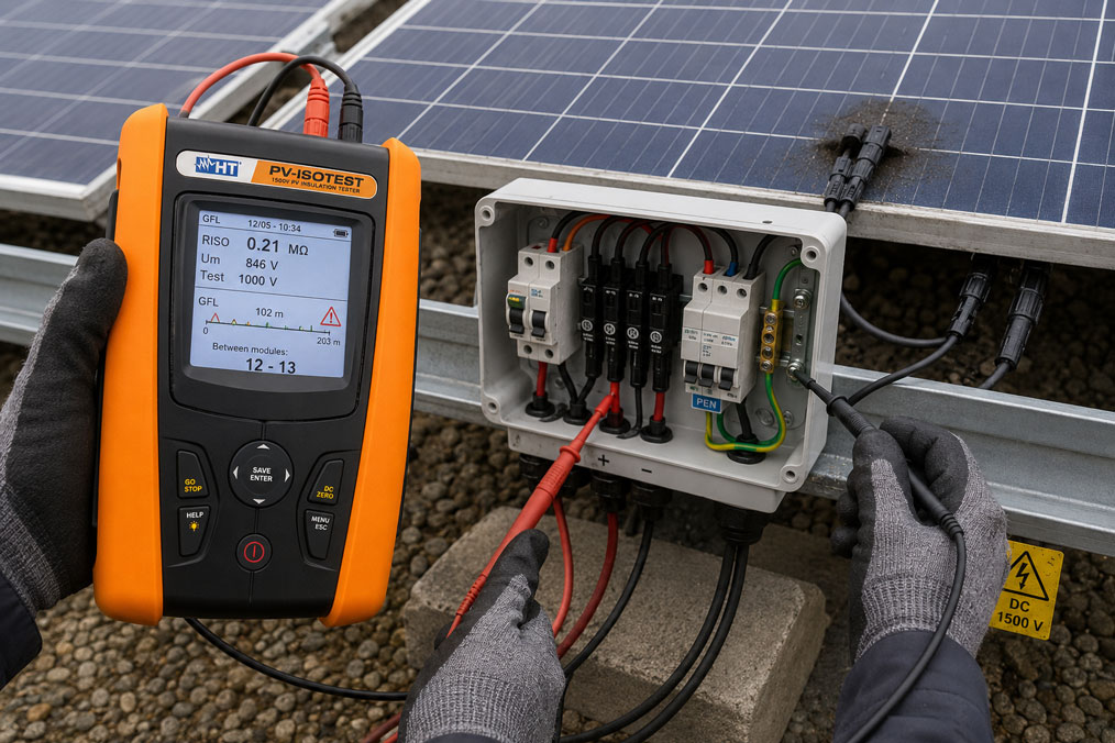
The inverter reports an excessively low insulation resistance, fails to start or repeatedly shuts down after rain. However, it often does not identify the actual fault location. In a system with multiple strings, hundreds of connectors and many metres of DC cable, this is where the actual troubleshooting process begins.
Typical causes include damaged solar cables, crushed wires, damp connectors, leaking junction boxes, cables contacting module frames or mounting structures, and defective surge protection devices. Particularly difficult are faults that occur only during rain, dew, high humidity, thermal expansion or a specific mechanical load.
A systematic troubleshooting procedure therefore does not begin by replacing the inverter. First, the system condition, polarity and string voltages are checked. The strings are then separated from one another and the affected circuit is narrowed down. Only after this is a targeted insulation measurement performed, followed by identification of the defective module, connector or cable section.
Suitable test instruments can be found in the ICS category Photovoltaic Instruments and PV Testers. Additional instruments for insulation measurements are grouped under Insulation Testers.
Table of Contents
- Why is troubleshooting PV strings particularly critical?
- What does an insulation fault in a PV system mean?
- Which fault locations occur particularly frequently?
- Why do insulation faults frequently occur after rain?
- What does the inverter insulation fault message mean?
- Check polarity and string voltage first
- Using voltages to earth to narrow down the fault
- Systematically separating the strings
- Correctly measuring insulation resistance
- Correctly selecting the test voltage
- Accounting for surge protection and electronics
- Locating the fault within a string
- Checking connectors and junction boxes
- Detecting damaged solar cables
- Inspecting modules and module frames
- Specifically reproducing intermittent faults
- Systematic diagnostic procedure
- Practical example: Insulation fault only after rain
- Typical errors during PV insulation testing
- What should be included in the documentation?
- Which products and solutions are suitable?
- Conclusion
- Frequently asked questions
Why is troubleshooting PV strings particularly critical?
PV modules generate voltage as soon as sufficient light reaches the cells. Switching off the inverter or opening the AC circuit breaker therefore does not automatically make the PV generator voltage-free.
With larger strings, several hundred to more than 1,000 V DC may remain present between the string conductors even after the inverter has been switched off.
An existing ground fault is particularly critical. In this case, normally non-current-carrying metal parts may assume a hazardous electrical potential.
Work and measurements on PV strings must therefore only be performed by appropriately qualified electrical specialists using suitable personal protective equipment and test equipment approved for the existing DC voltage.
Before troubleshooting begins, at least the following must be considered:
- system documentation and string layout,
- maximum open-circuit voltage of the strings,
- switching status of AC and DC disconnecting devices,
- manufacturer instructions for the inverter,
- possible energy storage systems and optimisers,
- installed surge protection devices,
- permissible measurement category and voltage rating of the test instruments,
- environmental conditions such as moisture and rain.
PV connectors must not be disconnected under load. Before opening string connections, it must be ensured that no current is flowing and that the specified disconnection sequence has been followed.
What does an insulation fault in a PV system mean?
Under normal conditions, the active DC conductors of the PV generator are sufficiently insulated from earth, module frames and the metallic mounting structure.
In simplified terms, the insulation resistance describes the resistance between the electrical PV circuit and earth:
RISO = U / ILeak
The poorer the insulation, the greater the unwanted leakage current to earth may become.
An insulation fault can occur between:
- DC positive and PE or earth,
- DC negative and PE or earth,
- a cell or conductor section and the module frame,
- a damaged cable and the metallic mounting structure,
- a connector and an earthed mounting structure.
A complete metallic ground fault is only an extreme case. Frequently, there is initially only a significantly reduced insulation resistance, for example due to moisture or damaged insulation.
This resistance can change considerably depending on weather, temperature and mechanical loading.
Which fault locations occur particularly frequently?
| Fault location | Typical cause | Typical behaviour |
|---|---|---|
| PV connectors | Not fully connected, incompatible connector combination, damaged seal, incorrect assembly | Fault particularly during moisture or rain |
| Solar cable | Crushing, abrasion, rodent damage, sharp sheet-metal edge | Permanent or movement-dependent ground fault |
| Module junction box | Leakage, damaged potting compound or cable entry | Insulation resistance decreases when wet |
| PV module | Damaged backsheet material, moisture ingress, mechanical damage | Partly temperature- or moisture-dependent |
| Module frame | Internal fault between electrical section and frame | Measurable resistance or ground fault to equipotential bonding |
| String combiner box | Moisture, contamination, damaged terminals or cables | Several strings may appear to be affected |
| DC surge protection | Defective or aged surge arrester | Low insulation resistance to PE possible |
| DC cable to inverter | Mechanical damage or water ingress | Fault remains even when the module string is disconnected |
Troubleshooting should therefore not begin at the modules if it has not yet been determined which string or cable section is affected.
Why do insulation faults frequently occur after rain?
Moisture can make existing weak points electrically conductive. A dry connector or damaged cable insulation may still have a high resistance during the day and become significantly lower in resistance after rain.
Typical moisture-dependent fault locations include:
- connectors that are not fully locked,
- damaged connector seals,
- connectors permanently lying in water,
- damaged cable sheaths,
- leaking module junction boxes,
- water inside string combiner boxes,
- condensation inside enclosures,
- contaminated surfaces with a conductive moisture film.
The time at which the fault occurs is therefore an important diagnostic indicator.
If the inverter reports the insulation fault predominantly:
- early in the morning,
- after rain,
- during fog,
- at high humidity
and the fault disappears again later, the system should be specifically checked for a moisture-dependent insulation weakness.
A test performed only on a dry afternoon may miss such a fault.
What does the inverter insulation fault message mean?
Many inverters check the insulation condition of the PV generator relative to earth before connecting to the grid. If the value falls below the limit defined by the manufacturer, the inverter does not start or disconnects the generator from grid operation.
The fault message initially means only:
The insulation condition of the connected DC system determined by the inverter is outside the permissible range.
It does not prove that the inverter itself is defective.
Depending on the system configuration, the measured insulation condition may be influenced by:
- several strings connected in parallel,
- DC combiner boxes,
- surge arresters,
- DC cables,
- modules,
- optimisers or other electronics.
With several strings connected in parallel, the resulting total insulation resistance is lower than the resistance of an individual string. The assessment of an entire PV array is therefore not identical to the assessment of an individual string.
Check polarity and string voltage first
Before an insulation measurement is performed, the basic electrical values of the affected string should be checked.
This includes, in particular, the voltage between positive and negative:
UPN = UPlus − UMinus
The measured open-circuit voltage is compared with the expected value of the string.
The following must be considered:
- number of modules connected in series,
- open-circuit voltage of the modules,
- module temperature,
- irradiance,
- possible optimisers or special module technology.
In addition, the polarity must be checked unambiguously. Reversed string polarity can cause considerable damage when connected to a combiner box or inverter.
Incorrect polarity is not automatically an insulation fault, but it may occur together with other fault conditions following modifications, repairs or incorrectly assembled cables.
The string identification should therefore always be compared with the actual measurement result.
Using voltages to earth to narrow down the fault
With a sufficiently pronounced ground fault, a voltage measurement relative to PE or the earthed mounting structure can already provide an important indication.
The following are measured:
- positive to PE,
- negative to PE,
- positive to negative.
With a stable ground fault, the two voltages to earth may approximately add up to the total string voltage.
Example:
- string voltage positive to negative approximately 600 V,
- positive to PE approximately 200 V,
- negative to PE approximately 400 V.
The ratio between these voltages may provide an indication of where the connection to earth is located within the string.
However, this method is not suitable for every type of fault. With high-resistance, moisture-dependent or intermittent insulation faults, the voltage values may be unstable or ambiguous.
In this case, a targeted insulation-resistance measurement is required.
Systematically separating the strings
In a system with several strings connected in parallel, it should first be determined which string is responsible for the low insulation resistance.
Troubleshooting is performed using a process of elimination:
- Document the system condition and fault message.
- Clearly identify the affected inverter or DC input.
- Electrically separate the strings from one another according to the specified switching sequence.
- Clearly label each string.
- Check the open-circuit voltage and polarity of each string.
- Compare the insulation condition of the strings individually.
- Investigate the abnormal string separately.
The advantage of this method is that it is not necessary to inspect every module on the roof immediately.
Example:
| String | Open-circuit voltage | Insulation resistance | Assessment |
|---|---|---|---|
| String 1 | 612 V | > 200 MΩ | Normal |
| String 2 | 609 V | > 200 MΩ | Normal |
| String 3 | 611 V | 0.7 MΩ | Abnormal |
| String 4 | 610 V | > 200 MΩ | Normal |
The further search can then be concentrated on String 3.
Correctly measuring insulation resistance
During a conventional insulation test, a defined DC test voltage is applied between the active PV circuit and earth. The test instrument determines the insulation resistance from the resulting test current.
With PV systems, it is particularly important to remember that the generator itself produces a DC voltage when exposed to light.
A conventional insulation tester must therefore not be connected to an active string without a measurement method specifically intended for PV systems.
With conventional test methods, the positive and negative conductors of the PV circuit disconnected from the inverter are connected together using a suitable device and then tested jointly against earth.
Depending on the system and test instrument, the following in particular must be considered before testing:
- the inverter must be disconnected,
- sensitive electronics must be taken into account,
- surge protection devices must be treated according to the manufacturer’s instructions,
- earthing of an active pole may need to be disconnected,
- the measuring range and test voltage must be set correctly.
Specialised PV insulation testers use measurement methods that are expressly designed for existing string voltages. In these cases, the connection and safety instructions for the respective instrument apply.
Correctly selecting the test voltage
The highest voltage available from the test instrument is not automatically the correct test voltage.
The selection depends on:
- the system voltage of the PV installation,
- the maximum permissible system voltage of the modules,
- the permissible test voltage of connected components,
- the applicable standard and test procedure,
- manufacturer instructions for the inverter and auxiliary devices.
Modern PV testers typically provide test voltages such as:
- 250 V DC,
- 500 V DC,
- 1,000 V DC,
- 1,500 V DC.
The test voltage must not simply be set to the maximum value, as electronics, surge arresters or other components that are not sufficiently voltage-resistant could otherwise be stressed or damaged.
Before every test, the data sheets of the components involved and the instructions for the PV tester being used must therefore be considered.
Accounting for surge protection and electronics
DC surge protection devices deliberately contain a voltage-dependent connection to PE. They can therefore influence the measurement result during an insulation test.
Depending on the type and test voltage, a connected surge arrester may:
- cause an apparently excessively low insulation resistance,
- become conductive during the test,
- be stressed by an unsuitable test voltage.
Before the insulation measurement, it must therefore be checked how the respective SPD manufacturer specifies that the test should be performed. Depending on the design and test procedure, removable protection modules are temporarily disconnected.
The following components must also be considered:
- inverters,
- power optimisers,
- string monitoring modules,
- transmitters,
- communication devices,
- active DC protection devices.
An insulation tester must not simply be connected blindly to a fully connected PV circuit.
Locating the fault within a string
Once the faulty string has been identified, the position within the series connection must be narrowed down.
Several methods are available for this purpose.
Voltage ratio to earth
With a stable ground fault, the ratio between positive-to-earth and negative-to-earth voltages may provide an approximate indication of the fault location.
If the fault is approximately in the middle of the string, for example, the voltages of both poles to earth may be similar.
If the fault is close to one end of the series connection, the two voltages differ more significantly.
Dividing the string
If the string can be safely separated in accordance with the manufacturer’s instructions, it can be investigated section by section.
An effective method is to divide it in half:
- divide the string into two sections,
- determine the affected section,
- divide that section again,
- repeat the procedure until the specific module or cable group is identified.
This means that not every module in a long string has to be tested individually.
Automatic ground fault localisation
Specialised PV test instruments can automatically evaluate the voltage ratios and use them to determine the probable area of a ground fault.
This can significantly reduce the time required, especially on large rooftop and ground-mounted PV systems.
Checking connectors and junction boxes
PV connectors are among the most mechanically stressed points in the DC wiring.
The following should be checked:
- complete locking,
- correct combination of compatible connector parts,
- condition of the seals,
- correctly tightened cable gland,
- tensile load on the cable,
- corrosion,
- discolouration and thermal damage,
- water or moisture inside the connector.
Connectors should not lie permanently on roof surfaces or in drainage channels. Cable routing must prevent water from running directly along the cable to the connector or junction box.
Even a connector that remains electrically conductive can cause an insulation fault if moisture creates a conductive connection to the earthed mounting structure.
Detecting damaged solar cables
Solar cables on rooftops are permanently exposed to UV radiation, wind, temperature changes and mechanical movement.
Typical damage is caused by:
- sharp profile edges,
- cable ties that are too tight,
- cables lying directly on the roof,
- crushing points beneath modules,
- sagging cable loops,
- rodent damage,
- incorrect fastening,
- installation work performed after the original installation.
Locations where a DC cable has been rubbing against an earthed metal edge for an extended period are particularly suspicious.
Initially, a fault may affect only the outer insulation. Moisture and continued movement can later create a conductive connection to the module frame or mounting system.
During visual inspection, attention should therefore not only be paid to completely severed cables. Pressure marks, discolouration, cuts and unusually tight bending radii are also relevant.
Inspecting modules and module frames
If the cables and connectors appear normal, the PV module itself must be examined.
Possible fault locations include:
- damaged backsheet,
- cracked or damaged module junction box,
- moisture ingress,
- damaged cable entry,
- mechanical damage following installation work,
- insulation faults between cells or internal wiring and the module frame.
Glass-glass modules and other module technologies have different designs and possible fault locations. The manufacturer’s requirements for insulation testing must therefore be observed.
The equipotential bonding of the mounting structure should also be checked. A poor connection to the module frame is not automatically the cause of the insulation fault, but it can alter the electrical conditions during a fault.
Specifically reproducing intermittent faults
Faults that are not present during maintenance are particularly difficult to diagnose.
Typical dependencies include:
- rain,
- morning dew,
- condensation,
- high module temperature,
- thermal expansion of connectors,
- wind-induced cable movement,
- specific tracker positions.
The inverter fault history should therefore be evaluated together with weather and operating conditions.
A table can be helpful:
| Time | Weather | Insulation fault | Observation |
|---|---|---|---|
| 06:40 | Heavy morning dew | Yes | Inverter does not start |
| 09:30 | Sunny, modules drying | No | Normal operation |
| 14:00 | Dry | No | Insulation measurement normal |
| Next morning | Dew | Yes | Fault occurs again |
This pattern strongly indicates a moisture-dependent fault rather than a random inverter defect.
Testing under wet conditions also considerably increases the electrical risk. Such tests may only be performed if the test procedure and working conditions allow them to be carried out safely.
Systematic diagnostic procedure
- Document the fault message: Record the inverter, MPPT input, time and insulation value.
- Check weather conditions: Determine whether there is a connection with rain, dew or temperature.
- Use the string plan: Identify the affected cable routes and module groups.
- Safely isolate the system: Follow the inverter and system requirements and secure against reconnection.
- Consider the DC current: Do not open connectors or fuse holders under load.
- Measure the open-circuit voltage: Compare the string voltage with the expected value.
- Check the polarity: Clearly verify positive and negative.
- Check voltage to earth: Compare positive to PE and negative to PE.
- Investigate the strings individually: Identify the abnormal string by comparing insulation values.
- Check the test setup: Account for the inverter, SPD and other electronics according to the manufacturer’s instructions.
- Measure the insulation resistance: Use a suitable PV test method and the correct test voltage.
- Narrow down the string: Use voltage ratios, sectional testing or a ground fault locator.
- Visually inspect the suspicious area: Check cables, connectors, junction boxes and module backsheets.
- Eliminate the fault: Correctly replace damaged components.
- Repeat the insulation measurement: Confirm the repair before reconnecting.
- Check the polarity again: Verify every string before connection.
- Return the system to operation: Follow the specified start-up sequence.
- Perform the final check: Check the inverter fault memory and insulation monitoring.
Practical example: Insulation fault only after rain
A rooftop PV system with four strings connected to one inverter reports an insulation fault on several rainy mornings. Around midday, the system regularly starts operating again.
Each string consists of 18 identical modules.
With the system dry, the following values are measured:
| String | UOC | RISO |
|---|---|---|
| 1 | 735 V | > 200 MΩ |
| 2 | 733 V | 85 MΩ |
| 3 | 736 V | > 200 MΩ |
| 4 | 734 V | > 200 MΩ |
String 2 still has a relatively high resistance, but already differs noticeably from the other three strings.
The following morning, the fault is investigated again under the specified safe test conditions. The insulation resistance of String 2 has now fallen to 0.8 MΩ, while the other strings continue to show high values.
Using fault localisation, the affected area is narrowed down to between modules 11 and 12.
The visual inspection reveals a connector that:
- was not fully locked,
- was lying directly on the roof surface,
- shows water around the cable seal.
The connector is correctly replaced using the specified components and then properly secured.
The repeat measurement gives:
RISO > 200 MΩ
The inverter fault message no longer occurs during several subsequent rain events.
The example demonstrates why a single dry measurement cannot reliably rule out an intermittent insulation fault.
Typical errors during PV insulation testing
| Error | Possible consequence | Suitable corrective action |
|---|---|---|
| Inverter switched off and string considered voltage-free | Hazardous DC voltage is underestimated | Always treat the PV generator as a voltage-generating source |
| Connector disconnected under load | Hazardous DC arc | Establish a safe current-free condition before disconnection |
| Strings not clearly labelled | Mix-up during reconnection | Clearly label all strings before disconnecting them |
| Polarity not checked again | Incorrect connection to inverter or combiner box | Measure every string before reconnecting it |
| Only the entire system measured | Faulty string remains unidentified | Systematically compare the strings individually |
| Testing performed only in dry weather | Moisture-dependent fault is overlooked | Consider the fault history and environmental conditions |
| Test voltage always set to maximum | Electronic components or SPD may be stressed | Observe the standard, system voltage and manufacturer approvals |
| Surge protection not considered | Incorrect insulation value or stress on the SPD | Observe the SPD manufacturer’s test requirements |
| Conventional insulation tester used on an active string without verification | Hazardous or invalid test setup | Use a suitable PV test method or PV test instrument |
| Only the cables are visually inspected | Defective junction box or module fault is overlooked | Inspect the entire affected string section |
| Fault only acknowledged by restarting the inverter | Cause remains present | Determine and eliminate the cause of the insulation fault |
| Repair performed without final measurement | Residual fault remains undetected | Recheck insulation resistance and polarity after the repair |
What should be included in the documentation?
Traceable troubleshooting documentation should include at least:
- system designation and location,
- inverter and affected MPPT input,
- string designation,
- number and type of modules,
- maximum system voltage,
- date and time,
- weather and moisture conditions,
- inverter fault code,
- insulation value reported by the inverter,
- open-circuit voltage of each string,
- measured polarity,
- voltage positive to PE,
- voltage negative to PE,
- insulation tester used,
- configured test voltage,
- insulation resistance of each string,
- condition of the surge arresters,
- suspected and actual fault location,
- photographs of cables and connectors,
- repair performed,
- insulation value after repair,
- final functional test of the inverter.
For intermittent faults, the weather conditions are particularly important. A measured value without information about whether the system was dry or wet is significantly less useful for subsequent root-cause analysis.
Which products and solutions are suitable?
PV-ISOTEST for insulation measurement and fault localisation
The PV-ISOTEST is specifically designed for electrical safety testing and troubleshooting of PV modules, strings and PV arrays.
The instrument supports insulation tests on systems with voltages up to 1,500 V DC and provides test voltages of 250 V, 500 V, 1,000 V and 1,500 V DC.
The GFL Ground Fault Locator function is particularly useful for troubleshooting. Once a faulty string has been identified, it can be used to determine the probable area of the insulation fault within the module series.
The PV-ISOTEST can also test the continuity of the protective conductor or equipotential bonding using a test current greater than 200 mA.
PVCHECKs-Pro installation tester up to 1,500 V DC
The PVCHECKs-Pro combines several tests for the commissioning and maintenance of photovoltaic systems.
Functions include:
- polarity testing,
- continuity testing of the equipotential bonding conductor,
- insulation resistance measurement,
- open-circuit voltage measurement up to 1,500 V DC,
- short-circuit current measurement up to 40 A DC.
The instrument is therefore particularly suitable when complete tests of strings and PV systems need to be documented in addition to targeted insulation-fault troubleshooting.
PV CHECK for PV systems up to 1,000 V DC
The PV CHECK is designed for safety and functional tests on PV systems up to 1,000 V DC.
The instrument provides, among other functions:
- insulation resistance measurement with 250, 500 and 1,000 V DC,
- open-circuit voltage measurement up to 1,000 V DC,
- short-circuit current measurement,
- automatic polarity indication,
- low-resistance measurement of the protective conductor.
General insulation testers
For suitable circuits that have been safely de-energised, conventional Insulation Testers are also available.
When used on PV systems, however, it must first be checked whether the test instrument, connection method, measurement category and maximum input voltage are suitable for the specific PV circuit.
A general insulation tester is not automatically a PV installation tester.
ICS Schneider Messtechnik provides support in selecting the PV test instrument, insulation test method, test voltage and suitable accessories, as well as in assembling measurement solutions for commissioning, maintenance and systematic troubleshooting of PV systems.
Conclusion
An insulation fault message from the inverter does not automatically mean that the inverter is defective. The cause is frequently located in the PV generator, DC wiring or connected protection components.
Troubleshooting should proceed from the general to the specific. First, the time of the fault, open-circuit voltage and polarity are checked. The individual strings are then compared.
Voltage measurements from positive and negative to earth can already provide indications of the affected area in the case of a stable ground fault. For high-resistance or intermittent faults, however, an insulation-resistance measurement is required.
The test voltage must be suitable for the system voltage and all components involved. During a conventional insulation test, the inverter, surge protection and other electronics must not remain in the test circuit without first checking whether this is permitted.
Faults occurring after rain or morning dew frequently indicate moisture inside connectors, junction boxes or damaged cables. Testing only under dry conditions may miss such faults.
Once the faulty string has been identified, the search can be continued using voltage ratios to earth, sectional isolation or a specialised ground fault locator until the suspicious module or cable section has been identified.
After every repair, the insulation resistance and polarity must be checked again before the string is reconnected to the inverter or string combiner box.
Frequently asked questions about insulation faults in PV strings
Why does the inverter report an insulation fault?
The measured insulation resistance of the connected PV generator to earth is below the range accepted by the inverter. Possible causes include modules, cables, connectors, combiner boxes or surge protection devices.
Is the PV string voltage-free when the inverter is switched off?
No. PV modules continue to generate DC voltage when exposed to light. Switching off the inverter does not disconnect the generator from its own energy source.
How can I determine which string is faulty?
The strings are separated from one another according to the safe system procedure and then individually tested for open-circuit voltage, polarity and insulation resistance.
Can I detect a ground fault by measuring the voltage to PE?
Frequently yes, in the case of a stable ground fault. The voltages from positive to PE and negative to PE may together approximately correspond to the total string voltage, and their ratio can provide an indication of the fault location.
Why does the fault occur only after rain?
Water can create an additional conductive path to earth at damaged cables, connectors or junction boxes. Once the system dries, the insulation resistance increases again.
Which test voltage should I use for a PV string?
The test voltage depends on the system voltage, applicable standard, modules and other connected components. It must not simply be set to the maximum value available from the test instrument.
Does the inverter have to be disconnected during an insulation test?
For conventional insulation test methods, generally yes, in accordance with the manufacturer’s instructions and the applicable test procedure. Specialised PV test instruments may use their own measurement methods for live PV strings. In these cases, the requirements of the respective test instrument are decisive.
Why must the surge protection be considered?
A DC surge arrester contains a voltage-dependent connection to PE and can therefore influence the measured value or be stressed by an unsuitable test voltage.
Can a damaged PV cable cause a fault only during windy conditions?
Yes. If a damaged cable rubs against an earthed metal edge, the electrical contact can change depending on movement and wind.
Can a module itself cause a ground fault?
Yes. Damaged backsheets, junction boxes, cable entries or internal insulation faults can create a conductive connection to the module frame or mounting structure.
Why is comparing several strings helpful?
Identical strings under similar conditions should have comparable electrical characteristics. A significantly lower insulation resistance in one individual string is therefore an important indication for further troubleshooting.
What is a Ground Fault Locator?
A Ground Fault Locator is a measuring function or specialised test method that helps identify the position of an insulation fault within the module series after the faulty string has been identified.