


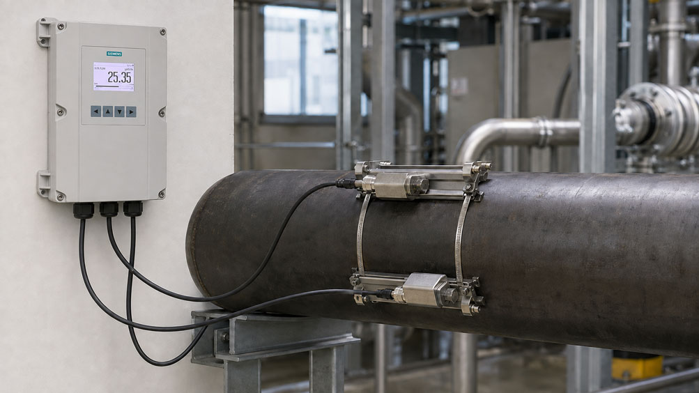
In clamp-on ultrasonic measurement, the sensors are attached to the outside of the pipe. The pipe does not need to be opened or cut, and the sensors do not come into contact with the medium. Nevertheless, the measurement is not automatically correct simply because two ultrasonic sensors have been mounted on the pipe.
The path taken by the ultrasonic signal between the two sensors is crucial. Depending on the pipe diameter, pipe material, wall thickness, medium and signal attenuation, a direct Z path, a reflected V path or a multiply reflected W path may be suitable. An unsuitable arrangement results in a weak signal, unstable transit-time measurement or systematic measurement deviations.
This article explains the differences between V, Z and W mounting, presents the most important selection criteria and describes how sensor spacing, pipe data and signal quality are checked in practice.
Table of Contents
- How clamp-on transit-time measurement works
- Distinguishing sound paths, traversals and measurement paths
- Direct comparison of V, Z and W paths
- When the V path is suitable
- When the Z path offers advantages
- When a W path can be useful
- Why pipe diameter alone is not enough
- Influence of the medium, gas bubbles and solids
- Considering pipe material, wall thickness and lining
- Determining and transferring the correct sensor spacing
- Selecting a suitable measuring point on the pipe
- Assessing signal quality correctly
- Practical examples for small and large pipes
- Recommended procedure for installation and commissioning
- Common installation and selection errors
- Suitable clamp-on systems from ICS Schneider
- Conclusion
- FAQ: V, Z and W mounting for clamp-on ultrasonic measurement
How Clamp-on Transit-Time Measurement Works
In transit-time difference measurement, two sensors alternately transmit ultrasonic signals through the pipe wall and the medium, both with and against the direction of flow. The signal takes slightly less time when travelling with the flow and slightly more time when travelling against it. From this transit-time difference, the transmitter calculates the average flow velocity and, using the pipe cross-sectional area, the volumetric flow rate.
In simplified terms:
Volumetric flow rate = average flow velocity × internal pipe cross-sectional area
The actual internal diameter is decisive for the internal cross-sectional area. The outside diameter, wall thickness and, where applicable, the thickness of any lining must therefore be entered correctly. Even an error in the internal diameter directly affects the calculated area and therefore the volumetric flow rate.
The transit-time difference is very small. The transmitter must therefore not only determine the arrival time of the received signal precisely, but also calculate the sound path through the sensor, pipe wall and medium correctly. The selected V, Z or W arrangement influences the length of the sound path, the number of reflections and the signal strength.
Distinguishing Sound Paths, Traversals and Measurement Paths
The terminology is not always used consistently in practice. The following distinction is helpful when selecting an arrangement:
- Sound path or mounting arrangement: Geometry of the ultrasonic signal between a pair of sensors, for example V, Z or W.
- Traversal: One passage of the signal through the medium from one side of the pipe to the other.
- Reflection: Redirection of the signal at the opposite pipe wall.
- Measurement path or channel: An independent pair of sensors that provides a separate measured value.
A W path has multiple traversals, but is not automatically a multipath measurement. A true two-path or four-path measurement uses several sensor pairs at different positions to capture the flow profile more effectively or to improve availability.
Manufacturers sometimes use different terms. A V path is often referred to as a reflection or Reflect mounting arrangement, while a Z path is referred to as a direct or Direct arrangement. The equipment and sensor manuals must be consulted to determine which configurations a particular measuring system actually supports.
Direct Comparison of V, Z and W Paths
| Mounting arrangement | Sensor position | Typical sound path | Typical suitability | Important disadvantage |
|---|---|---|---|---|
| V path | Both sensors on the same side of the pipe | Two traversals with one reflection | Small to medium-sized pipes, good signal conditions | More attenuation than with the direct Z path |
| Z path | Sensors on opposite sides of the pipe and axially offset | One direct traversal | Large pipes, highly attenuating pipes or media, weak signals | More demanding geometric alignment |
| W path | Both sensors on the same side of the pipe | Multiple traversals and reflections | Small pipes and clean media with good acoustic transmission | Higher attenuation; not supported by every system |
This classification is a guide, not a fixed diameter rule. The sensor design, frequency, pipe material, lining, medium and temperature may mean that different mounting arrangements are required for two pipes with the same nominal diameter.
When the V Path Is Suitable
With a V path, both sensors are located on the same side of the pipe. The signal traverses the medium, is reflected at the opposite pipe wall and returns to the second sensor. This creates a longer effective sound path than a direct traversal.
Advantages of the V path:
- both sensors are accessible from the same side of the pipe,
- installation and maintenance are often easier,
- the longer sound path increases the measurable transit-time difference,
- the sensors can be aligned precisely on a common mounting rail,
- the arrangement is the preferred initial configuration for many liquid applications.
The V path requires the signal to pass through the pipe wall and medium and survive the reflection with sufficient strength. With very large pipe diameters, highly attenuating media, thick linings or unfavourable pipe materials, the received signal may become too weak. In such cases, the shorter Z path often provides better signal reserves.
When the Z Path Offers Advantages
With a Z path, the sensors are mounted on opposite sides of the pipe. The signal traverses the medium only once and reaches the second sensor without being reflected at the opposite pipe wall. The sound path is therefore shorter and attenuation is generally lower.
The Z path is often useful for:
- large pipe diameters,
- weakly received signals in V mode,
- highly attenuating pipe materials or linings,
- media with increased acoustic attenuation,
- high temperatures or applications with limited coupling capability,
- plastic pipes when the sensor or manufacturer instructions require direct mounting.
The greater challenge is alignment. The sensors must be positioned correctly relative to one another both longitudinally and around the pipe circumference. A small deviation from the calculated position can place the receiver outside the strongest part of the sound field. On large pipes, the opposite position should therefore be transferred carefully using a circumference tape, template or suitable mounting rail.
When a W Path Can Be Useful
With a W path, the signal is reflected several times between the pipe walls before reaching the second sensor. This increases the effective path through the medium. On small pipe diameters, it can increase the transit-time difference and improve resolution.
A W path is particularly worth considering when:
- the pipe diameter is small,
- the medium is clean and has good acoustic transmission properties,
- the pipe wall and coupling cause only minor signal losses,
- the calculated sensor spacing can be implemented mechanically,
- the specific measuring system supports this mounting arrangement.
More traversals do not automatically produce a better measurement. Every additional distance and reflection weakens the signal. With air bubbles, solids, thick-walled pipes or attenuating linings, a W path may be unusable despite the longer transit-time difference. In that case, the V or Z path is preferable.
Why Pipe Diameter Alone Is Not Enough
The common rule of thumb “small pipe W, medium pipe V, large pipe Z” is only a starting point. Several parameters must be considered together for a reliable selection:
- actual outside pipe diameter,
- wall thickness and the resulting calculated internal diameter,
- pipe material and speed of sound in the material,
- thickness and material of any lining,
- speed of sound and attenuation in the medium,
- medium temperature and temperature range,
- sensor frequency and sensor size,
- available installation space,
- expected flow velocity,
- signal quality at the actual measuring point.
The transmitter or sizing software uses this information to calculate the sound angle and required sensor spacing. The calculated arrangement must then be checked for plausibility on the actual pipe. A theoretically possible sensor spacing may, for example, be impossible to install in practice because of a weld seam, support or pipe insulation.
Influence of the Medium, Gas Bubbles and Solids
Transit-time difference measurement works most reliably with a single-phase medium in which the ultrasonic signal can propagate clearly. Gas bubbles in liquids and solid particles can scatter, reflect or attenuate the signal.
Liquids
Clean liquids such as water, many oils or homogeneous process liquids are typical applications. The speed of sound used in the calculation must match the medium and temperature. An incorrect medium data set can result in incorrect sensor spacing or an implausible measured speed of sound.
Gas Bubbles and Pipes That Are Not Completely Full
Even small amounts of gas can impair signal quality if distributed unfavourably. On horizontal liquid pipes, the sensors should therefore not be mounted at the highest point of the pipe, where gas can accumulate. Clamp-on transit-time measurement also requires the pipe to be completely full.
Solids and Deposits
Suspended solids can attenuate the signal. Deposits on the inside of the pipe also alter the effective internal diameter and the acoustic structure. For heavily loaded or multiphase media, it must be determined whether the transit-time method is still suitable or whether a different measuring principle is required.
Considering Pipe Material, Wall Thickness and Lining
Before and after passing through the medium, the ultrasonic signal also travels through the pipe wall. The material, surface condition and geometry therefore have a significant influence on signal transmission.
The following are particularly important:
- Outside diameter: Do not simply adopt the nominal diameter; measure the actual value or determine it from reliable pipe data.
- Wall thickness: Corrosion, manufacturing tolerances or unknown pipe schedules may cause deviations from the design value. Check with a wall thickness gauge if necessary.
- Lining: The material, thickness and adhesion affect the sound path. A partially detached lining can severely impair the measurement.
- Coating: Loose paint, rust, scale and uneven surfaces prevent reliable acoustic coupling.
- Weld seams: Do not mount sensors directly on weld seams or pronounced uneven areas.
- Multilayer pipes: The measuring system must be capable of accounting for different sound velocities and interfaces.
A small, smooth and clean contact surface must be prepared before installation. Firmly adhering, uniform coatings may remain only if permitted by the sensor instructions and if sufficient signal quality can be demonstrated.
Determining and Transferring the Correct Sensor Spacing
The sensor spacing is not a freely selectable installation value. It is determined by the pipe data, medium, sensor design and mounting path. After V, Z or W has been selected, the transmitter calculates the required spacing.
The following points are crucial during practical implementation:
- Always measure the spacing between the sensor reference marks defined by the manufacturer.
- Do not relate the calculated value to housing edges or cable glands.
- Align both sensors exactly parallel or as specified in the installation instructions.
- For Z mounting, also transfer the correct position to the opposite side of the pipe.
- Recalculate the spacing after changing the pipe data, medium or mounting arrangement.
- Secure the sensors mechanically after fine adjustment.
An incorrectly transferred spacing changes the actual sound angle and may distort the calculated flow velocity. A strong received signal alone therefore does not prove that the spacing is geometrically correct.
Selecting a Suitable Measuring Point on the Pipe
Even a correctly selected sound path will not provide reliable results if the flow profile at the measuring point is severely disturbed. The sensors should be installed on a straight pipe section with a flow profile that is as symmetrical and fully developed as possible.
The following should be avoided or allowed for with sufficient distance:
- pumps,
- partially closed valves,
- control valves,
- pipe bends in several planes,
- tees and pipe junctions,
- reducers and expanders,
- heat exchangers and mixers,
- areas where two-phase flow may occur.
Universal specifications such as “ten pipe diameters upstream and five downstream of the measuring point” are not sufficient for every disturbance and every accuracy target. The required upstream and downstream straight runs must be determined from the manufacturer’s specifications, the arrangement of the fittings and the desired measurement uncertainty.
On a horizontal liquid pipe, lateral mounting positions are often more favourable than the top or bottom of the pipe. Gas bubbles can collect at the top and deposits at the bottom. On vertical pipes, upward flow is generally advantageous because it helps keep the pipe completely full.
Assessing Signal Quality Correctly
After installation, the assessment must not be based solely on a displayed flow value. Modern clamp-on transmitters provide diagnostic values whose names vary by manufacturer.
Typical criteria include:
- received signal or signal amplitude,
- signal-to-noise ratio,
- signal quality or correlation value,
- receiver gain value,
- measured speed of sound in the medium,
- stability of the transit time and transit-time difference,
- zero-point stability when the medium is actually stationary,
- stability of the flow value across several operating conditions.
A high gain value may indicate that the transmitter has to amplify a weak signal significantly. An implausible speed of sound often indicates incorrect pipe or medium data, unsuitable sensor spacing, poor coupling or an incorrect signal path.
Limit values for signal quality and gain are device-specific. They must not be transferred from one system to another. The diagnostic information for the transmitter being used is authoritative.
Practical Examples for Small and Large Pipes
Small Water Pipe
On a small, thin-walled metal pipe carrying clean water, the direct Z path can be very short. A V path or, if supported by the device, a W path extends the path through the medium and may make the transit-time difference easier to resolve. Good coupling and sufficiently strong reflections are essential.
Large Cooling-Water Pipe
On a large steel pipe, the V path becomes significantly longer and is therefore subject to greater attenuation. If the signal reserve is insufficient, Z mounting reduces the number of traversals and reflections. The opposite sensor position must be determined with geometric precision.
Lined Process Pipe
On a lined pipe, additional interfaces and uneven adhesion can impair the signal. A direct Z path can reduce attenuation. The lining material and thickness must first be recorded correctly and the actual signal quality checked.
Temporary Verification Measurement
For a portable comparison measurement, the geometry of a previous measuring point should not be adopted automatically. The pipe data and sensor spacing must be checked again for every measuring point. Brief documentation of the pipe circumference, wall thickness, mounting path, sensor spacing and diagnostic values considerably improves reproducibility.
Recommended Procedure for Installation and Commissioning
- Define the measuring task: Specify the medium, temperature, pressure, flow range and required accuracy.
- Record the pipe data: Determine the outside diameter, wall thickness, material and lining.
- Select the measuring point: Check the filling condition, upstream straight run, fittings and accessibility.
- Select the sensors: Determine the size, frequency, temperature version and mounting system.
- Calculate the mounting arrangement: Check the V, Z, W, Reflect or Direct path proposed by the transmitter.
- Transfer the sensor spacing: Relate the calculated spacing to the correct reference marks.
- Prepare the pipe surface: Remove loose coatings, rust and uneven areas from the sensor area.
- Apply coupling compound: Establish air-free acoustic coupling between the sensor and pipe.
- Align the sensors: Maintain the precise longitudinal and circumferential positions.
- Fasten the sensors: Ensure uniform contact pressure without damaging the sensor or pipe.
- Check the diagnostic values: Assess signal strength, quality, gain and speed of sound.
- Perform fine adjustment: Optimise only within the manufacturer’s specifications and document the final spacing.
- Check the zero point: Adjust only when flow has safely stopped and the pipe is completely full.
- Check the plausibility of the measured value: Use operating data, the pump curve or a comparison measurement.
- Document the installation: Record the pipe data, path, sensor positions, spacing and diagnostic values.
Common Installation and Selection Errors
| Error | Typical consequence | Better approach |
|---|---|---|
| Selecting the mounting arrangement based only on the nominal diameter | Signal path does not match the pipe and medium | Include all pipe, medium and sensor data |
| Confusing DN with the actual outside diameter | Incorrect internal diameter and sensor spacing | Measure the outside diameter or use reliable pipe data |
| Ignoring the wall thickness or lining | Incorrect sound angle and volumetric flow rate | Record the actual wall and lining data |
| Assuming that the W path is always more sensitive | Signal is lost because of additional attenuation | Check the signal reserve and supported modes |
| Failing to align Z sensors exactly opposite one another | Weak or unstable received signal | Transfer the circumferential position using a tape or template |
| Measuring the sensor spacing at the housing edges | Actual sound path deviates from the calculation | Use the manufacturer’s reference marks |
| Too little or uneven coupling compound | Air pockets and severely attenuated signal | Ensure clean, continuous coupling |
| Mounting sensors at the highest point of a liquid pipe | Gas bubbles interfere with the sound path | Select a suitable lateral pipe position |
| Considering only the flow value | Unstable or incorrect measurement remains undetected | Document diagnostic values and the speed of sound |
| Setting the zero point without ensuring that flow has stopped | Systematic offset across the entire measuring range | Adjust the zero point only when zero flow has been verified |
Suitable Clamp-on Systems from ICS Schneider
SITRANS FS220 – Stationary Clamp-on Measurement for Liquids
The SITRANS FS220 clamp-on ultrasonic flowmeter consists of the SITRANS FST020 transmitter and externally mounted FSS200 ultrasonic sensors. It is suitable for continuously monitoring liquid processes without opening the pipe.
The shop product page specifies an accuracy of 1% of the flow rate and repeatability of 0.25% in accordance with ISO 11631. The pipe and medium data are stored in the transmitter for installation; the sensor arrangement and calculated spacing must then be implemented in accordance with the FSS200 installation instructions.
SITRANS FS230 – Demanding and Multipath Applications
The SITRANS FS230 combines the FST030 transmitter with FSS200 clamp-on sensors. The system is designed for demanding applications, hazardous areas and, depending on the version, measurements with up to four paths.
Multiple true measurement paths must not be confused with a multiply reflected W sound path. Multipath systems use additional sensor pairs to capture different areas of the flow profile or provide redundancy.
SITRANS FS290 – Portable Verification and Comparison Measurements
The SITRANS FS290 ultrasonic flow measurement system includes the battery-powered FST090 transmitter and FSS220 clamp-on sensors. It is suitable for temporary flow checks, energy analyses, pump tests and troubleshooting on existing systems.
Further devices can be found in the flow measurement technology category at ICS Schneider.
Conclusion
The choice between a V, Z and W path determines the length of the sound path, the number of reflections and the available signal reserve. The pipe diameter is important, but is not sufficient on its own for making the selection.
V Path as an Easily Accessible Reflection Arrangement
The V path is a suitable initial configuration for many small to medium-sized pipes. Both sensors are located on the same side of the pipe, and the longer sound path improves the resolvable transit-time difference.
Z Path for Lower Attenuation
On large pipes or where the signal is weak, direct mounting shortens the sound path. However, the sensors must be aligned particularly precisely on opposite sides of the pipe.
W Path Only with Sufficient Signal Reserve
Multiple reflections can improve measurement resolution on small pipes, but they weaken the signal. The W path is only useful if the medium, pipe and measuring system support this arrangement.
Practical Rule
Define the measuring task → record the actual pipe data → check the medium and temperature → select suitable sensors → calculate a supported V, Z, W, Reflect or Direct path → transfer the sensor spacing to the correct reference marks → prepare the pipe surface → couple and align the sensors correctly → check signal quality, gain and speed of sound → verify the plausibility of the measured value → document the final installation and diagnostic values.
FAQ: V, Z and W Mounting for Clamp-on Ultrasonic Measurement
What is the difference between V and Z mounting?
With a V path, both sensors are located on the same side of the pipe and the signal is reflected at the opposite pipe wall. With a Z path, the sensors are located on opposite sides; the signal traverses the medium directly and without an additional reflection.
Which mounting arrangement is suitable for large pipes?
The Z path is frequently used for large pipe diameters because the direct traversal causes less attenuation. However, the sensor design, pipe, medium and actual signal quality remain decisive.
When is the W path used?
A W path can extend the effective sound path on small pipes under very good acoustic conditions. However, it causes additional attenuation and is not supported by every measuring system.
Is Reflect the same as V mounting?
In many equipment manuals, Reflect corresponds to a reflected arrangement such as the V path. Direct usually refers to direct Z mounting. The precise manufacturer-specific definition must be checked in the sensor manual.
Can the mounting arrangement be selected based only on the pipe diameter?
No. Wall thickness, pipe material, lining, medium, temperature, sensor frequency and signal attenuation also influence the selection.
Why must the sensor spacing be maintained precisely?
Together with the pipe and medium data, the spacing determines the actual sound angle. Incorrect spacing can impair signal quality and cause a systematic measurement error.
Between which points is the sensor spacing measured?
The spacing is measured between the sensor reference marks specified by the manufacturer. The housing edge, cable outlet or tensioning strap are not valid reference points unless stated otherwise by the manufacturer.
Why can the measured value be incorrect despite a strong signal?
A strong signal merely confirms that acoustic energy is being received. Incorrect pipe data, unsuitable spacing, a disturbed flow profile or an incorrectly set zero point can nevertheless cause systematic deviations.
Where should sensors be mounted on a horizontal liquid pipe?
Lateral positions are often favourable. The highest point may contain gas bubbles, while deposits may accumulate at the lowest point. The exact position depends on the mounting arrangement and manufacturer’s instructions.
Does the pipe have to be completely full?
Yes. Transit-time measurement for liquids requires an uninterrupted sound path through the medium. Partial filling or large gas accumulations can make the measurement impossible or unstable.
Can a clamp-on device measure through pipe insulation?
As a rule, the insulation is opened in the sensor area so that the sensors are placed directly on and acoustically coupled to the pipe wall. After installation, the insulation must be restored correctly without placing stress on the sensors or cables.
How can I identify an unsuitable mounting arrangement?
Indications include a weak or unstable received signal, high required gain, an implausible speed of sound, fluctuating transit-time values or a non-reproducible flow value. The data, coupling and spacing must then be checked, and a different path considered if necessary.
Is a W path a multipath measurement?
No. A W path uses one pair of sensors with multiple traversals. A true multipath measurement uses several independent sensor pairs or measurement channels.
When is a portable clamp-on measurement useful?
It is suitable for verification measurements, energy audits, pump tests, locating faulty stationary measuring points and assessing potential installation locations before permanent installation.