


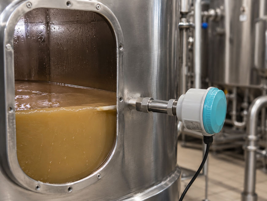
Capacitive point level switches can detect liquids, pastes, slurries, powders and bulk solids. Unlike a float switch, they do not respond to mechanical movement, but to changes in an electric field in the area of the probe.
How strongly this field changes when the probe is covered depends significantly on the medium and its relative dielectric constant εr. Water, for example, causes a much stronger capacitive change than air, oil or a dry bulk solid with a low dielectric constant.
For reliable point level detection, it is therefore not sufficient simply to screw the sensor into the vessel. Sensitivity or switching point must be matched to the actual installation conditions.
The actual capacitive signal is influenced by factors including:
- medium,
- dielectric constant,
- vessel wall,
- distance from metallic internals,
- buildup,
- moisture,
- foam,
- installation position
.
A capacitive point level switch should therefore ideally be taught or adjusted only after final installation in the actual process. The decisive factor is not a theoretical εr value alone, but the difference between the reliably detectable states “probe uncovered” and “probe covered” under real operating conditions.
Suitable instruments can be found under level measurement technology at ICS Schneider or under point level detection.
Table of Contents
- How does a capacitive point level switch work?
- Why is the dielectric constant important?
- How large must the difference between uncovered and covered be?
- What does teach-in mean for a point level switch?
- How to perform an empty adjustment correctly
- When is a full adjustment useful?
- What influence does the vessel wall have?
- Capacitive sensor on a plastic vessel
- Consider metallic internals and piping
- Why is buildup problematic?
- Adjusting the point level switch with existing buildup
- Moisture and changing product composition
- How does foam affect point level detection?
- Why is hysteresis necessary?
- Do not set sensitivity unnecessarily high
- Selecting the correct installation position
- Distinguishing minimum and maximum point level
- Setting fail-safe switching behavior correctly
- What happens when the product changes?
- Practical example: liquid with buildup
- Typical fault patterns
- Recommended commissioning procedure
- Suitable capacitive point level switches from ICS Schneider
- Conclusion
- FAQ
How does a capacitive point level switch work?
The basic principle can be simplified as an electrical capacitor.
The probe forms one electrode. The surroundings, or in many applications the metallic vessel wall, form the counter or reference electrode.
The capacitance depends, among other factors, on:
- electrode geometry,
- distance,
- surface area,
- material between the electrodes.
In simplified form, capacitance can be represented as:
C ∝ εr
If the medium in the electric field of the probe changes, the measured capacitance changes as well.
Probe uncovered
The surroundings of the probe consist mainly, for example, of:
air
.
Probe covered
The electric field is partially or completely influenced by the process medium.
The electronics detect this change and switch the output.
Why is the dielectric constant important?
The relative dielectric constant describes, in simplified terms, how strongly a material influences the electric field compared with a vacuum or air.
Air
has approximately:
εr ≈ 1
.
Water
on the other hand has a very high relative εr value at room temperature in the order of:
εr ≈ 80
.
Many oils, plastics, powders and organic products have significantly lower values.
For practical applications, this means
The greater the difference between:
probe uncovered
and:
probe covered
the easier it is for the sensor to establish a stable switching point.
A product with a low dielectric constant, on the other hand, often requires a more sensitive setting or a sensor suitable for this application.
How large must the difference between uncovered and covered be?
The absolute εr value of the medium alone is not decisive.
What matters is the actual signal change at the installed sensor.
This also depends on:
- probe shape,
- probe length,
- vessel geometry,
- process connection,
- distance from the vessel wall,
- product coverage,
- buildup.
The same sensor with the same medium may therefore require different settings in two different installation situations.
What does teach-in mean for a point level switch?
Teach-in generally means that the sensor stores one or more actual process states as reference values.
Depending on the instrument, this may be carried out using, for example:
- pushbuttons,
- local display,
- potentiometer,
- software or communication.
With simpler capacitive point level switches, an automatic teach-in is not necessarily performed. Instead, sensitivity or switching point is manually adjusted to the process.
Typical reference states are
probe uncovered
and, where applicable:
probe fully covered
.
How to perform an empty adjustment correctly
For many applications, the condition with the probe uncovered is the most important reference.
The vessel does not necessarily have to be completely empty
The decisive factor is that the area around the probe corresponds to the actual condition that later needs to be reliably detected as:
uncovered
.
Ideally, the adjustment should already be performed
- in the final vessel,
- in the final installation position,
- with connected piping,
- with existing metallic internals,
- under process conditions that are as realistic as possible.
This ensures that the static capacitive influences of the surroundings are already part of the basic setting.
When is a full adjustment useful?
If the sensor can detect or store both the uncovered and covered states, adjustment using the actual medium provides additional reliability.
The sensor then knows both states
for example:
Cuncovered
and:
Ccovered
.
The switching point can then be positioned with a suitable safety margin between the two states.
Adjustment with the actual product is particularly useful for:
- products with low εr,
- heavy buildup,
- changing process conditions,
- critical switching functions.
What influence does the vessel wall have?
In conventional capacitive measurement arrangements, the surroundings of the probe are part of the electric measuring field.
A metallic vessel wall can act as a defined reference surface.
This is why the distance from the wall affects the basic capacitance
If a probe is installed directly next to a metallic vessel wall, for example, the electric field may develop differently than when the probe is installed farther inside the vessel.
A subsequent change in:
- probe position,
- process connection,
- vessel geometry
may therefore require readjustment.
Capacitive sensor on a plastic vessel
With a non-conductive vessel, depending on the sensor principle, the metallic vessel wall is not available as a conventional reference electrode.
Whether and how the point level can nevertheless be detected reliably therefore depends strongly on the specific sensor design.
Some capacitive sensors
can, for example:
- operate independently of a metallic vessel wall,
- detect through a non-metallic wall,
- operate using a separate reference geometry.
For plastic vessels, the manufacturer specifications of the specific sensor must therefore always be taken into account.
Consider metallic internals and piping
It is not only the vessel wall that influences the capacitive field.
Nearby:
- agitators,
- heating coils,
- pipes,
- braces,
- internals
can also change the basic capacitance.
Particularly critical
are changes made after commissioning.
If, for example, a metallic pipe is later installed directly next to the probe, the measured value may shift even though the level remains unchanged.
Capacitive point level sensors should therefore ideally be adjusted in their final mechanical environment.
Why is buildup problematic?
After the level drops, many media leave a thin layer of product on the probe.
This layer continues to influence the capacitance.
The sensor therefore no longer sees exactly the same condition as with a completely clean probe
The result may be:
probe actually uncovered → sensor still indicates covered
.
Particularly critical are:
- sticky liquids,
- pastes,
- moist powders,
- conductive deposits,
- hygroscopic products.
Adjusting the point level switch with existing buildup
A perfectly clean sensor is not always the best reference condition for adjustment.
In a process with unavoidable product buildup
it is useful to take into account the realistic condition after the product has drained away.
A practical procedure can be, for example:
- Cover the probe with product.
- Lower the product level again.
- Leave the typical buildup on the probe.
- Adjust this condition so that it is reliably recognized as “uncovered”.
- Then check full coverage again.
This provides a better margin between:
buildup
and:
actual coverage
.
Point level switches with special buildup compensation technologies can make this application even easier.
Moisture and changing product composition
Especially with bulk solids, moisture can significantly change the capacitive behavior.
Example
A dry powder has a comparatively low effective dielectric constant.
If the same material absorbs moisture, the capacitive signal can increase significantly.
The selected switching point must therefore provide sufficient margin for the entire actual product range.
With changing products
at minimum, the following should be checked:
- product with the lowest expected εr,
- product with the highest expected εr,
- driest condition,
- wettest condition.
The parameterization should operate reliably under all permissible conditions.
How does foam affect point level detection?
Whether a capacitive point level switch detects foam depends on the properties of the foam.
Foam consists of:
- gas components,
- liquid films,
- possibly conductive components.
Its capacitive influence can therefore be significantly lower than that of the actual liquid.
The desired function must first be defined
Should:
foam = covered
or:
foam = uncovered
apply?
The sensitivity and sensor type must be selected accordingly.
With changing foam formation, the function should be tested under actual process conditions.
Why is hysteresis necessary?
If the product surface is directly in the switching area, the following can cause constantly changing coverage:
- waves,
- agitator movement,
- foam,
- bulk material cones,
- vibrations.
Without sufficient hysteresis
the output could continually switch between:
ON
and:
OFF
.
Suitable switching hysteresis or time delay stabilizes the output.
However, it must not be selected so large that a required response is delayed unacceptably.
Do not set sensitivity unnecessarily high
High sensitivity may initially appear advantageous.
However, it can amplify unwanted influences.
With sensitivity set too high, for example
- thin buildup,
- moisture,
- foam,
- nearby metallic components
may already cause switching.
With sensitivity set too low
the actual product may no longer be detected reliably.
The correct setting is therefore not maximum sensitivity, but a stable switching point with sufficient margin to both states.
Selecting the correct installation position
Even perfectly adjusted electronics cannot completely compensate for an unsuitable mechanical installation.
Where possible, avoid
- direct filling streams onto the probe,
- mechanical loading from bulk solids,
- product bridges between probe and wall,
- dead zones with permanent deposits,
- immediate proximity to moving agitator parts.
With side mounting, care should also be taken to ensure that product can drain away from the probe as effectively as possible after the level drops.
Distinguishing minimum and maximum point level
A capacitive point level switch can be used for:
- overfill monitoring,
- minimum level detection,
- dry-run protection,
- demand indication
.
However, the required safe output state differs
For overfill protection, for example, a:
wire break
must not accidentally be interpreted as:
tank still has free capacity
.
The switching behavior must therefore match the protective function.
Setting fail-safe switching behavior correctly
Many industrial point level switches offer different fail-safe or switching logic options.
Depending on the application, the required output state is defined for:
- probe uncovered,
- probe covered,
- power failure,
- instrument fault.
The setting is part of the safety assessment
It must not be selected solely according to which logic is most convenient for PLC programming.
For safety-related overfill or dry-run protection functions, the applicable requirements of the system and the protective system used must also be observed.
What happens when the product changes?
A capacitive point level switch that has been reliably adjusted for water will not necessarily operate just as reliably with an oil having a significantly lower εr.
Before changing the product, check
- dielectric constant,
- conductivity,
- buildup behavior,
- moisture,
- foam formation.
If there are significant changes, the sensor should then be tested or readjusted under actual conditions.
Practical example: liquid with buildup
A vessel contains a viscous liquid.
A capacitive point level switch is intended to trigger a high-high alarm at:
95 % filling level
.
First attempt
The sensor is set to very high sensitivity with the probe completely clean and dry.
After the first filling cycle, the level drops again.
However, a thin film of product remains on the probe.
The point level switch continues to indicate:
covered
.
Improved adjustment
The probe is completely covered again.
The level is then lowered and the typical remaining buildup is intentionally left on the probe.
The sensitivity is adjusted so that this condition is reliably recognized as:
uncovered
.
The vessel is then filled again.
Full coverage must still be detected with sufficient margin.
Result
The sensor now distinguishes between:
thin normal buildup
and:
actual point level
.
This demonstrates why teaching should not be performed under ideal laboratory conditions, but as far as possible in the actual process.
Typical fault patterns
| Observation | Possible cause | Recommended check |
|---|---|---|
| Sensor does not detect product | Sensitivity too low or εr too low | Check product data and sensitivity |
| Sensor permanently indicates covered | Buildup or sensitivity too high | Clean probe and perform adjustment with realistic buildup |
| Sensor switches correctly after cleaning but later incorrectly again | Product film creates additional capacitance | Check buildup compensation or adjustment |
| Measurement changes after vessel modification | Changed capacitive environment | Check vessel wall and metallic internals |
| Sensor switches when a metal component approaches | Electric field is being influenced | Check installation distance and sensitivity |
| Dry bulk solid is detected, but moist bulk solid switches much earlier | Higher effective dielectric constant due to moisture | Test product extremes |
| Sensor already responds to foam | Foam influences capacitance sufficiently | Check desired foam detection and sensitivity |
| Foam should be detected but is ignored | Capacitive difference too small | Check higher sensitivity or another measuring principle |
| Output switches continuously on and off | Product surface moves around switching point | Check hysteresis or time delay |
| Sensor works in test vessel but not in process | Different vessel geometry or installation situation | Readjust sensor in final installation |
| Product change causes false indication | Different εr value or different buildup behavior | Retest or readjust sensor |
| Point level switch remains active for a long time after emptying | Adhesive product or poor draining | Check installation position and buildup |
Recommended commissioning procedure
- Determine the medium: Identify liquid, paste, slurry or bulk solid.
- Check dielectric properties: Especially for products with low εr.
- Consider variations: Include product changes, moisture and temperature.
- Determine vessel material: Distinguish between metallic and non-conductive vessels.
- Define installation position: Take filling stream, agitator and possible buildup areas into account.
- Install the sensor permanently: Do not use temporary geometry for final adjustment.
- Consider metallic internals: Take pipes, braces and heating coils into account.
- Define switching function: Specify minimum, maximum or another point level function.
- Define fail-safe behavior: Determine the desired response in case of fault or power failure.
- Create uncovered condition: Keep the probe realistically uncovered.
- Set or teach the empty state: Follow the instrument instructions.
- Bring product onto the probe: Create the actual covered condition.
- Check covered state: Ensure sufficient switching margin.
- Lower the product again: Observe the reset behavior.
- Leave typical buildup in place: Do not artificially remove realistic contamination.
- Check uncovered indication again: Buildup must not cause a permanent covered indication.
- Reduce sensitivity if necessary: As high as necessary, but no higher.
- Test foam: If present in the actual process.
- Check hysteresis or delay: Avoid unstable switching.
- Test extreme conditions: Consider lowest and highest expected εr.
- Check product changes: If several media are used.
- Test switching output: Check PLC, relay or shutdown function.
- Document the setting: Record product, installation situation and parameterization.
Suitable capacitive point level switches from ICS Schneider
Siemens Pointek CLS100 – compact capacitive point level switch
The Siemens Pointek CLS100 is particularly suitable for compact measuring points and various liquids or bulk solids.
Key features include:
- capacitive inverse-frequency measuring principle,
- adjustable sensitivity,
- suppression or management of buildup,
- various output options,
- PPS or PVDF probe options,
- compact design.
Siemens Pointek CLS200 – universal capacitive point level switch
The Siemens Pointek CLS200 is a universal capacitive RF point level switch for liquids, slurries, bulk solids and interface applications.
Typical features include:
- adjustable sensitivity,
- detection of media with a low relative dielectric constant,
- suppression of buildup through appropriate adjustment,
- rod and cable versions,
- various output options,
- optional local display or communication depending on version.
The CLS200 is therefore particularly suitable for applications in which the medium and installation situation require targeted adjustment of the switching point.
Siemens Pointek CLS300 – for demanding process conditions and heavy buildup
For demanding process applications, the Siemens Pointek CLS300 is available.
Key features include:
- capacitive point level detection for liquids and bulk solids,
- Active-Shield technology to reduce the influence of buildup,
- versions for high temperatures and pressures,
- rod and cable versions,
- local parameterization and diagnostic options depending on version.
The CLS300 is therefore particularly suitable for process conditions involving heavy buildup, high temperatures or high pressures.
Further solutions can be found under point level detection at ICS Schneider.
Conclusion
Capacitive point level switches are highly versatile, but deliberately respond to their electrical surroundings.
The dielectric constant significantly determines the signal change
The stronger the capacitive effect of the medium compared with air, the more clearly the covered condition can be detected.
Vessel geometry is part of the measurement chain
Vessel wall, internals and probe position influence the electric field.
Adjustment should therefore be carried out in the final installation
Adjustment outside the vessel does not adequately represent the actual process geometry.
Buildup is one of the most important practical factors
A thin layer of product can continue to produce a capacitive signal.
The realistic uncovered state is more important than a perfectly clean probe
With adhesive media, testing should therefore be performed with the typical remaining product layer.
Maximum sensitivity is not automatically the best setting
Excessive sensitivity increases the risk of false switching due to buildup, foam or environmental changes.
Moisture can significantly change the properties of bulk solids
The setting must therefore cover the complete range of actual product conditions.
Foam must be deliberately evaluated
Before parameterization, it must be defined whether foam should be detected as covered or uncovered.
Retest after product or plant changes
A new material, different vessel geometry or additional metallic internals can change the switching point.
For practical applications
Determine medium and εr range → check vessel material and installation geometry → permanently install the sensor → define the desired fail-safe state → set the realistic uncovered condition → check actual product coverage → take typical buildup after draining into account → set sensitivity only as high as necessary → test foam, moisture and product changes → check hysteresis or delay → verify switching function under actual operating conditions → document parameterization.
FAQ: Adjusting and Teaching a Capacitive Point Level Switch
How does a capacitive point level switch work?
It detects changes in electrical capacitance in the area of its probe when the surrounding medium changes or when the probe becomes covered.
What does dielectric constant mean?
It describes how strongly a material influences an electric field compared with a vacuum or air.
What is the dielectric constant of air?
The relative dielectric constant of air is approximately 1.
Why is water easy to detect capacitively?
Water has a comparatively high relative dielectric constant and therefore causes a significant capacitive change compared with air.
Are media with low εr more difficult to detect?
Yes. With low dielectric constants, the difference from the uncovered state is smaller and the sensor must therefore be suitable or adjusted with sufficient sensitivity.
What does teach-in mean for a capacitive sensor?
The sensor stores one or more actual process conditions as reference values, for example probe uncovered and probe covered. The exact procedure depends on the instrument.
Does a capacitive sensor always have to be taught?
Not necessarily. Some instruments have automatic or menu-guided calibration, while others are manually adjusted using a switching point or sensitivity setting.
Should the sensor be adjusted before or after installation?
Fine adjustment should ideally be carried out after final installation because vessel wall, internals and installation position can influence the capacitance.
Why does the vessel wall influence the measurement?
The surroundings of the probe are part of the electric field. In many capacitive measurement arrangements, a metallic vessel wall in particular acts as a reference surface.
Does a capacitive point level switch work in a plastic tank?
This depends on the sensor design. Some instruments can operate independently of a metallic tank wall or even detect through non-conductive vessel walls.
Why can metal pipes next to the sensor cause problems?
They change the electric field and therefore the basic capacitance of the sensor.
What happens with product buildup?
The adhering product layer influences the capacitance even when the actual level has already fallen below the probe.
Can buildup cause a permanent full indication?
Yes. If sensitivity is too high, a remaining product layer can be incorrectly detected as a covered probe.
How should a sensor be adjusted for adhesive media?
The actual condition after the medium has drained away should be taken into account. Typical buildup can intentionally remain on the probe and be used or checked as the uncovered reference condition.
What is Active Shield?
On suitably equipped capacitive sensors, this technology is used to reduce the influence of material buildup or unwanted capacitance on the actual measuring area.
Can moisture influence the measurement?
Yes. Especially with bulk solids, moisture can significantly change the effective dielectric constant.
Can a capacitive sensor detect foam?
Depending on the foam, medium and sensor setting, yes. Whether this is desirable must be defined before parameterization.
Why does my sensor switch on and off continuously?
Possible causes include a moving product surface, foam, excessive sensitivity or insufficient hysteresis or delay.
What does hysteresis mean?
It creates a difference between the switching and reset points and thereby prevents unstable switching directly around the limit position.
Should sensitivity always be set to maximum?
No. It should only be set as high as necessary. Unnecessarily high sensitivity increases the risk of false switching.
Does the sensor have to be readjusted after a product change?
If dielectric properties or buildup behavior change significantly, the function should be checked again under actual conditions.
Can the same sensor detect liquids and bulk solids?
Many industrial capacitive point level switches are designed for both types of media. However, suitability depends on the specific instrument and process.
Where should the sensor not be installed?
Where possible, not directly in the filling stream, immediately next to interfering metallic internals or in areas where severe product bridging is unavoidable.
What is important for maximum point level detection?
In addition to reliable product detection, the desired fail-safe function in the event of an instrument fault or power failure must also be considered.
What is important for minimum point level detection?
The sensor must reliably detect when the probe becomes uncovered. Buildup is therefore particularly relevant for minimum level detection and dry-run protection.
Which Siemens sensor is suitable for universal capacitive point level detection?
The Pointek CLS200 is designed for numerous liquids, slurries, bulk solids and interface applications.
Which sensor is suitable for heavy buildup and demanding process conditions?
The Pointek CLS300 offers, among other features, Active-Shield technology and versions for high temperatures and pressures.
Where can I find further point level switches?
Further solutions can be found under point level detection at ICS Schneider.