


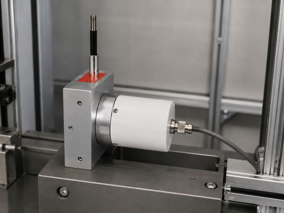
Displacement sensors detect the position, displacement or stroke movement of a machine component. They are used, for example, on presses, test benches, valves, clamping devices, linear actuators and special-purpose machines. Depending on the application, the required measuring range extends from a few tenths of a millimetre to several metres.
When selecting a sensor, the maximum measuring range is often considered first. However, this value alone is not sufficient. The mechanical coupling, linearity, repeatability, degree of protection, environmental conditions and output signal compatible with the control system are equally important.
A sensor may fully cover the required displacement range and still be unsuitable if its probe stem is subjected to lateral forces, the degree of protection is not appropriate for the machine or the output signal is susceptible to interference over a long cable. Displacement measurement must therefore be considered as a complete measuring chain consisting of the mechanics, sensor, wiring and signal evaluation.
Table of contents
- What type of displacement measurement is required?
- Which measuring principles are available?
- Correctly defining the measuring range and mechanical reserve
- Distinguishing between linearity, accuracy and repeatability
- Displacement sensor or measuring probe?
- Mechanical coupling and axial alignment
- Degree of protection and environmental conditions
- 0–10 V, 4–20 mA or a digital signal?
- Connecting a displacement sensor to a PLC
- Dynamics, response time and sampling rate
- Calibration and testing of the measuring chain
- Practical example on a hydraulic press
- Important selection criteria
- Which measuring instruments / products are suitable?
- Conclusion
- Frequently asked questions
What type of displacement measurement is required?
Before selecting the sensor, it is necessary to define which movement is actually to be measured. A slow stroke movement on a press cylinder has different requirements from fast position measurement on a test bench or the monitoring of a small valve stroke.
In particular, a distinction should be made between:
- the absolute position of a moving component,
- relative displacement between two components,
- the stroke of a cylinder or linear actuator,
- the thickness, height or distance of a workpiece,
- the position of a slide or machine table,
- valve, spring or ram movement,
- slow deformation or rapid vibrational displacement.
The direction of movement is also important. Many displacement sensors measure linearly along one axis. If a rotary or pivoting movement is converted into linear displacement by means of a linkage, the transmission ratio and direction of measurement may change across the movement range.
The installation situation should therefore be considered at the design stage as early as possible. The sensor should measure the required movement directly and should not unnecessarily include numerous joints, levers or elastic intermediate components.
Which measuring principles are available?
Different measuring principles are available for industrial displacement measurement. They differ in terms of measuring range, overall dimensions, wear, dynamic response and output signal.
| Measuring principle | Typical characteristics | Suitable applications |
|---|---|---|
| Inductive displacement sensor | Contactless electrical detection of the core position, high repeatability, external or integrated electronics | Test benches, valve stroke measurement, mechanical engineering and measuring probes |
| Potentiometric displacement transducer | Direct resistance signal, simple signal evaluation, mechanically contacting measuring element | General mechanical engineering and medium measuring ranges |
| Magnetostrictive position sensor | Absolute and wear-free position measurement, also suitable for larger strokes | Hydraulic cylinders, presses and automation |
| Draw-wire sensor | Long measuring ranges with a compact sensor unit, flexible installation arrangement | Lifting equipment, vehicle technology, telescopic systems and large machine movements |
| Optical scale | High resolution and accuracy, more sensitive to contamination and installation errors | Precision axes, measuring tables and machine tools |
| Eddy-current or capacitive sensor | Contactless measurement of very small distances and vibrational displacements | Gap measurement, runout measurement and dynamic deformation |
An inductive displacement sensor is particularly useful when small to medium displacements must be measured repeatedly and with minimal wear. The moving core is detected without an electrical sliding contact. Versions without integrated electronics additionally require a suitable carrier-frequency amplifier or demodulator.
A draw-wire sensor, by contrast, is suitable for larger movements when a long, rigid sensor cannot be accommodated within the machine design. The measuring wire is connected to the moving component and guided on a spring-loaded drum.
Correctly defining the measuring range and mechanical reserve
The specified measuring range describes the range within which the sensor provides its specified measurement values. The normal machine stroke should not utilise this range completely.
A mechanical reserve at the beginning and end of the stroke is advisable. It accounts for adjustment tolerances, thermal expansion, play, possible deviations in the end positions and brief overtravel movements. For many applications, a reserve of approximately 10 to 20 percent in relation to the normal working stroke is appropriate.
For a machine stroke of 100 mm, a sensor with an exact measuring range of 100 mm should therefore not automatically be selected. A measuring range of 120 mm, for example, may be more suitable, provided that the resulting resolution and overall size still meet the requirements of the application.
An excessively large reserve is also unfavourable. If only a 50 mm stroke is actually used with a sensor having a 500 mm measuring range, only 10 percent of the electrical output range is utilised. This reduces the practically usable resolution and increases the relative uncertainty of the complete measuring chain.
The sensor must also not be used as a mechanical end stop. The machine requires its own stops or a suitable end-position limitation to prevent the displacement transducer from being overtravelled and damaged in the event of a malfunction.
Distinguishing between linearity, accuracy and repeatability
The technical characteristics of a displacement sensor are often confused with one another. Linearity, repeatability, resolution and overall accuracy in particular describe different properties.
Linearity
The linearity deviation describes how far the actual output characteristic deviates from an ideal straight line. For a sensor with a measuring range of 100 mm and a linearity deviation of ±0.25 percent of the measuring range, the error resulting solely from linearity may be as much as ±0.25 mm.
The linearity specification normally refers to the complete specified measuring range. It does not mean that every individual measured value is accurate to within 0.25 percent of its current value.
Repeatability
Repeatability describes how closely successive measured values agree when the same position is approached several times under comparable conditions. For sorting, positioning or testing tasks, good repeatability may be more important than absolute accuracy.
A sensor can detect a position with very good repeatability while still having a constant zero-point or scaling error. This error can be corrected by adjustment or calibration, whereas poor repeatability is more difficult to compensate for.
Resolution
Resolution is the smallest change that can still be distinguished by the sensor and downstream electronics. With an analogue sensor, it is determined not only by the sensing element, but also by noise, the measuring amplifier and the resolution of the PLC analogue input.
Overall accuracy
In addition to linearity, other influences contribute to the actual measurement deviation:
- zero-point and sensitivity deviations,
- temperature drift,
- hysteresis and repeatability,
- mechanical play and alignment errors,
- resolution of the analogue input,
- electrical interference and voltage drops,
- errors in scaling and calibration.
The required accuracy should therefore be defined for the complete application. A very high sensor accuracy provides little benefit if the mechanical coupling has significantly greater play.
Displacement sensor or measuring probe?
A displacement transducer is normally permanently coupled to the moving component. A measuring probe, by contrast, has a spring-loaded guided probe stem that is placed against a surface. This makes it possible to check workpiece height, component thickness, runout or installation position, for example.
The measuring probe is particularly suitable for repetitive inspection movements. However, it requires an appropriate measuring force and a contact tip suitable for the surface. Excessive measuring force can deform thin or soft components. Insufficient force may cause the probe stem to lose contact during vibration.
The probe stem must move axially. Lateral loads can wear the guide, increase friction or cause measurement errors. In automated inspection stations, the workpiece should therefore be guided so that it does not move sideways against the probe.
The return movement must also be considered. The measuring stroke of the probe is not necessarily identical to its entire mechanical spring travel. The permissible limits of the specific version must not be exceeded.
Mechanical coupling and axial alignment
The mechanical connection between the sensor and moving component is a frequent source of error. The sensor must be able to follow the movement without being subjected to lateral forces, tilting or mechanical stress.
With a rod-shaped displacement transducer, the sensor axis and movement axis should be aligned as closely as possible. Depending on the design, small angular changes can be compensated for using ball joints or rod ends. However, a joint cannot correct a permanently offset installation.
With a rigid connection, even a minor parallel alignment error can cause the piston rod or sensor core to be subjected to lateral loads. Possible consequences include increased friction, hysteresis, mechanical wear and a shifted characteristic curve.
The mounting arrangement must also be sufficiently rigid. Thin mounting brackets or long adapters can deform under acceleration, vibration or process forces. In this case, the sensor measures not only the machine movement but also the movement of its own mounting bracket.
With draw-wire sensors, the wire must be guided out of the sensor housing in as straight a line as possible. Lateral pulling forces can place stress on the wire guide and drum. If guide pulleys are required, their diameter and alignment must be suitable for the wire being used.
Degree of protection and environmental conditions
The degree of protection indicates how well the sensor housing is protected against foreign objects, dust and water. A high IP rating is particularly important on machine tools, mobile equipment, presses and in contaminated production environments.
The required degree of protection depends on the actual exposure:
| Environment | Typical exposure | Important sensor characteristics |
|---|---|---|
| Test bench near a control cabinet | Low exposure to dust and moisture | Basic protection against contact and dust may be sufficient |
| General mechanical engineering | Dust, splash water and occasional cleaning | Frequently IP65 or IP66 |
| Machine tool | Coolant, chips, oil mist and heavy contamination | Robust housing, suitable seals and protected cable connection |
| Outdoor area or mobile machine | Rain, dirt, condensation, vibration and temperature changes | High degree of protection, corrosion-resistant materials and vibration-resistant connections |
| Temporary immersion | Direct exposure to water | Suitable IP67 or IP68 version in accordance with the specific manufacturer’s conditions |
A high degree of protection applies only to the fully assembled system. A sensor rated to IP67 may lose its protective effect if an unsuitable mating connector, an insufficiently tightened cable gland or a damaged cable is used.
In addition to moisture, temperature, vibration, shock, aggressive media and electromagnetic interference must be taken into account. With significant temperature fluctuations, the sensor, mounting bracket and machine may expand at different rates. This mechanical change can appear in the measurement result as an apparent displacement.
0–10 V, 4–20 mA or a digital signal?
The output signal must be suitable for the control system, cable length, interference environment and required resolution.
0–10 V
A voltage signal can be connected easily to many PLC analogue inputs. It is particularly suitable for short cable runs and well-controlled industrial environments.
Voltage drops, differences in ground potential and induced interference can affect the measured value. The signal ground and power supply must therefore be routed in accordance with the connection diagram.
4–20 mA
A current signal is often the more robust solution for longer cable runs and industrial environments with high levels of interference. The same current flows through the entire series circuit, meaning that cable resistances within the permissible load do not directly alter the measured value.
The range below 4 mA can additionally be used to detect certain cable or device faults. This requires the sensor and signal evaluation system to support corresponding fault behaviour.
Digital interfaces
Digital systems such as SSI, CANopen or IO-Link transmit the position value without additional analogue scaling. Depending on the interface, additional status, diagnostic or parameter data may also be available.
However, digital transmission is not automatically the best solution for every machine. The control system, cycle time, cable length, bus structure and software requirements must suit the application.
Unamplified sensor signal
Inductive displacement sensors without integrated electronics often provide a signal that must be excited, demodulated and amplified by external electronics. This solution allows flexible adaptation and can be advantageous at high temperatures because the sensitive electronics can be installed away from the measuring point.
Connecting a displacement sensor to a PLC
When connecting the sensor to a PLC, the power supply, signal type, input configuration and scaling must be compatible. Depending on the version, a 4–20 mA sensor requires an active or passive current loop. A 0–10 V sensor requires a voltage input with a common or correctly referenced signal ground.
The following applies for linear scaling:
Position = (measuring signal − signal at lower range value) / signal span × measuring range
For a displacement sensor with a range of 0 to 250 mm and an output of 4 to 20 mA, the following values apply:
- 4 mA = 0 mm
- 12 mA = 125 mm
- 20 mA = 250 mm
The raw PLC values must be converted according to the resolution of the analogue input being used. It should also be checked how the control system handles values below 4 mA, values above 20 mA and an open circuit.
Signal cables should be routed separately from motor, frequency converter and heating cables. Shielding, earthing and equipotential bonding must be implemented in accordance with the connection concept of the system. Shields connected at multiple or unsuitable points can cause equalising currents and additional interference.
Dynamics, response time and sampling rate
For slow positioning, a moderate response speed is often sufficient. If a rapid press stroke, vibrational movement or brief displacement step is to be detected, the sensor bandwidth, measuring amplifier and sampling rate must be considered together.
A high PLC sampling rate does not improve the result if the displacement sensor or measuring amplifier heavily filters the signal beforehand. Conversely, a fast sensor cannot record brief movements if the control system reads the analogue value only at long intervals.
The mechanical design also limits the dynamic response. A long, elastic coupling rod or vibrating mounting bracket can generate resonances. With measuring probes, the probe stem may briefly lose contact with the surface if the acceleration is too high.
For dynamic applications, at least the following points should therefore be defined:
- maximum travel speed,
- maximum acceleration,
- shortest relevant movement duration,
- required sensor bandwidth,
- filter setting of the signal evaluation system,
- sampling rate and storage interval.
Calibration and testing of the measuring chain
During calibration, the reading of the displacement sensor is compared with known reference positions. Depending on the measuring range and accuracy requirements, vernier callipers, dial gauges, gauge blocks, precision scales, coordinate measuring machines or laser interferometers can be used.
The test should include several points across the complete measuring range being used. Measurements in both increasing and decreasing directions are advisable so that hysteresis, play and return effects become visible.
For a sensor with an integrated 4–20 mA output, two different tests are possible:
- Mechanical testing of the sensor using defined reference displacements
- Electrical testing of the PLC scaling by simulating the current signal
The Druck UPS4E loop calibrator can output a defined 4–20 mA signal and be used to test the downstream PLC or display input. This makes it possible to check the wiring, scaling and analogue input. The mechanical function and linearity of the displacement sensor are not tested by this signal simulation.
For high accuracy requirements, testing in the installed condition may be advisable. This also includes the mounting bracket, coupling, cable and actual signal evaluation system in the assessment.
Practical example: Stroke measurement on a hydraulic press
The stroke of a hydraulic press is to be measured over a range of 0 to 250 mm. The sensor is mounted on the fixed machine structure and connected to the moving press ram by means of a joint. The output signal is 4–20 mA.
During a pressing operation, the ram is positioned at 140 mm. The expected output current is:
4 mA + (140 mm / 250 mm × 16 mA) = 12.96 mA
However, the PLC displays 145 mm at this current. For troubleshooting, the sensor is first electrically disconnected and a signal of 12.96 mA is simulated using a loop calibrator.
If the PLC continues to display 145 mm, the error is in the scaling or analogue input. If it displays the correct value of 140 mm, the displacement sensor, mechanical coupling and sensor calibration must be checked.
During the mechanical inspection, it is found that the sensor mounting bracket deflects slightly under load. The movement of the bracket is measured by the displacement sensor in addition to the actual press stroke. After a more rigid bracket is installed, the measured values are within the required tolerance.
The example shows that a deviation is not automatically caused by the sensor. The mechanical arrangement, output signal and PLC signal evaluation must be tested separately.
Important selection criteria
The following information in particular is required when selecting a displacement sensor:
- minimum, normal and maximum measuring range,
- required mechanical reserve,
- absolute position or relative displacement change,
- required accuracy, resolution and repeatability,
- travel speed and dynamic response,
- available axial and radial installation space,
- type of mechanical coupling,
- possible lateral forces and angular movements,
- temperature, moisture, dust and exposure to liquids,
- vibration and shock loads,
- required degree of protection,
- output signal or digital interface,
- power supply and cable length,
- required calibration or test certificate.
The final version should be matched to the actual machine. This is particularly important in the presence of aggressive media, potentially explosive atmospheres, high temperatures and safety-related position monitoring.
Which measuring instruments / products are suitable?
Inductive displacement transducers and measuring probes
The displacement transducers / displacement sensors / measuring probes category includes various inductive sensors, miniature displacement transducers and draw-wire sensors for mechanical engineering, test benches and automation.
The available versions differ in terms of measuring range, housing diameter, integrated or external electronics, degree of protection and accuracy.
ISM40 inductive displacement transducer
The ISM40 is a universally applicable inductive displacement transducer with integrated electronics. It is available for measuring ranges of up to 200 mm and can also be supplied as a measuring probe.
With an IP66 degree of protection, the series is suitable for industrial machine environments where dust and powerful water jets must be considered. The specific version is selected according to the measuring range, accuracy and required output signal.
ISM34 miniature displacement transducer
The ISM34 combines a compact design with integrated electronics. The housing diameter is approximately 10 mm, while measuring ranges of up to 20 mm are available.
The miniature version is particularly suitable for confined installation spaces, small test benches, assembly fixtures and compact machine modules.
ISM21 and ISM26 with external electronics
The ISM21 covers measuring ranges of up to 20 mm and is also available as a measuring probe. For larger displacements, the ISM26 is available with measuring ranges of up to 200 mm. Both series operate with external electronics and, depending on the version, are protected up to IP68.
The spatial separation of sensor and electronics can be useful where installation space at the measuring point is limited or where the electronics must be installed away from elevated temperatures and severe environmental influences.
IWS12 draw-wire sensor
The IWS12 draw-wire sensor is suitable for measuring ranges from 100 to 3,000 mm. It is available with outputs including 0–10 V, 4–20 mA, potentiometer or SSI and has an IP67 degree of protection.
The design is particularly suitable for larger strokes where a long rod-shaped sensor cannot be integrated into the machine. The measuring wire must be guided in a straight line and without lateral loading.
Druck UPS4E loop calibrator
The Druck UPS4E is suitable for the electrical testing of displacement sensors and transmitters with a 4–20 mA output. It can measure or simulate current signals and provide a 24 V loop power supply.
This allows the signal transmission, wiring and scaling of the PLC input to be tested separately from the mechanical displacement measurement.
Conclusion: The appropriate displacement sensor is not selected solely according to its measuring range
The measuring range is an important selection criterion, but only one part of the complete design process. Linearity, repeatability, mechanical coupling, degree of protection, dynamic response and output signal together determine whether the sensor will provide reliable values in the machine.
Inductive displacement transducers are often suitable for short to medium measuring ranges and high repeatability. Measuring probes are useful for contact-based inspection tasks, while draw-wire sensors can detect larger movements with a compact design.
The sensor must be installed in axial alignment and as free from lateral forces as possible. Separate machine stops protect it against overtravel. In harsh environmental conditions, not only the sensor housing but also the connector, cable and mechanical feedthrough must be selected appropriately.
During commissioning, the mechanical displacement and electrical signal path should be tested separately. This makes it possible to determine whether a deviation is caused by the sensor, installation, wiring or PLC scaling.
Frequently asked questions about selecting and installing displacement sensors
How much reserve should the measuring range include?
The normal working stroke should not utilise the specified measuring range completely. A reserve of approximately 10 to 20 percent is often advisable. The specific reserve depends on end-position tolerances, temperature, dynamic response and possible overtravel.
What is the difference between linearity and repeatability?
Linearity describes the deviation of the sensor characteristic from an ideal straight line. Repeatability describes how consistently the same position is indicated over several measurements.
Is an inductive displacement sensor wear-free?
The inductive measuring principle operates without an electrical sliding contact and is therefore generally low-wear. With a measuring probe, however, the probe stem, guide and return mechanism remain mechanically stressed components.
When is 4–20 mA preferable to 0–10 V?
A 4–20 mA signal is often more robust over longer cable runs and in industrial environments with high levels of interference. A 0–10 V signal is well suited to short cables and existing voltage inputs.
Can a displacement sensor be used as an end stop?
No. The sensor should not absorb the mechanical end force of the machine. Separate stops or end-position limiters must prevent the permissible sensor travel from being exceeded.
Why does the displacement value fluctuate while the motor is running?
Possible causes include electromagnetic interference, differences in potential, vibration, an unstable mounting bracket or unsuitable cable routing. The sensor, mechanical arrangement and electrical signal path should be tested separately.
Can the degree of protection be reduced by the connector?
Yes. The specified degree of protection applies only with fully assembled and suitable connections. An incorrect mating connector, loose cable gland or damaged cable can reduce the protective effect.
How is a displacement sensor calibrated?
The sensor is compared at several positions with a suitable length reference. Depending on the required accuracy, vernier callipers, dial gauges, gauge blocks, precision scales, coordinate measuring machines or laser interferometers may be used.
Which information is required for selection?
The required information includes the measuring range, necessary reserve, accuracy, repeatability, dynamic response, installation space, mechanical coupling, lateral forces, environmental conditions, degree of protection, output signal, power supply, cable length and required calibration.