


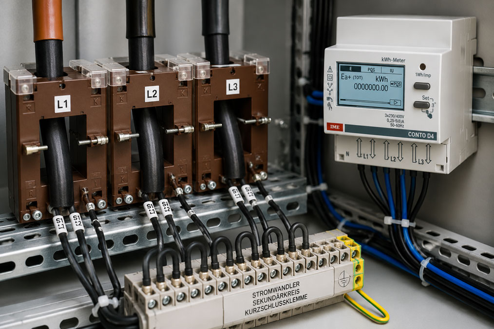
Current transformers are used in electrical installations to convert high currents into a smaller, measurable secondary current. Typical secondary currents are 1 A or 5 A. This allows energy meters, measuring instruments, power analyzers or protection devices to evaluate currents that could not be measured directly, or only with considerable effort.
As practical as current transformers are, safe handling is just as important. A conventional current transformer must never be operated with an open secondary circuit during operation. If current flows through the primary conductor and the secondary circuit is interrupted, dangerously high voltages can occur. This can endanger people, damage insulation, thermally stress the current transformer and destroy connected devices. This article explains why an open secondary circuit is problematic, how current transformers are safely short-circuited and what must be observed during maintenance, replacement and commissioning.
Suitable products and solutions can be found, among others, in the categories current transformers / window-type current transformers, split-core current transformers and energy meters.
Table of contents
- Basic principle: What does a current transformer do?
- What is the secondary circuit of a current transformer?
- Why an open secondary circuit can become dangerous
- Why high voltages can occur with an open secondary circuit
- Short-circuiting current transformers: What does this mean in practice?
- Short-circuit terminals and test terminals: Why they are useful
- Replacing or maintaining a measuring instrument: Correct procedure
- Current transformers on energy meters and measuring instruments
- 1 A or 5 A: Why the secondary current must match the measuring chain
- Burden, cable length and connection errors
- Split-core current transformers: Safe retrofitting, but correct connection required
- Typical errors when handling current transformers
- Suitable products for current measurement and energy measurement
- Practical example: Replacing a measuring instrument during operation
- Conclusion: Operate current transformers only with a closed or short-circuited secondary circuit
- FAQ: Frequently asked questions about open secondary circuits in current transformers
Basic principle: What does a current transformer do?
A current transformer reduces a high primary current to a smaller secondary current. The primary current flows through the conductor or busbar that passes through the current transformer. On the secondary side, the transformer provides a proportional current that can be evaluated by a measuring instrument, energy meter or protection device.
A typical example is a current transformer with a ratio of 500/5 A. If 500 A flows on the primary side, the current transformer supplies 5 A on the secondary side. At 250 A, it would correspondingly supply 2.5 A. This allows a measuring instrument to work with a standardized input even though significantly higher currents flow in the installation.
Current transformers are used in low-voltage distributions, control cabinets, energy monitoring systems, load management systems, machines, main distribution boards and sub-distribution boards. They are particularly important when direct current measurement is not possible or not practical. At higher currents, direct measurement through the measuring instrument would be complex, expensive and unfavorable from a safety perspective.
The current transformer is not simply a sensor, but an electromagnetic component. Its behavior depends on the secondary circuit being connected correctly. This is exactly why an open secondary circuit is so critical.
What is the secondary circuit of a current transformer?
The secondary circuit is the circuit on the output side of the current transformer. It consists of the secondary terminals of the transformer, the connection cables, any short-circuit terminals or test terminals and the connected measuring instrument. This circuit must be closed during operation so that the current transformer can safely supply its secondary current.
With a current transformer with a 5 A output, a current of 5 A flows in the secondary circuit at nominal current. With a 1 A transformer, the corresponding value is 1 A. The measuring instrument represents a defined burden. The burden is the load that the current transformer must drive on the secondary side. This includes not only the input of the measuring instrument, but also cables, terminals and contact resistances.
If the secondary circuit is opened, this current can no longer flow. This fundamentally distinguishes the current transformer from many other measurement signals. With a voltage output, an open input is often uncritical. With a conventional current transformer, however, an open secondary circuit is a dangerous operating condition.
Therefore, the basic rule is: A current transformer may only be operated if the secondary circuit is either closed by a suitable measuring instrument or safely short-circuited. It must not be open during operation.
Why an open secondary circuit can become dangerous
If current flows on the primary side and the secondary circuit is open, the current transformer still attempts to generate a current on the secondary side. However, because the circuit is interrupted, this current cannot flow. The result can be a sharply rising secondary voltage.
This voltage can become dangerous for people. At the same time, it can stress the insulation of the current transformer, the connection terminals or the cables. The transformer itself can also be damaged by increased magnetic stress and heating. In unfavorable cases, the current transformer can be permanently damaged or lose its accuracy.
An open secondary circuit is particularly tricky because the primary current continues to flow and the installation appears to operate normally. The problem occurs on the measurement side. If, for example, an energy meter is removed without the current transformer having been short-circuited beforehand, the dangerous condition can occur immediately.
For this reason, work on current transformer secondary circuits must be carefully planned. Before disconnecting a measuring instrument, it must be ensured that the secondary circuit of the transformer remains safely closed. In practice, this is done using short-circuit terminals, test terminals or suitable short-circuit bridges.
Why high voltages can occur with an open secondary circuit
A current transformer operates according to the transformer principle. The primary current generates a magnetic field in the core. The secondary current counteracts this magnetic field. As long as the secondary circuit is closed, a controlled operating state is established. The transformer supplies its secondary current to the measuring instrument.
If the secondary circuit is opened, this compensating secondary current is missing. The magnetic flux in the core can increase significantly. As a result, very high voltages can be induced on the secondary side. These voltages must not be confused with the normal secondary current of 1 A or 5 A. This is a dangerous fault condition.
The level of the voltage depends on several factors: the primary current, the transformer type, the core, the ratio, the condition of the transformer and the connected cables. It should therefore never be assumed that an open secondary circuit is “probably harmless”. The safe approach is always not to open the secondary circuit during operation.
In addition, the transformer core can become saturated or thermally stressed. This can later lead to measurement errors even after the secondary circuit has been closed again. A current transformer that has been operated open should therefore not simply be regarded as undamaged, but should be professionally assessed.
Short-circuiting current transformers: What does this mean in practice?
Short-circuiting a current transformer means that the secondary terminals of the transformer are directly connected to each other using a suitable connection. This keeps the secondary circuit closed even if the measuring instrument is removed, replaced or disconnected. The current transformer then operates against a very low resistance and can safely carry its secondary current.
Important: A current transformer is not short-circuited on the primary side, but on the secondary side. The primary side is the conductor or busbar that passes through the transformer. The short-circuiting measure concerns the secondary terminals of the transformer or the short-circuit terminals provided for this purpose in the measuring circuit.
In practice, the short circuit should not be improvised. A loose wire bridge in an unsuitable location, poorly tightened terminals or unclear assignment of secondary cables can be dangerous. Dedicated short-circuit terminals or test terminal blocks are better, as they allow the secondary circuits to be clearly and safely bridged.
A correctly short-circuited current transformer can be operated without a measuring instrument connected. This is important, for example, during maintenance, replacement or temporary shutdown of a measuring instrument. Nevertheless, it must be clearly documented which transformer has been short-circuited and when the measuring chain will be put back into operation.
Short-circuit terminals and test terminals: Why they are useful
Short-circuit terminals and test terminal blocks are particularly useful when working with current transformers because they can close the secondary circuit in a controlled and traceable manner. They make it possible to replace measuring instruments or carry out test work without operating the current transformer with an open secondary circuit.
In energy distribution systems, control cabinets and measuring panels, such terminals are often used to make maintenance and testing safer. The technician can bridge the transformer circuit before disconnecting a measuring instrument. After replacement, the new device can be connected and the bridge can be removed again in a controlled manner.
The advantage is not only safety, but also clarity. If several current transformers are installed for L1, L2 and L3, it must be clearly visible which secondary cables belong to which transformer. Test terminals help avoid mix-ups and keep the measuring circuits clearly structured.
| Component | Function | Why it is important |
|---|---|---|
| Short-circuit terminal | Safely short-circuits the secondary circuit of a current transformer | Prevents an open secondary circuit during maintenance or replacement |
| Test terminal | Enables testing and separation of defined measuring circuits | Facilitates service and troubleshooting |
| Terminal marking | Clearly assigns transformer, phase and measuring instrument | Reduces the risk of mix-ups |
| Documentation | Describes wiring, ratio and connection | Helps during maintenance, replacement and later troubleshooting |
Especially in measuring installations that are regularly tested or expanded, short-circuiting and testing options should be planned from the beginning. Subsequent improvisations are not a good solution in current transformer circuits.
Replacing or maintaining a measuring instrument: Correct procedure
A typical case is the replacement of an energy meter, power analyzer or measuring instrument during operation. The installation is intended to continue running, but the measuring instrument must be replaced. This is exactly where the risk arises that the secondary circuits of the current transformers are unintentionally opened.
Before disconnecting the measuring instrument, the associated current transformers must be safely short-circuited on the secondary side. Only once the secondary circuit is closed may the cables be removed from the measuring instrument. After installing the new device, the wiring is checked, the phase assignment is verified and only then are the short-circuit bridges removed again.
This work must be carried out carefully. In three-phase measurements, there are usually several current transformers. Each transformer circuit must be considered individually. It is not enough to place a bridge “somewhere”. What matters is that exactly the secondary terminals of the affected transformer are closed.
Work on such measuring circuits may only be carried out by qualified electricians or under their responsibility. The company safety rules, approvals and installation documentation must be observed. Safe handling of current transformers is not a secondary detail, but an essential part of electrical work safety.
Current transformers on energy meters and measuring instruments
Current transformers are frequently used together with energy meters, multifunction measuring instruments or power analyzers. The energy meter then does not measure the primary current directly, but the secondary current of the transformer. For the display to be correct, the transformer ratio must be correctly set in the measuring instrument.
If a current transformer has a ratio of 500/5 A, for example, the energy meter must be parameterized accordingly. If the wrong ratio is entered, consumption values, power values and currents will be incorrect. This is a common error in energy measurements in control cabinets and sub-distribution boards.
In addition to parameterization, safe wiring is also decisive. The secondary cables of the current transformers must be clearly assigned to the correct phases. Current path and voltage path must match. If the current transformer from L1 is connected, but the associated voltage from another phase is evaluated, implausible power and energy values will result.
Energy meters such as the CONTO D4 are used for applications with external current transformers. In such measuring chains, current transformers, secondary current, transformer ratio, wiring and short-circuiting options must be planned carefully.
1 A or 5 A: Why the secondary current must match the measuring chain
Many current transformers provide either 1 A or 5 A on the secondary side. Which value is useful depends on the measuring instrument, cable length, burden and system concept. It is important that the current transformer and measuring instrument match. A measuring instrument with a 5 A input must not accidentally be connected to a 1 A transformer and parameterized incorrectly.
5 A current transformers are widely used in many installations. With longer secondary cables, however, 1 A can offer advantages because cable losses are lower. The measuring instrument must support the corresponding input. The selection should therefore not be made in isolation, but should always be considered as a complete measuring chain.
The safety issue regarding an open secondary circuit remains relevant for both variants. A 1 A current transformer is not automatically harmless just because its secondary rated current is lower. If the secondary circuit is opened, a dangerous voltage can also occur here. The basic rule remains the same: The secondary circuit must be closed or short-circuited during operation.
| Secondary current | Typical use | Important note |
|---|---|---|
| 1 A | Longer secondary cables, reduced cable losses | Measuring instrument must support 1 A input or suitable parameterization |
| 5 A | Widely used in conventional measuring installations | Burden and cable length must be taken into account |
| 4–20 mA | Current transformer with integrated transmitter | Different signal principle than conventional 1 A or 5 A current transformers |
Especially when replacing measuring instruments or current transformers, it should therefore be checked whether the secondary current, ratio and parameterization really match.
Burden, cable length and connection errors
The burden describes the load that the current transformer must drive on the secondary side. It consists of the input of the measuring instrument, cables, terminals and contact resistances. If the burden is too high, the current transformer may operate outside its intended conditions. This can cause measurement errors.
Long cables increase the burden. Especially with 5 A current transformers, cable losses can be more significant. Therefore, for longer distances between current transformer and measuring instrument, it should be checked whether the selected transformer, secondary current and cable cross-section are suitable.
Poor terminal connections are also problematic. Loose terminals, corroded contacts or poorly tightened screw connections can increase the burden and, in unfavorable cases, cause an interruption. In current transformer circuits, this is particularly critical because an interruption during operation can lead to an open secondary circuit.
Careful wiring is therefore part of safety. Secondary cables should be clearly marked, mechanically secured and connected according to the wiring diagram. During commissioning, it should not only be checked whether measured values are displayed, but also whether the wiring has been carried out professionally and is permanently safe.
Split-core current transformers: Safe retrofitting, but correct connection required
Split-core current transformers are frequently used when measurements need to be retrofitted without disconnecting the primary conductor. They can be placed around an existing conductor or busbar. This is particularly practical for existing installations, energy monitoring, retrofits and temporary measuring tasks.
However, the same rule applies to split-core current transformers: The secondary circuit must be connected correctly. If a split-core transformer is installed while current is flowing on the primary side, the secondary circuit must be safely connected or short-circuited. The simple mechanical installation must not lead to the electrical safety rules being neglected.
In addition, the correct installation direction, clean closing of the core and correct phase assignment must be observed for split-core transformers. If the core is not properly closed or the transformer is installed the wrong way round, measured values can become implausible. With several transformers for L1, L2 and L3, the assignment to the voltage paths of the measuring instrument must be correct.
Split-core current transformers such as those in the split-core current transformers category are particularly suitable for retrofits. Nevertheless, the installation should be planned just as carefully as with conventional window-type current transformers.
Typical errors when handling current transformers
A common error is disconnecting a measuring instrument without short-circuiting the current transformers on the secondary side beforehand. This can directly lead to an open secondary circuit. This is particularly dangerous if the installation remains in operation and load current flows on the primary side.
Another error is assuming that an unconnected measuring instrument is automatically unproblematic. With a current transformer, the opposite is true. If the primary conductor carries current, the secondary side must be closed. An unused current transformer should therefore not be left open, but should be safely short-circuited or properly taken out of operation.
Mixing up secondary cables is also common. If the transformers of L1, L2 and L3 are swapped in a three-phase system, the current and voltage paths no longer match. This results in incorrect power values, negative energy or implausible displays. The measurement can then technically function, but be incorrect from a metrological point of view.
Other problematic issues include missing markings, missing short-circuit terminals, excessively long secondary cables, incorrect transformer ratios, incorrect parameterization of the measuring instrument and unsuitable burdens. Many measurement problems are not caused by defective components, but by an incompletely planned measuring chain.
| Error | Possible consequence | Correct procedure |
|---|---|---|
| Measuring instrument removed without short-circuit bridge | Open secondary circuit, dangerous voltage possible | Short-circuit transformer on the secondary side beforehand |
| Unused current transformer left open | Dangerous condition with primary current | Safely short-circuit secondary side or properly take out of operation |
| L1/L2/L3 transformers swapped | Incorrect power and energy | Assign current and voltage paths phase-correctly |
| Incorrect transformer ratio parameterized | Measured values systematically incorrect | Set ratio correctly in the measuring instrument |
| No short-circuit terminals provided | Maintenance and replacement become riskier | Plan short-circuit or test terminals |
The most important rule remains: Before any work on current transformer secondary circuits, it must be clear whether primary current is flowing and how the secondary circuit remains safely closed.
Suitable products for current measurement and energy measurement
For conventional measuring tasks in low-voltage distributions, window-type current transformers and current transformers for cables or busbars are suitable. They are used in combination with energy meters, multifunction measuring instruments or power analyzers.
For retrofits without disconnecting the primary conductor, split-core current transformers are a useful solution. Examples include current transformers such as the TRA812 or other split-core transformers for low-voltage networks.
For large conductors or busbars, suitable current transformers such as the TAS 127 can be used. The selection depends on primary current, conductor opening, accuracy class, burden, secondary current and installation situation.
For evaluating the measured values, energy meters with current transformer connection are suitable, for example the CONTO D4. If a standardized output signal is required instead of a conventional 1 A or 5 A secondary signal, current transformers with integrated transmitters such as the TT35 may be of interest.
Regardless of the product, the following applies: current transformer, measuring instrument, short-circuiting option, wiring and parameterization must be considered as a complete measuring chain. Only then is the measurement safe, plausible and permanently reliable.
Practical example: Replacing a measuring instrument during operation
In a low-voltage distribution board, an older energy meter is to be replaced by a modern measuring instrument with a communication interface. The installation supplies several consumers and should not be switched off during the work if possible. The currents are recorded via three current transformers, each with a secondary current of 5 A.
Before disconnecting the old measuring instrument, the qualified electrician checks the wiring and identifies the secondary circuits of the three current transformers. The secondary circuits are safely bridged using the existing short-circuit terminals. Only then are the cables on the old measuring instrument disconnected.
If the measuring instrument were removed without prior short-circuiting, the secondary circuits of the current transformers would be open while load current continues to flow on the primary side. This could cause dangerous voltages to occur. This is exactly why the short-circuit bridge is mandatory before disconnecting.
After installing the new measuring instrument, the current paths and voltage paths are connected phase-correctly. The transformer ratio is parameterized in the measuring instrument. The short-circuit bridges are then removed in a controlled manner. Afterwards, the measured values are checked for plausibility: current values, phase assignment, active power, sign and energy counting must match the installation.
The example shows that safe operation of current transformers does not begin with the product alone, but with the correct procedure. The secondary circuit must always be closed either via the measuring instrument or via a safe short-circuit connection.
Conclusion: Operate current transformers only with a closed or short-circuited secondary circuit
A current transformer is a proven and important component for current measurement, energy measurement and network monitoring. At the same time, it requires safe handling. The most important principle is: A conventional current transformer must not be operated with an open secondary circuit while primary current is flowing.
An open secondary circuit can generate dangerously high voltages, endanger people, damage insulation and stress the current transformer itself. Therefore, the secondary circuit must be safely short-circuited during maintenance, replacement or temporary operation without a measuring instrument.
For safe and reliable measuring installations, current transformers, energy meters, short-circuit terminals, cable lengths, burden, transformer ratio and documentation should be planned together. Suitable solutions can be found in the areas of current transformers / window-type current transformers, split-core current transformers and energy meters.
FAQ: Frequently asked questions about open secondary circuits in current transformers
Why must the secondary circuit of a current transformer not be open?
If current flows on the primary side and the secondary circuit is open, the current transformer can generate dangerously high voltages on the secondary side. This can endanger people, damage insulation and stress the transformer itself.
What does “short-circuiting a current transformer” mean?
It means safely connecting the secondary terminals of the current transformer. This keeps the secondary circuit closed even if a measuring instrument is removed or replaced.
Can a current transformer be operated without a measuring instrument?
Yes, but only if the secondary circuit is safely short-circuited. A conventional current transformer must not be operated open while primary current is flowing.
When must short-circuit terminals be used?
Short-circuit terminals are particularly useful when measuring instruments, energy meters or power analyzers are maintained, tested or replaced. They allow the current transformer secondary circuits to be safely short-circuited.
What happens if an energy meter is disconnected without short-circuiting the current transformers?
The secondary circuits of the current transformers can then be opened while current continues to flow on the primary side. This can generate dangerous voltages. For this reason, the transformers must be short-circuited on the secondary side beforehand.
Does the danger also apply to 1 A current transformers?
Yes. A 1 A current transformer must also not be operated open while primary current is flowing. The lower secondary rated current does not mean that an open secondary circuit is harmless.
What is the burden of a current transformer?
The burden is the load on the secondary side of the current transformer. This includes the measuring instrument, cables, terminals and contact resistances. An excessive burden can cause measurement errors.
Can you simply disconnect a current transformer?
No. Before disconnecting, it must be checked whether primary current is flowing. If so, the secondary circuit must first be safely short-circuited. Such work may only be carried out professionally by qualified persons.
Why do energy meters with current transformers sometimes show incorrect values?
Common causes are an incorrect transformer ratio, swapped phases, incorrect current direction, incorrect assignment of current and voltage paths, excessive burden or connection errors.
Which products are suitable for safe current transformer measurement?
Suitable products include window-type current transformers, split-core current transformers, suitable energy meters with current transformer connection and current transformers with integrated transmitters such as the TT35 if a standardized output signal is required.