


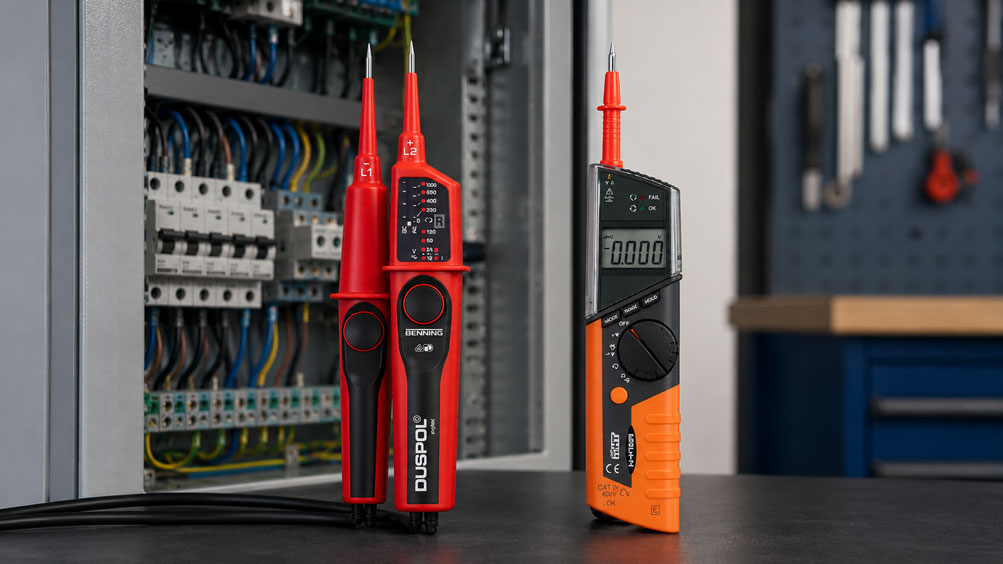
Digital multimeters and two-pole voltage testers are often used for similar tasks in practice. Both devices can indicate voltage, and both are part of the basic equipment in electrical engineering, building services, maintenance and training. Nevertheless, they are not simply interchangeable.
A digital multimeter is a versatile measuring instrument for voltage, current, resistance, continuity, frequency and other electrical quantities. A two-pole voltage tester, on the other hand, is specifically designed to check voltage quickly, robustly and safely between two points. Especially when verifying absence of voltage, the two-pole voltage tester is the right tool.
This article explains when a digital multimeter is useful, when a two-pole voltage tester should be used, which typical measurement errors occur and why choosing the right device is crucial for electrical safety.
Table of contents
- Basics: Multimeter and voltage tester compared
- What can a digital multimeter do?
- What can a two-pole voltage tester do?
- Verifying absence of voltage: Why the two-pole voltage tester is important
- Measuring voltage: When the multimeter is useful
- Typical measurement errors with a digital multimeter
- High-impedance measurement and phantom voltages
- Load connection on a two-pole voltage tester
- Observe measurement category, voltage range and safety
- Continuity testing, resistance and troubleshooting
- Use in control cabinets and maintenance
- Typical errors in training and practice
- Table: Which device for which task?
- Practical example: Checking voltage correctly in a control cabinet
- Suitable devices for practical use
- Conclusion: Not either/or, but using each device correctly
- FAQ: Frequently asked questions about multimeters and voltage testers
Basics: Multimeter and voltage tester compared
A digital multimeter and a two-pole voltage tester serve different purposes. The multimeter is a universal measuring instrument. It displays measured values as accurately as possible and is suitable for diagnostics, troubleshooting, comparative measurements and electrical measuring tasks involving different measured quantities.
The two-pole voltage tester, by contrast, is a test instrument for fast and safe voltage testing. It is connected with two test probes between two points and indicates whether voltage is present. Many devices also offer functions such as continuity testing, phase sequence indication, polarity indication or load connection.
The most important difference lies in the application: When an accurate measured value is required, the digital multimeter is often the better tool. When it must be safely checked whether voltage is present in an electrical system or not, the two-pole voltage tester is the right choice.
In practice, both devices belong together. The voltage tester is used for safe voltage testing, while the multimeter is used for detailed measurement and troubleshooting.
What can a digital multimeter do?
Depending on the model, a digital multimeter can measure various electrical quantities. Typical functions include AC voltage, DC voltage, current, resistance, continuity, diode test, frequency, capacitance or temperature. This makes it very versatile.
In maintenance, for example, a multimeter is used to check supply voltages, test 24 V DC circuits, measure batteries, examine sensor cables or test resistances and continuity.
The advantage lies in accuracy and versatility. A multimeter not only indicates whether voltage is present, but also how high it is. This is important when target values must be checked or deviations evaluated.
The disadvantage: A multimeter must be set correctly and connected properly. Incorrect measuring range, wrong socket, defective fuse or unsuitable measurement category can lead to dangerous situations or incorrect measurement results.
What can a two-pole voltage tester do?
A two-pole voltage tester is designed for voltage testing between two active measuring points. It is used, for example, between phase conductor and neutral conductor, between phase conductor and protective conductor or between two phase conductors.
Many two-pole voltage testers indicate voltage ranges via LEDs or a display. Depending on the model, they can also distinguish between AC and DC voltage, indicate polarity, test continuity or detect phase sequence.
The two-pole design is decisive. Unlike single-pole phase testers, it does not rely only on capacitive or body-related indication, but actually tests between two points. This makes the result significantly more reliable.
For work on electrical systems, the two-pole voltage tester is therefore a central test instrument. It is not intended to completely replace a multimeter, but to complement it in safety-relevant situations.
Verifying absence of voltage: Why the two-pole voltage tester is important
Before starting work on electrical systems, it must be clearly verified whether the relevant part of the system is free of voltage. A suitable two-pole voltage tester should be used for this task.
The reason is simple: When verifying absence of voltage, the priority is not the most accurate measured value possible, but a safe and clear statement. It must be ruled out that dangerous voltage is still present, for example due to backfeed, incorrect assignment, auxiliary voltages or residual voltage.
A digital multimeter can measure voltage, but it is not the preferred solution for safely verifying absence of voltage. Incorrect settings, wrong socket, high-impedance measurement, defective fuse or unsuitable use can lead to misinterpretation.
A two-pole voltage tester is more robust, faster and better suited for this test. It is important that the device is checked for proper function before and after the test and that it matches the voltage range and measurement category of the system.
Measuring voltage: When the multimeter is useful
A digital multimeter is useful when the exact voltage level must be known. This is the case, for example, when a 24 V DC supply only delivers 19 V, a power supply unit is checked or a voltage drop on a cable must be evaluated.
The multimeter is also often the right tool for troubleshooting controls, sensors, batteries, power supplies or electronic assemblies. It provides accurate measured values and makes deviations visible.
Examples include checking a 230 V supply, checking a 24 V control voltage, measuring a voltage drop at a terminal or checking a battery in a control cabinet.
It is important that the multimeter is set correctly. Measuring function, measuring range, socket assignment, test leads and measurement category must match the application.
Typical measurement errors with a digital multimeter
A common error is selecting the wrong measuring function. If, for example, current instead of voltage is selected, the measuring instrument can cause a short circuit when connected to a voltage source. This can damage the device and create dangerous situations.
Another common error is using the wrong socket. Many multimeters have separate sockets for voltage/resistance measurement and current measurement. If the test lead is still plugged into the current socket while voltage is to be measured, there is a risk of short circuit.
The wrong measuring range can also be problematic. Modern multimeters often have automatic range selection, but the measuring function must still clearly match the task. AC and DC in particular must not be confused.
Another point is the device fuse. If the internal fuse for current measurement has blown, a current measurement may appear faulty. During voltage measurements, a high-impedance input can also indicate phantom voltages that immediately collapse under load.
High-impedance measurement and phantom voltages
Digital multimeters often have a very high input resistance. This is beneficial for many measuring tasks because the circuit is hardly loaded. At the same time, however, it can cause capacitively coupled or induced voltages to be displayed.
Such phantom voltages can occur, for example, on long cables routed in parallel. The multimeter then indicates a voltage even though there is no load-bearing energy source behind it.
This can be confusing during troubleshooting. The user may see 80 V or 120 V on a line that is actually switched off and suspect a fault. Under load, however, this voltage immediately collapses.
A two-pole voltage tester with load connection or lower impedance can help classify such voltages more reliably. Nevertheless, the measurement must always match the situation and the safety requirement.
Load connection on a two-pole voltage tester
Many two-pole voltage testers have a load connection function. This briefly applies a stronger load to the measuring point. It can help distinguish coupled or high-impedance phantom voltages from an actual load-bearing voltage.
If an indicated voltage collapses when the load is connected, this suggests a non-load-bearing residual or coupled voltage. If the voltage remains, it is more likely to be a real voltage source.
However, the load connection must only be used according to the device manual and within the permissible voltage range. It is not a substitute for safe working, but an aid for better assessment of the measuring situation.
This function can be very helpful in maintenance, especially when unclear voltage indications occur on long cables, in control cabinets or in control circuits.
Observe measurement category, voltage range and safety
When carrying out measurements on electrical systems, the measuring instrument must be suitable for the measuring point. Key factors include nominal voltage, overvoltage category, environment, energy content of the system and the condition of the test leads.
Measurement categories such as CAT II, CAT III or CAT IV describe for which areas and transient loads a measuring instrument is designed. A device for simple electronics measurements is not automatically suitable for measurements in building installations or industrial distribution systems.
The test leads are also relevant to safety. Damaged insulation, missing finger guards, unsuitable probes or unsuitable categories can be dangerous.
Before every measurement, it should therefore be checked whether the device, test leads, voltage range and measurement category match the application. If devices or leads are damaged, measurements must not be continued.
Continuity testing, resistance and troubleshooting
A digital multimeter is often very practical for continuity and resistance measurements. It can test cables, fuses, switch contacts, relay contacts or simple resistors.
It is important that resistance and continuity measurements are carried out only on de-energised circuits. If voltage is present, the measuring instrument can be damaged and the measurement is not meaningful.
Many two-pole voltage testers also have a continuity function. This is helpful for simple tests, but it does not always replace the more accurate resistance measurement with a multimeter.
For systematic troubleshooting, the following applies: First safely verify absence of voltage, then use the suitable measuring method to test continuity, resistance or signal.
Use in control cabinets and maintenance
In control cabinets, both devices are often used one after the other. The two-pole voltage tester is used to safely check whether voltage is present or whether a part of the system is de-energised. The digital multimeter is then used to measure values more accurately.
Typical tasks include checking 230 V AC supply, 400 V three-phase current, 24 V DC control voltage, power supplies, fuses, relays, contactors, sensor cables and signals.
A two-pole voltage tester is particularly fast when checking whether voltage is present at terminals. A multimeter is better when an exact value, a voltage drop or a resistance value is required.
In maintenance, choosing the right device saves time and reduces misinterpretation. Those who use both devices correctly find faults faster and work more safely.
Typical errors in training and practice
In training, work often begins with the multimeter because it covers many measured quantities. This sometimes creates the impression that a multimeter is the right device for every electrical test. That is not correct.
It is particularly dangerous to attempt to verify absence of voltage using only an incorrectly set multimeter or a single-pole phase tester. For safety-relevant tests, the suitable test instrument must be used.
Another error is evaluating measured values without context. An indicated voltage does not automatically mean that a load-bearing voltage is present. Conversely, a missing indication must not be interpreted as safety without further checking.
It is therefore important not only to know how to operate measuring instruments, but also to understand their limitations.
Table: Which device for which task?
| Task | Suitable device | Why? |
|---|---|---|
| Verify absence of voltage | Two-pole voltage tester | Designed for safe and clear voltage testing |
| Measure exact voltage level | Digital multimeter | Displays precise measured values and deviations |
| Evaluate phantom voltages | Two-pole voltage tester with load connection | Loads the measuring point and helps with classification |
| Check 24 V DC power supply | Digital multimeter | Accurate voltage measurement and troubleshooting possible |
| Pre-check 230 V or 400 V | Two-pole voltage tester | Fast check for existing voltage |
| Check continuity | Digital multimeter or voltage tester with continuity function | Depending on accuracy requirement and application |
| Measure resistance | Digital multimeter | Suitable for resistance values and comparative measurements |
| Check phase sequence | Two-pole voltage tester with phase sequence indication | Many devices offer direct phase sequence testing |
| Troubleshooting electronics | Digital multimeter | Versatile measuring functions and accurate display |
| Fast check at terminals | Two-pole voltage tester | Robust, fast and practical |
Practical example: Checking voltage correctly in a control cabinet
A power supply unit is to be replaced in a control cabinet. Before starting work, the system is isolated. It must then be checked whether the relevant part of the system is actually free of voltage.
First, the two-pole voltage tester is checked on a known voltage source. Then absence of voltage is verified on all poles at the relevant terminals. Afterwards, the voltage tester is checked again on a known voltage source to ensure that the device functioned during the test.
Only then is further work carried out with the digital multimeter. It is used to check the new power supply after installation, accurately measure the 24 V DC output voltage and check possible voltage drops at the terminals.
The example shows: The voltage tester is the right device for the safety-relevant test. The multimeter is the right device for accurate measurement and diagnostics.
Suitable devices for practical use
For safe voltage testing, two-pole voltage testers such as DUSPOL digital as well as suitable voltage testers from the HT7, HT8 or C.A 771 series are suitable. The decisive factors are the appropriate voltage range, suitable measurement category, robust test probes and a clear display.
For detailed measurements and troubleshooting, digital multimeters such as HT712 or comparable multimeters with a suitable measurement category, appropriate measuring ranges and safe test leads are suitable.
Depending on the application, compact voltage testers such as HT10 can also be useful for simple preliminary checks or supplementary inspections. However, they do not automatically replace the two-pole voltage tester for safety-relevant tests.
The best equipment therefore does not consist of just one device, but of a sensible combination: two-pole voltage tester for safe voltage testing and digital multimeter for accurate measured values and diagnostics.
Conclusion: Not either/or, but using each device correctly
Digital multimeters and two-pole voltage testers are not direct competitors. They perform different tasks and complement each other in practice.
The two-pole voltage tester is the right device when voltage must be checked safely or absence of voltage must be verified. The digital multimeter is the right device when accurate measured values, diagnostic functions or additional electrical measured quantities are required.
Those who use both devices correctly avoid measurement errors, reduce misinterpretations and increase safety when working on electrical systems. The decisive factor is not only the device itself, but also the suitable measurement category, correct operation and a clear understanding of the measuring task.
FAQ: Frequently asked questions about multimeters and voltage testers
What is the difference between a digital multimeter and a two-pole voltage tester?
A digital multimeter is a versatile measuring instrument for various electrical quantities. A two-pole voltage tester is specifically designed for fast and safe voltage testing between two points.
When do you use a two-pole voltage tester?
A two-pole voltage tester is used when it needs to be checked whether voltage is present or when absence of voltage must be safely verified.
When is a digital multimeter better?
A digital multimeter is better when accurate measured values are required, for example for voltage drop, resistance, continuity, battery voltage, power supply testing or troubleshooting control circuits.
Can absence of voltage be verified with a multimeter?
For safely verifying absence of voltage, a suitable two-pole voltage tester should be used. A multimeter can lead to misinterpretation due to incorrect settings, wrong socket or high-impedance measurement.
What does two-pole testing mean?
Two-pole testing means that measurement is carried out between two defined measuring points, for example between phase conductor and neutral conductor or between phase conductor and protective conductor.
Why are single-pole phase testers problematic?
Single-pole phase testers do not provide a sufficiently reliable statement for safely verifying absence of voltage. They can be influenced by the environment, body contact or capacitive effects.
What are phantom voltages?
Phantom voltages are indicated voltages that occur due to coupling and usually collapse under load. High-impedance multimeters can display such voltages.
How can phantom voltages be identified?
A two-pole voltage tester with load connection can help classify phantom voltages more reliably. If the voltage collapses under load, it is usually not load-bearing.
Which measurement category is important?
The measurement category must match the measuring point. Building installations and industrial distribution systems require higher demands than simple electronics measurements.
Can a voltage tester replace a multimeter?
Not completely. A voltage tester is ideal for voltage testing, but a multimeter is required for accurate measured values, resistance, continuity and detailed troubleshooting.
Can a multimeter replace a voltage tester?
For many measuring tasks, yes, but not for all safety-relevant tests. Especially when verifying absence of voltage, a suitable two-pole voltage tester is preferable.
Which devices should an electrician carry?
In practice, the combination of a two-pole voltage tester and a digital multimeter is useful. The voltage tester is used for safe testing, while the multimeter is used for detailed measurement.