


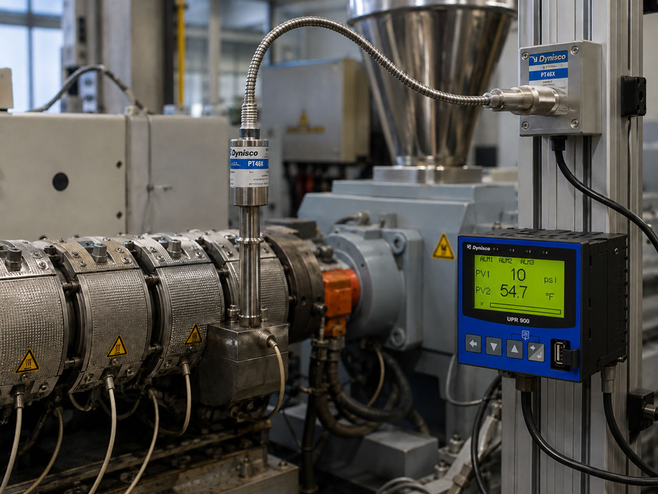
The extruder is heated up and the melt pressure sensor initially indicates 0 bar while the machine is stationary. Half an hour later, the display suddenly shows 8 bar even though no material is being conveyed yet. Is the sensor damaged or is this simply a temperature-related zero shift?
This type of behaviour occurs comparatively often with melt pressure sensors during start-up. Between the cold condition and stable process temperature, the diaphragm, stem, pressure transmission system, installation point and electronics undergo thermal changes. As a result, the output signal can shift even though the actual process pressure has not changed accordingly.
Performing a zero adjustment immediately after switching on is therefore often too early. The decisive factor is that the sensor has reached a stable operating temperature and that there is actually no process pressure acting on the diaphragm.
Melt pressure sensors for extrusion, injection moulding and polymer processing can be found under Dynisco Melt Pressure Sensors. Further sensors, transmitters, indicators and accessories are grouped under Dynisco Products.
Table of Contents
- Why does temperature change the zero point?
- What happens inside a melt pressure sensor?
- How long does a melt pressure sensor need to warm up?
- Why must the sensor really be pressure-free when zeroing?
- Correctly setting the zero point
- Why repeated zeroing can be problematic
- Considering installation stress and mounting torque
- Distinguishing between diaphragm, stem and electronics temperature
- What does the shunt test indicate?
- Avoiding cold starts and mechanical damage
- Thermal drift or damaged sensor?
- Systematic troubleshooting
- Practical example on an extruder
- Typical errors during zero adjustment and commissioning
- What should be documented?
- Which Dynisco solutions are suitable?
- Conclusion
- Frequently asked questions
Why does temperature change the zero point?
In plastics processing, a melt pressure sensor is often screwed directly into the extruder, screen changer, melt pump or mould.
At these points, temperatures of several hundred degrees Celsius can occur at the process diaphragm, while the actual measuring electronics are located in a considerably cooler area.
During heating, there is therefore no uniform temperature condition.
For example, the following components heat up one after another:
- the extruder barrel,
- then the sensor mounting point,
- the process diaphragm,
- the rigid sensor stem,
- the internal pressure transmission system,
- the flexible capillary,
- and finally, to some extent, the sensor housing or electronics.
These thermal changes can cause a shift in the electrical zero signal.
Dynisco refers to this effect in the technical data of various sensors as:
Zero Shift due to Temperature Change
The magnitude of this effect depends on the model and should therefore always be assessed using the data sheet of the specific sensor being used.
There is no single universal limit value for all Dynisco melt pressure sensors.
What happens inside a melt pressure sensor?
Many conventional melt pressure sensors use a sealed, liquid-filled pressure transmission system.
The process pressure first acts on a thin flush-mounted diaphragm.
The pressure is then transmitted via the internal fill system or a capillary to the actual measuring element.
There, the mechanical load is converted into an electrical signal, for example by means of a strain-gauge measuring bridge.
A typical design can therefore be simplified as follows:
Melt → process diaphragm → fill system → measuring diaphragm or strain gauge → electrical output signal
As the temperature rises, the materials involved change slightly.
Among other things, the following may change:
- dimensions of the metal components,
- mechanical preload,
- properties of the pressure transmission system,
- zero signal of the measuring bridge,
- properties of the electronics.
These changes are reduced as far as possible by design measures and temperature compensation, but depending on the sensor type they cannot be eliminated completely.
How long does a melt pressure sensor need to warm up?
For zero adjustment, a fixed period of time is not the decisive factor. What matters is a stable thermal condition.
A general rule such as:
“The sensor can always be zeroed after 10 minutes”
is therefore not appropriate.
The required time depends, among other things, on:
- process temperature,
- sensor design,
- stem length,
- flexible capillary,
- installation position,
- extruder mass,
- heating rate,
- ambient temperature.
For corresponding sensors, Dynisco recommends waiting before zero adjustment until a stable operating temperature has been reached at the pressure sensor.
In practice, this can be recognised by the following:
- the machine heating zones have reached their setpoints,
- the required thermal soak time has elapsed,
- the sensor zero value is no longer continuously drifting,
- no relevant temperature changes are taking place at the installation point.
For recurring machines, the actual required warm-up phase can be documented based on operating experience.
Why must the sensor really be pressure-free when zeroing?
Zero adjustment means that the currently applied output value is accepted as the zero point.
This is only correct if the sensor is actually exposed to:
0 bar process pressure or the pressure-free reference condition defined for the application
.
This is not always self-evident, especially during heating.
A machine may still contain, for example:
- trapped material,
- thermally expanding melt,
- solidified plastic,
- pressure between closed components,
- residual pressure downstream of a screen changer,
- hydrostatic or process-related pressure components.
If an actual residual pressure of, for example, 12 bar is stored as the zero point, the sensor will subsequently indicate all actual process pressures offset by approximately this amount.
The device has then not been temperature-compensated but zeroed to an incorrect reference condition.
Correctly setting the zero point
A suitable procedure for zero adjustment is:
- Install the sensor correctly: Observe the specified bore geometry and mounting torque.
- Switch on the electrical measuring chain: Put the sensor, indicator, PLC or measuring amplifier into operation.
- Heat up the system: Bring the process to the intended operating temperature.
- Wait for thermal soaking: Do not zero immediately after the heating system first reaches its setpoint.
- Ensure pressure-free condition: Verify that there is actually no process pressure acting on the diaphragm.
- Observe the zero value: Check whether the value is still drifting significantly.
- Perform zero adjustment: Zero only after a stable thermal condition has been reached.
- Observe the zero value again: The value should then remain stable close to zero.
- Start the process: Monitor the pressure increase for plausibility.
Depending on the Dynisco version, zero adjustment can be carried out, for example, using:
- a zero potentiometer,
- an external measuring amplifier,
- an indicator or controller,
- a remote-zero contact,
- digital parameterisation.
The exact procedure depends on the sensor model used.
Why repeated zeroing can be problematic
If the zero point continues to drift during heating, there is often a temptation to zero the sensor repeatedly.
However, this can conceal the actual cause.
Example:
| Time | Temperature Condition | Reading Before Zero Adjustment |
|---|---|---|
| 08:00 | cold machine | 0 bar |
| 08:20 | heating phase | +5 bar |
| 08:40 | thermal condition still changing | +9 bar |
| 09:00 | thermally stable | +10 bar |
If the sensor is zeroed at 08:20, it may shift by several bar again by 09:00.
This can make the sensor appear unstable even though it was simply zeroed too early.
It is better to observe the development of the zero signal during heating first and perform the final zero adjustment only after thermal stabilisation.
If the sensor must be repeatedly zeroed under unchanged operating conditions, however, the cause should be investigated.
Considering installation stress and mounting torque
A zero shift does not necessarily have to be caused exclusively by temperature.
The mechanical installation can also influence the output signal.
Dynisco identifies the following influences, among others:
- mounting torque,
- installation position,
- side loading,
- incorrect mounting bore.
A strong zero shift immediately when the sensor is screwed in is particularly noticeable.
Possible causes include:
- non-concentric mounting bore,
- incorrect bore depth,
- hardened plastic residue,
- damaged sealing surface,
- excessive tightening torque,
- cross-threading.
Zero adjustment must not simply be used to conceal an incorrect mechanical installation.
If the zero value is already unusually shifted when the sensor is screwed in, the mounting point should be checked first.
Distinguishing between diaphragm, stem and electronics temperature
When evaluating temperature drift, different temperature zones of the sensor must be distinguished.
Process diaphragm
It is in direct contact with the plastic melt and reaches approximately the process temperature.
Rigid stem
The stem forms the thermal transition from the hot measuring point towards the sensor or electronics housing.
Flexible capillary
On corresponding designs, it provides additional thermal and mechanical separation between the process connection and the measuring element.
Electronics or strain-gauge housing
This has its own permissible temperature range, which can be considerably lower than the maximum permissible temperature at the process diaphragm.
Therefore, for example:
process temperature up to 400 °C
does not mean that the electronics housing may also be exposed to 400 °C.
Incorrect installation with the electronics housing positioned directly against a very hot machine can therefore cause additional drift or exceed the permissible electronics temperature.
What does the shunt test indicate?
Many conventional Dynisco melt pressure sensors have an internal shunt calibration function.
For numerous models, the so-called R-Cal signal corresponds to:
80 percent of the full-scale output signal
No actual hydraulic or melt pressure is generated when the function is activated.
Instead, the electrical measuring bridge is deliberately influenced so that a defined output signal is generated.
The shunt test can therefore be used, among other things, to check:
- sensor connection,
- measuring bridge,
- cable,
- measuring amplifier,
- indicator or PLC scaling.
Example:
A sensor has a measuring range of 0 to 500 bar and an R-Cal of 80 percent.
With a correctly configured measuring chain, the activated shunt should simulate approximately:
400 bar corresponding to 80 percent of the measuring range
.
However, the shunt test does not replace a pressure calibration.
It does not apply a real known pressure to the process diaphragm or pressure transmission system.
As a result, mechanical changes to the process diaphragm, for example, cannot be fully assessed.
A correct shunt value therefore does not automatically prove that the sensor is still within its complete accuracy specification under real pressure.
In addition, the test conditions specified by the manufacturer must be observed. For certain Dynisco series, shunt calibration is explicitly described for pressure-free conditions and at room temperature, whereas the actual zero adjustment is performed at stable operating temperature.
Avoiding cold starts and mechanical damage
A significantly incorrect zero value after heating can also be the result of previous mechanical damage.
Cold starts are particularly critical.
If the extruder is started before the polymer at the sensor tip has melted sufficiently, very high local mechanical forces can act on the thin process diaphragm.
Dynisco therefore recommends allowing sufficient time for the material to melt completely before starting.
Cold starts can damage both:
- the extruder,
- and the process diaphragm of the pressure sensor.
When removing the sensor, the material at the sensor tip must also be sufficiently soft or molten.
A sensor should not be forcibly unscrewed from solidified polymer.
Thermal drift or damaged sensor?
The decisive question is often:
Can the observed zero shift still be explained by thermal effects, or is there a defect?
| Observation | Possible Interpretation |
|---|---|
| Zero value changes mainly during heating and then stabilises | Temperature-related zero shift likely |
| Zero value is similar after each comparable heating cycle | Reproducible thermal effect likely |
| Strong zero jump immediately during installation | Check mounting bore, torque or mechanical loading |
| Zero value continues to drift even at stable temperature | Investigate sensor, electronics or installation more closely |
| Sensor reacts only weakly to actual pressure increase | Mechanical defect or damaged diaphragm possible |
| Shunt test is correct but actual pressure measurement is implausible | Mechanical or process-side fault remains possible |
| Zero point changes permanently and significantly after a cold start | Check for diaphragm damage or overload |
| Zero value depends strongly on tightening torque | Check mounting bore and mechanical loading |
The decisive factor is therefore not a single zero value but its behaviour over temperature, time and several operating cycles.
Systematic troubleshooting
- Identify the sensor type: Document the model, measuring range and output signal.
- Check the history: Was there a cold start, overpressure, removal or mechanical work?
- Check the installation: Inspect bore, thread, sealing surface and mounting torque.
- Record the cold zero value: Do not correct it immediately.
- Heat up the system in a controlled manner: Observe the zero signal during the temperature rise.
- Wait for thermal stabilisation: Do not use a fixed universal time specification.
- Ensure pressure-free condition: Exclude residual process pressure.
- Document the hot zero value: Determine the difference from the cold condition.
- Perform zero adjustment: Only in a stable, pressure-free operating condition.
- Perform the shunt test: In accordance with the specifications for the particular sensor model.
- Observe the process pressure: Check the response to pressure increase and pressure reduction.
- Check the zero point after the process: Verify that the sensor returns reproducibly.
- Perform a reference check if abnormalities are found: Test the sensor using a suitable pressure source or in a calibration laboratory.
Practical example on an extruder
An extruder is equipped with a Dynisco melt pressure sensor with a measuring range of 0 to 500 bar.
When the cold system is switched on, the controller indicates:
0 bar
After approximately 20 minutes of heating, the display shows:
+6 bar
The operator resets the value to zero.
Another 30 minutes later, despite the screw still being stationary, the system again indicates:
+4 bar
Initially, a defective sensor is suspected.
During a subsequent investigation, the sensor is not zeroed at any point during the entire heating process.
| Condition | Reading |
|---|---|
| cold extruder | 0 bar |
| heating phase | +5 to +8 bar |
| close to operating temperature | +9 bar |
| after complete thermal stabilisation | +9.5 bar stable |
The process is then checked to ensure that it is genuinely pressure-free.
Only now is the sensor zeroed once.
After production starts, the pressure rises plausibly. After the later pressure reduction, the sensor reproducibly returns close to zero.
This behaviour therefore does not indicate a suddenly defective sensor but rather a temperature-related zero shift that had previously been corrected too early during the heating phase.
For future start-ups, the following procedure is defined:
- wait for the complete heating and thermal soak phase,
- verify pressure-free condition,
- check the zero value,
- only then perform the zero adjustment.
This makes commissioning reproducible and eliminates unnecessary repeated zeroing.
Typical errors during zero adjustment and commissioning
| Error | Possible Consequence | Suitable Corrective Action |
|---|---|---|
| Sensor zeroed immediately after switching on | Zero point shifts during further heating | Wait for thermal stabilisation |
| Sensor zeroed as soon as the heater first reaches its setpoint | Stem and sensor may not yet be fully heat-soaked | Allow sufficient thermal soak time |
| Residual pressure accepted as zero | All subsequent process values contain an offset | Ensure actual pressure-free condition |
| Sensor repeatedly zeroed during heating | Thermal drift is concealed | Observe and document the zero value first |
| Strong zero shift during installation ignored | Mechanical installation error remains unresolved | Check mounting bore and torque |
| Shunt test interpreted as a complete pressure calibration | Mechanical sensor faults may be overlooked | Use the shunt only as an electrical functional check |
| Cold start of the extruder | Mechanical damage to the process diaphragm possible | Allow the material to melt completely |
| Electronics housing mounted too hot | Additional drift or permissible temperature exceeded | Check thermal installation conditions |
| Every zero-point deviation immediately interpreted as sensor failure | Unnecessary sensor replacement | Investigate temperature dependency and reproducibility |
| Permanent drift accepted as a normal temperature effect | Actual defect remains undetected | Check stability under constant conditions |
What should be documented?
For recurring problems, a simple start-up log is very helpful.
At least the following should be documented:
- sensor type,
- serial number,
- measuring range,
- output signal,
- installation position,
- process temperature,
- temperature of the relevant heating zone,
- time of switch-on,
- time at which the setpoint temperature is reached,
- zero value in the cold condition,
- zero value during the heating phase,
- zero value in the thermally stable condition,
- time of zero adjustment,
- confirmation of pressure-free condition,
- shunt value if used,
- zero value after production.
This makes it possible to determine after several machine starts whether the zero shift is reproducible or whether it is increasing over time.
An increasing or no longer reproducible offset is considerably more informative than looking at a single measured value.
Which Dynisco solutions are suitable?
Dynisco melt pressure sensors
Under Dynisco Melt Pressure Sensors, various melt pressure sensors are available for extrusion, injection moulding and polymer processing.
Depending on the series, the following are available, among other options:
- mV/V outputs,
- 4 to 20 mA,
- 0 to 10 V,
- integrated temperature measurement,
- different stem and capillary lengths,
- different pressure ranges.
Dynisco PT46X4 Series
The PT46X4 series is designed for melt pressure measurements with an industrial 4 to 20 mA output.
The series offers, among other things:
- adjustable zero and span,
- local zero adjustment,
- remote-zero function on corresponding versions,
- internal 80 percent shunt calibration,
- versions for high process temperatures.
This allows the zero point to be adjusted to the specific application after thermal stabilisation.
Dynisco MDA4X2 Series
The MDA4X2 series uses a sealed, liquid-filled pressure transmission system and is designed for process and melt pressure measurements at high temperatures.
The flexible connection between the stem and housing provides thermal and mechanical separation of the measuring element from the hot process area.
Depending on the model, different accuracy classes, pressure ranges and process connections are available.
Dynisco SPX-T
For applications in which temperature-related zero-point changes are particularly critical, the Dynisco SPX-T series may be of interest.
These intelligent pressure transmitters feature temperature compensation based on an additional temperature measurement as well as DynaLarity for compensating or linearising process-related offset effects.
This can significantly reduce temperature-related drift compared with conventional versions without corresponding compensation.
The series is particularly intended for demanding process applications and, depending on the version, offers 4 to 20 mA and HART communication, among other options.
Indicators and controllers
In addition to the sensor, the complete measuring chain also includes the indicator, measuring amplifier or PLC input.
During troubleshooting, it must therefore always be checked whether the observed offset actually originates in the sensor or is already caused by:
- incorrect input scaling,
- zero point of the amplifier,
- wiring,
- supply voltage,
- analogue input of the controller.
ICS Schneider Messtechnik provides support in selecting Dynisco melt pressure sensors, transmitters, indicators and controllers as well as in assessing and testing existing melt pressure measuring points.
Conclusion
A zero-point shift during heating is not automatically an indication of a defective melt pressure sensor.
Temperature changes at the process diaphragm, stem, pressure transmission system and electronics can alter the output signal. This effect is particularly visible during machine start-up.
The critical mistake is often zeroing the sensor too early.
Correct zero adjustment is performed only when the sensor has reached a stable operating temperature in its final installed position and there is genuinely no process pressure acting on the diaphragm.
Repeated re-zeroing during the heating phase should be avoided. It is better to observe the zero value first and document its development.
Installation stress must also be considered. A strong zero jump during installation can indicate an incorrect mounting bore, unsuitable torque or lateral mechanical loading.
The internal shunt test is useful for checking the electrical measuring chain but does not replace a real pressure calibration and cannot reliably rule out mechanical damage to the process diaphragm.
If the sensor continues to drift even after complete thermal stabilisation, does not return reproducibly to zero after pressure reduction or no longer responds plausibly to process pressure, the measuring point should be investigated more closely or the sensor should be tested.
Frequently asked questions about zero drift in melt pressure sensors
Why does my Dynisco sensor suddenly indicate pressure after heating?
Temperature changes can shift the zero point of the sensor. During heating in particular, the thermal condition of the diaphragm, stem, pressure transmission system and electronics changes.
Should I zero the sensor while it is cold?
For production operation, the decisive zero adjustment should be carried out after installation at stable operating temperature and under genuinely pressure-free conditions.
How long should I wait before zeroing?
There is no universal time for all sensors and machines. The decisive factor is that the process is thermally stable and the zero value is no longer continuously drifting.
Can I zero immediately after the heater reaches its setpoint?
Not necessarily. The heating controller reaching its setpoint does not automatically mean that the extruder, sensor mounting point and complete sensor stem are already thermally stable.
Why must the machine be pressure-free during zero adjustment?
Because any actual pressure present would otherwise be stored as the new zero point. All subsequent measured values would then be shifted accordingly.
What does Zero Shift mean?
Zero Shift describes a change in the output signal even though the actual pressure remains at zero. In melt pressure sensors, this effect can be caused by temperature changes and mechanical influences, among other factors.
What is the 80 percent shunt test?
With many Dynisco sensors, an electrical signal is simulated internally that corresponds to approximately 80 percent of the measuring range full scale. This allows a large part of the electrical measuring chain to be checked.
Can the shunt test tell me whether the diaphragm is damaged?
Not reliably. The shunt test does not apply any actual pressure to the process diaphragm. A correct shunt signal therefore does not completely rule out mechanical damage on the pressure-exposed side of the sensor.
Why does the zero point shift when the sensor is screwed in?
A small change can result from the installation condition. An unusually large zero jump, however, can indicate excessive torque, an incorrect mounting bore or lateral mechanical loading.
Can a cold start damage the sensor?
Yes. If the plastic at the sensor tip has not melted sufficiently, very high mechanical forces can act on the thin process diaphragm.
When should the sensor be replaced or tested?
If the zero point continues to drift significantly despite stable temperature, the sensor does not return reproducibly after pressure reduction, reacts unusually strongly to installation influences or no longer measures the actual pressure profile plausibly, a more detailed test should be carried out.
Can temperature-related drift be reduced by design?
Yes. In addition to selecting a suitable sensor design and ensuring correct thermal installation, intelligent transmitters such as the Dynisco SPX-T series are available with additional temperature compensation for particularly demanding applications.