


A Pt100 normally measures 80 °C. Suddenly, the PLC input value rises to the upper end of the measuring range and the system interprets this as 200 °C. In reality, however, the process has not become hotter – one of the sensor wires has been interrupted.
This is exactly the kind of situation that modern temperature transmitters are designed to prevent by providing clear fault-current signalling.
Instead of transmitting a sensor break as a valid temperature, the transmitter deliberately sets its 4-to-20-mA output outside the normal measuring range. Depending on the parameterisation and the device, this is done either as a low fault current, known as Downscale, or as a high fault current, known as Upscale.
For this diagnostic function to work properly, however, not only the temperature transmitter and sensor must be configured correctly. The PLC, control system, alarm limits, substitute-value strategy and commissioning test must all follow the same logic.
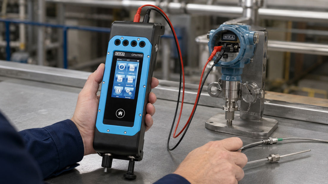
Temperature sensors and probes can be found under Temperature Sensors and Temperature Probes. Suitable instruments for simulating and testing sensor signals and 4-to-20-mA current loops are grouped under Process Calibrators and Electrical Calibrators.
Table of Contents
- What happens when a sensor breaks?
- Why is 4 to 20 mA alone not sufficient for diagnostics?
- What does NAMUR NE 43 mean?
- Should Upscale or Downscale be selected?
- Correctly detecting a sensor break with Pt100
- Wire break with a thermocouple
- What happens in the event of a sensor short circuit?
- Correctly programming PLC limits
- Separating substitute value and bad-quality status
- Planning alarms and interlocks
- Using additional diagnostics via HART
- Actually testing sensor break detection during commissioning
- Practical example from a temperature control loop
- Typical parameterisation errors
- What should be documented?
- Which devices are suitable?
- Conclusion
- Frequently asked questions
What happens when a sensor breaks?
A temperature transmitter receives its input signal, for example, from:
- Pt100,
- Pt1000,
- Ni resistance sensors,
- thermocouples,
- mV sensors.
The transmitter converts this sensor signal into a standardised output signal, frequently:
4 to 20 mA
With a configured measuring range of 0 to 200 °C, the following could apply, for example:
- 0 °C = 4 mA,
- 100 °C = 12 mA,
- 200 °C = 20 mA.
If a sensor wire is interrupted, however, there is no longer a valid temperature signal.
Without diagnostics, the evaluation electronics could calculate an implausible extreme value.
Modern temperature transmitters therefore detect such a fault and output a defined fault current instead of a normal measured value.
Why is 4 to 20 mA alone not sufficient for diagnostics?
An important point is the distinction between:
- a valid measured value,
- overrange or underrange,
- an actual fault condition.
20 mA does not automatically mean that a fault is present.
With a normal 4-to-20-mA signal, 20 mA initially corresponds to the configured upper range value.
A value slightly above 20 mA can also still indicate a valid overrange condition.
Likewise, a current slightly below 4 mA does not necessarily mean that a sensor break has occurred.
There must therefore be sufficient separation between the measuring range and the clearly defined fault range.
What does NAMUR NE 43 mean?
NAMUR NE 43 defines a commonly used system for the signal ranges of analogue 4-to-20-mA transmitters.
A typical division is as follows:
| Current Signal | Interpretation |
|---|---|
| below the lower fault range | fault or device/sensor malfunction |
| approx. 3.8 to 4.0 mA | permissible underrange or lower measuring range |
| 4.0 to 20.0 mA | normal measuring range |
| 20.0 to approx. 20.5 mA | permissible overrange |
| above the upper fault range | fault or device/sensor malfunction |
Important reference values are:
- lower output limit approximately 3.8 mA,
- upper output limit approximately 20.5 mA,
- Downscale fault typically no more than approximately 3.6 mA,
- Upscale fault typically at least approximately 21 mA.
The actual fault current that is output depends on the transmitter used and its parameterisation.
A device can, for example, be configured to:
3.5 mA Downscale
or:
21.5 mA Upscale
.
For the PLC, therefore, the decisive factor is not an arbitrary theoretical value but the actual configured fault response of the transmitter being used.
Should Upscale or Downscale be selected?
When a sensor fault is detected, the temperature transmitter can generally react in two directions.
Downscale
The output current is reduced below the normal measuring range.
For example:
3.5 mA
The PLC recognises this as an invalid measured value.
Upscale
The output current is increased above the normal measuring range.
For example:
21.5 mA
This value is also clearly outside the normal measurement signal range.
Which direction is appropriate depends on the system.
The decisive question is not whether Upscale is generally better than Downscale, but:
Which response results in a clearly recognisable and safe condition in the specific process?
For an overtemperature monitoring application, for example, a high fault current can be advantageous because a wire break is then not treated as an extremely low temperature.
In other applications, Downscale may be more suitable.
The selection should therefore be coordinated with the PLC and safety logic.
Correctly detecting a sensor break with Pt100
A Pt100 changes its electrical resistance with temperature.
If a wire breaks, the electrical resistance of the affected current path increases sharply or the circuit is interrupted completely.
A suitable temperature transmitter detects this condition and sets the output to the configured fault current.
The diagnostic behaviour also depends on the connection method:
- 2-wire,
- 3-wire,
- 4-wire.
2-wire Pt100
The sensor and the two connecting wires form a simple current path.
A complete wire break can be detected relatively clearly.
However, the lead resistance also contributes to the temperature measurement.
3-wire Pt100
The 3-wire method allows compensation of the lead resistance under certain conditions.
If an individual wire fails, the diagnostic response depends on the transmitter and its input circuitry.
4-wire Pt100
With the 4-wire method, current and voltage leads are routed separately.
This allows the influence of lead resistance to be almost completely eliminated from the measurement.
Here too, the sensor-break detection of the transmitter being used must be activated appropriately.
During commissioning, therefore, not only the sensor itself but also each individual connection wire should be checked for the correct diagnostic response where relevant to the application.
Wire break with a thermocouple
A thermocouple generates a small temperature-dependent thermoelectric voltage.
If one wire is interrupted, there is no longer a valid closed thermocouple circuit at the transmitter input.
Modern transmitters can detect this condition using integrated wire-break monitoring.
This diagnostic function is particularly important because open thermocouple wires can be sensitive to:
- electromagnetic interference,
- potential coupling,
- moisture,
- high-resistance connections
.
Without functioning sensor-break detection, apparently plausible but invalid temperature values may result.
With thermocouples, it should also be checked whether:
- the correct thermocouple type is configured,
- the correct extension or compensating cable is used,
- the polarity is correct,
- cold-junction compensation is working correctly.
What happens in the event of a sensor short circuit?
Not every sensor fault is a wire break.
With resistance thermometers, for example, a short circuit can occur between individual wires.
The measured resistance then drops sharply.
Without diagnostics, this could result in an apparently very low temperature.
Depending on the sensor type and device functionality, a suitable transmitter can also detect this condition as a fault.
It is therefore important to distinguish in the device configuration between:
- sensor break,
- sensor short circuit,
- measuring range underrange,
- measuring range overrange.
Not every temperature transmitter provides the same diagnostic functions for every connected sensor type.
The specific data sheet and device parameterisation are therefore decisive.
Correctly programming PLC limits
Even the best sensor-break detection in the transmitter is ineffective if the PLC continues to interpret every current value as a valid temperature.
A common programming error is, for example:
4 mA = 0 °C
20 mA = 200 °C
and all values outside this range are simply limited to 0 or 200 °C.
A fault current of 21.5 mA could then simply be displayed as:
200 °C
.
The information “sensor fault” is lost.
A separate signal evaluation is preferable.
For example:
| Input Current | PLC Evaluation |
|---|---|
| ≤ 3.6 mA | Downscale fault |
| 3.8 to 20.5 mA | measurement signal or defined overrange/underrange |
| ≥ 21.0 mA | Upscale fault |
The actual limits must match the configuration of the transmitter being used.
In addition, a short hysteresis or suitable time-based plausibility check may be useful if electrical interference at the analogue input module would otherwise generate unnecessary fault messages.
However, such a delay must not result in a safety-relevant sensor fault being concealed for an impermissibly long time.
Separating substitute value and bad-quality status
Many PLC and control systems use a substitute value when an input is invalid.
Examples include:
- holding the last valid value,
- using a fixed substitute value,
- using a second redundant sensor,
- bringing the process into a safe state.
Important:
A substitute value must not be treated as if it were a valid measured value.
The control system should therefore maintain at least two separate pieces of information:
- temperature value,
- quality status or diagnostic status.
Example:
Temperature = 80 °C
Status = invalid or sensor fault
This allows the visualisation to continue showing a substitute value while at the same time clearly indicating that no valid real measurement is available.
Planning alarms and interlocks
A sensor break should not appear merely as a small diagnostic message in the background.
The required response depends on the importance of the measuring point.
Possible responses include:
- warning message,
- common fault,
- alarm,
- interlocking of a heating function,
- switching to a redundant sensor,
- controlled shutdown of the system.
For safety-relevant applications, this response must be derived from the corresponding risk or safety assessment.
In particular, a sensor fault must not disappear simply because the operator acknowledges the alarm while the measuring point remains invalid.
Depending on the application, the diagnostic logic can therefore be designed so that it is only cleared after:
- a valid sensor signal has been restored,
- a new plausibility check has been performed,
- and, where necessary, a deliberate reset has been carried out.
Using additional diagnostics via HART
With a HART-capable temperature transmitter, the analogue 4-to-20-mA signal is supplemented by digital communication.
This allows additional information to be transmitted or read out in addition to the current value.
Depending on the device, this can include:
- sensor break,
- sensor short circuit,
- measuring range violation,
- device fault,
- sensor status,
- diagnostic data.
This is particularly useful because the analogue fault signal initially only indicates:
The measured value is invalid.
The digital diagnostics can additionally provide information about why the measured value is invalid.
For a robust system, however, basic fault detection should not depend exclusively on HART if the normal PLC input is being evaluated as a conventional 4-to-20-mA signal.
Actually testing sensor break detection during commissioning
A configured diagnostic function should not only be checked on a laptop.
The complete signal path should be tested in practice.
A suitable commissioning test includes, for example:
- Simulate a normal value: Apply a valid temperature value.
- Check the 4-mA point: Verify the lower range value.
- Check the 20-mA point: Verify the upper range value.
- Simulate a sensor break: Deliberately interrupt the sensor wire.
- Measure the fault current: Check whether the expected Upscale or Downscale value is output.
- Check PLC diagnostics: The signal must be recognised as invalid.
- Check the alarm: Verify the expected alarm or interlock.
- Reconnect the sensor: Observe the return to valid operation.
- Test a short circuit: Where supported by the sensor and transmitter type, check the corresponding diagnostic response.
The actual test of the PLC limits is particularly important.
Simply checking whether the transmitter outputs 21.5 mA is not sufficient if the PLC subsequently still processes this current as a valid temperature value.
Testing with a process calibrator
Depending on its functionality, a suitable process calibrator can:
- simulate Pt100,
- simulate thermocouples,
- generate mV signals,
- measure 4 to 20 mA,
- simulate 4 to 20 mA,
- provide loop power.
This allows the measuring chain to be tested step by step:
Sensor or simulation → temperature transmitter → current loop → PLC → visualisation and alarm system
This step-by-step procedure makes it easier to distinguish between sensor faults, transmitter faults, wiring faults and incorrect PLC scaling.
Practical example from a temperature control loop
A Pt100 monitors the temperature of a heated process vessel.
The temperature transmitter is configured as follows:
- measuring range: 0 to 200 °C,
- output: 4 to 20 mA,
- sensor break: Upscale,
- fault current: 21.5 mA.
The PLC initially scales the analogue input linearly from 4 to 20 mA to 0 to 200 °C.
During testing, one Pt100 wire is disconnected.
The transmitter responds correctly and outputs:
21.5 mA
.
However, the PLC software limits all values above 20 mA to the upper range value.
The visualisation therefore only displays:
200 °C
instead of:
Sensor break
.
The hardware therefore works correctly, but the diagnostic information is lost in the PLC.
The signal evaluation is therefore modified.
| Signal | Response |
|---|---|
| valid measuring range | scale temperature normally |
| upper fault current | measured value invalid, sensor-break alarm |
| lower fault current | measured value invalid, measuring-loop fault alarm |
In addition, heating is disabled when the temperature value is invalid.
The operator now no longer sees an apparently valid maximum value, but clearly sees:
Temperature measurement fault
.
After reconnecting the Pt100, the valid measured value is accepted again.
The complete fault response from the sensor through to the control system has therefore been verified.
Typical parameterisation errors
| Error | Possible Consequence | Suitable Corrective Action |
|---|---|---|
| Sensor-break detection not activated | Invalid sensor condition may appear as a temperature value | Configure the transmitter diagnostic function |
| 20 mA already interpreted as a fault | Upper range value causes a false alarm | Separate measuring range and fault range |
| 21.5 mA limited to maximum temperature | Sensor break is displayed as a valid maximum value | Evaluate the fault range before scaling |
| 3.5 mA interpreted as normal low temperature | Downscale fault remains undetected | Monitor the lower fault range separately |
| Transmitter configured for Upscale, PLC programmed only for Downscale | Sensor break is not detected | Match transmitter and PLC configuration |
| Substitute value used without fault status | Operator does not recognise the invalid measurement | Keep value and quality status separate |
| Only sensor break tested, not short circuit | Second fault condition remains undetected | Fully test the device diagnostic functions |
| Sensor break simulated only in software | Wiring and actual input stage are not tested | Physically interrupt the measuring circuit during commissioning |
| Alarm can be acknowledged although the fault is still present | Fault may disappear visually | Use condition-dependent alarm and interlock logic |
| HART diagnostics available but not used | Cause of the fault remains unclear | Use digital diagnostics as additional information |
What should be documented?
For every important temperature measuring point, at least the following data should be known:
- measuring point designation,
- sensor type,
- Pt100 connection method or thermocouple type,
- transmitter type,
- measuring range,
- 4-mA value,
- 20-mA value,
- configured sensor-break detection,
- Upscale or Downscale,
- specific fault current,
- short-circuit diagnostics where available,
- PLC lower limit,
- PLC upper limit,
- substitute-value strategy,
- alarm response,
- interlock function,
- result of the commissioning test.
This information should match the actual device configuration.
Especially when replacing a temperature transmitter at a later date, it must be checked whether the replacement device uses the same fault-current direction and the same diagnostic values.
Which devices are suitable?
Temperature sensors and temperature probes
Under Temperature Sensors and Temperature Probes, you will find various sensors for industrial temperature measuring points.
Depending on the application, these include:
- Pt100,
- Pt1000,
- thermocouples,
- screw-in temperature probes,
- insertion probes,
- probes with connection heads,
- versions with integrated temperature transmitters.
Configurable temperature transmitters
For demanding measuring points, programmable temperature transmitters are useful in which, among other things, the following can be configured:
- sensor type,
- measuring range,
- connection method,
- 4-to-20-mA scaling,
- sensor-break response,
- Upscale or Downscale,
- damping,
- HART communication depending on the device.
One example is a universal HART temperature transmitter such as the WIKA T32, which can process various resistance thermometers and thermocouples and signal sensor faults accordingly.
Process calibrators
Under Process Calibrators and Electrical Calibrators, devices are available for testing complete measuring chains.
Depending on their functionality, they can be used to:
- simulate Pt100,
- simulate thermocouples,
- generate mV,
- measure current loops,
- generate 4-to-20-mA signals,
- provide loop power
.
This allows not only the temperature transmitter itself to be tested, but the complete measuring chain through to the PLC input.
ICS Schneider Messtechnik provides support in selecting temperature sensors, temperature transmitters and process calibrators as well as in designing complete 4-to-20-mA temperature measuring points.
Conclusion
A sensor break must never simply be processed as a valid extreme value in an automated system.
The temperature transmitter should clearly detect the sensor fault and deliberately set its output outside the normal 4-to-20-mA measuring range.
NAMUR NE 43 provides a clear separation between measurement signal, overrange region and fault signal.
The correct PLC evaluation is then decisive.
An Upscale value of, for example, 21.5 mA must not simply be limited to 100 percent or to the upper range value. Likewise, a Downscale value of, for example, 3.5 mA must not be interpreted as an especially low temperature.
Upscale and Downscale must match the respective process and safety strategy.
In addition, an invalid measured value should always be associated with a clear quality status. Any substitute value used must not conceal the actual sensor fault.
With HART transmitters, additional diagnostic information can help distinguish between sensor break, short circuit, range violation and device fault.
The most important test is ultimately carried out during commissioning: physically interrupt the sensor wire, measure the fault current, observe the PLC response and check the alarm or interlock.
Only when this complete chain works correctly is it ensured that a sensor break cannot become an apparently valid temperature value.
Frequently asked questions about sensor break and fault current
What happens when a Pt100 sensor wire breaks?
The resistance path is interrupted. A suitable temperature transmitter detects this condition and outputs a defined fault current.
What does Upscale mean?
With Upscale, the transmitter sets the output above the normal measuring range when a fault is detected, for example to 21.5 mA.
What does Downscale mean?
With Downscale, the output current is reduced below the normal measuring range when a fault occurs, for example to 3.5 mA.
Is 20 mA already a fault signal?
No. With conventional 4-to-20-mA scaling, 20 mA normally corresponds to the upper range value.
Why is 3.6 mA frequently used as a fault threshold?
This ensures that the fault range is clearly below the normal or permissible lower output range. Depending on the device, the actual configured fault current may, for example, be 3.5 mA.
Why is 21 mA frequently used as the upper fault threshold?
This ensures that a fault is clearly above the normal measuring and overrange region. Many transmitters use a specific fault current of, for example, 21.5 mA.
Should I configure sensor break as Upscale or Downscale?
This depends on the process and safety logic. The selected direction must be used consistently by the transmitter, PLC and alarm strategy.
Can a thermocouple wire break be detected?
Yes, provided that the temperature transmitter being used supports appropriate thermocouple wire-break monitoring and that this function is configured correctly.
Can a temperature transmitter also detect a short circuit?
Many devices provide additional short-circuit diagnostics, particularly for resistance sensors. However, the available function depends on the transmitter and sensor type.
Can I scale the fault current directly in the PLC?
The fault range should be evaluated before or separately from the normal temperature scaling. Otherwise, for example, 21.5 mA could incorrectly appear as the maximum valid temperature.
What is the benefit of HART in the event of a sensor break?
The analogue fault signal indicates that the measured value is invalid. Depending on the transmitter, HART can provide additional diagnostic information about the specific cause.
How do I correctly test sensor-break detection?
During commissioning, the sensor circuit should be deliberately interrupted. The fault current, PLC status, visualisation, alarm and, where applicable, interlock should then be checked.