


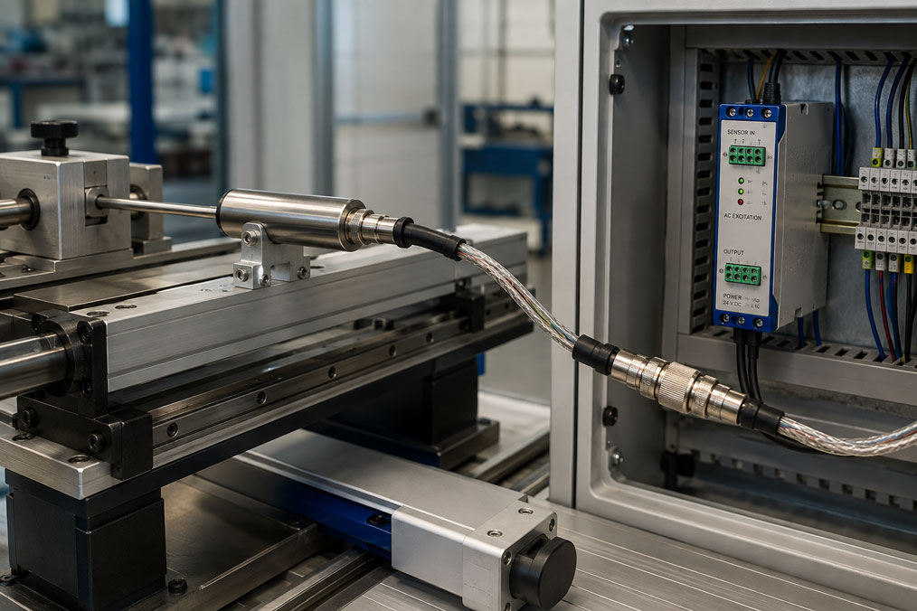
An inductive displacement sensor works perfectly on a test bench. After a machine modification, however, the sensor has to be installed farther away from the control cabinet. The connecting cable is extended by 10 or 20 metres – and afterwards the zero point is no longer correct, the sensitivity has changed or the signal becomes noticeably more unstable than before.
With a displacement sensor that already has integrated electronics and a standardised output signal, extending the cable is often comparatively straightforward. The situation is different with a conventional LVDT or inductive half-bridge displacement sensor with external signal conditioning electronics. In this case, the cable between the sensor and signal conditioner is electrically part of the measuring system. Its capacitance, conductor arrangement, shielding and excitation frequency can therefore influence the measurement.
An extension should therefore not simply be regarded as a mechanical cable modification. What matters is the complete measuring chain consisting of sensor, cable, connectors, signal conditioner and downstream evaluation electronics.
Suitable sensors can be found under Displacement transducers / displacement sensors / probes. Further solutions for displacement, force and motion measurement are grouped under Displacement, force and motion sensors.
Table of Contents
- Why is the cable part of the measuring system?
- How does an LVDT work?
- What distinguishes an inductive half-bridge?
- How does cable capacitance influence the signal?
- What role does the excitation frequency play?
- Why is the signal conditioner so important?
- How to correctly extend four-, five- and six-wire connections
- Shielding and EMC with long cables
- Why can the zero point shift?
- Typical errors after extending the cable
- Recommended procedure for extending a sensor cable
- Why should the system be calibrated afterwards?
- Practical example from a test bench
- Which products and solutions are suitable?
- Conclusion
- Frequently asked questions
Why is the cable part of the measuring system?
With sensors that provide a conditioned output such as 0–10 V or 4–20 mA, the essential signal electronics are already integrated into the sensor or located directly next to it. A comparatively low-impedance signal designed for transmission is then transferred between the sensor and the control system.
With a passive inductive displacement sensor, however, the signal conditioner is located outside the sensor. The actual AC or bridge signals are present between the sensor and the electronics. An additional cable therefore changes the electrical characteristics of this connection.
The following factors are particularly relevant:
- capacitance between individual conductors,
- capacitance between conductors and shield,
- cable resistance,
- unequal conductor lengths and contact resistances,
- connectors and terminal points,
- electromagnetic interference from the environment, and
- the excitation frequency used by the signal conditioner.
The sensor, cable and input stage of the signal conditioner therefore form one complete electrical system. This is precisely why an arbitrary extension cable is not automatically equivalent to the originally specified sensor cable.
How does an LVDT work?
An LVDT – Linear Variable Differential Transformer – is an inductive displacement sensor with one primary winding and two secondary windings. The primary winding is supplied with an AC voltage. A movable ferromagnetic core changes the magnetic coupling to the secondary windings depending on its position.
In the centre position, the two secondary signals are ideally equal in magnitude. Their difference approaches the electrical zero point. When the core is moved away from this position, one secondary voltage increases while the other decreases.
The evaluation does not only take the amplitude into account. The phase relationship with respect to the excitation is also used to determine the direction of movement relative to the zero point.
The external signal conditioner therefore performs several functions: it generates the appropriate AC excitation for the sensor, detects the differential signal, demodulates it and then converts it, for example, into a usable DC voltage, current or digital signal.
What distinguishes an inductive half-bridge?
In addition to conventional LVDT systems, inductive displacement sensors based on the half-bridge principle are also available. Here too, a movable core changes the electrical properties of coils. However, the evaluation circuit differs from that of a full LVDT.
One example from the ICS product range is the ISM205. It operates according to the inductive half-bridge principle and provides an analogue sensor signal.
For practical applications, the following is therefore essential: the wiring of an LVDT must not simply be transferred to a half-bridge transducer. Even sensors that look very similar externally can have different winding configurations and different requirements for the signal conditioner.
Before extending any cable, the sensor type, wiring diagram and compatible evaluation electronics must therefore be clearly identified.
How does cable capacitance influence the signal?
Every cable has electrical capacitance. With a short sensor cable, its influence is often negligible. As the cable length increases, however, the total cable capacitance increases approximately proportionally.
In simplified form:
Ctotal ≈ C’ × L
Here, C’ is the capacitance of the cable per metre and L is the cable length.
If, for example, a cable has a relevant capacitance of 100 pF/m, a 20 m cable already results in approximately 2 nF. Since a passive LVDT or half-bridge sensor is operated with AC excitation, this capacitance does not act only as a static value.
The capacitive reactance can be described in simplified form as:
XC = 1 / (2 × π × f × C)
As the frequency or cable capacitance increases, this reactance decreases. The cable can therefore increasingly load the AC signal and, together with the sensor windings and the input stage of the signal conditioner, influence both amplitude and phase.
The practical consequence does not necessarily have to be a complete failure. Much more frequently, smaller changes occur that can already be relevant in precision displacement measurement:
- changed sensitivity,
- zero-point shift,
- changed gain or span,
- greater phase errors,
- poorer linearity, or
- increased susceptibility to interference.
A general statement such as “LVDT cables may always be 20 m long” is therefore not meaningful. The permissible length depends on the specific sensor, signal conditioner, cable type and selected excitation frequency.
What role does the excitation frequency play?
A conventional LVDT requires an AC voltage at a frequency suitable for the sensor. Depending on the sensor and signal conditioner, different frequencies in the kHz range may be specified.
The frequency influences both the inductive properties of the sensor windings and the effect of the cable capacitance. A frequency that works optimally with a short cable therefore does not necessarily produce the same result with every possible cable length.
If the signal conditioner has an adjustable excitation frequency, it should nevertheless not be changed experimentally until the result “looks approximately correct” again. The sensor and electronics must be treated as a matched system.
After changing the excitation frequency or cable length, it must be checked whether the zero point, sensitivity and linearity of the complete measuring chain still meet the requirements.
Why is the signal conditioner so important?
With a passive inductive displacement sensor, the signal conditioner is not merely an amplifier connected downstream of the sensor. It is part of the actual measuring principle.
Depending on the system, it provides functions such as:
- AC excitation of the displacement sensor,
- evaluation of the differential voltage,
- phase-sensitive demodulation,
- zero-point adjustment,
- gain or span adjustment,
- filtering, and
- conversion to a standardised output signal.
For this reason, not every signal conditioner can be combined with every inductive displacement sensor. The input circuit, excitation frequency, excitation voltage or current and sensor topology must be compatible.
Replacement becomes particularly critical if the sensor and signal conditioner were originally adjusted together. Some measuring systems are intentionally used as a matched sensor/electronics combination. A different signal conditioner can then cause significant measurement deviations despite apparently compatible connections.
If a long distance has to be bridged, it is therefore often advantageous to keep the sensitive connection between the passive sensor and signal conditioner as short as possible and to transmit only the already conditioned output signal over the long distance – provided that the sensor design, ambient conditions and system architecture allow this.
How to correctly extend four-, five- and six-wire connections
Different connection variants exist for LVDT systems. Depending on the design, winding connections may be internally joined or brought out individually. Signal conditioners are therefore available, depending on the version, for four-, five- or six-wire sensor connections.
With a six-wire LVDT, the primary and secondary windings can be brought out largely separately. Other designs already have internally connected winding terminals and therefore require fewer conductors.
For cable extension, this means:
- The original conductor assignment must be preserved exactly.
- Related signal conductors should also be routed as corresponding pairs in the extension cable.
- The conductors should have the same length wherever possible and comparable electrical characteristics.
- The cable shield must not be used as a substitute for a signal conductor.
- Connectors and intermediate terminals must provide reproducible, low-resistance contacts.
It is particularly dangerous to assume that identical conductor colours on two different sensors automatically have the same function. Only the documented wiring of the specific sensor and signal conditioner is authoritative.
Shielding and EMC with long cables
As the cable length increases, not only does the capacitance increase. The cable also presents a larger effective area for electromagnetic interference.
Potential sources of interference include cables running in parallel from frequency converters, servo drives, motors, contactors or high-power solenoid valves.
For a robust installation, suitable shielded cables with appropriately arranged or twisted conductor pairs should therefore be used. Sensor cables and power cables should be routed separately wherever possible. Long parallel runs directly adjacent to motor or inverter cables should be avoided.
The specific shield connection depends on the signal conditioner, system grounding and EMC concept. A general rule such as “always connect the shield at one end only” is just as problematic as always connecting it at both ends. In industrial installations, shielding and equipotential bonding must be considered together and implemented in accordance with the manufacturer’s specifications.
It is also important not to unnecessarily interrupt the shield within an extension point or continue it via long unshielded connection wires. Especially at terminal points, the otherwise good shielding effectiveness of the cable can otherwise be lost.
Why can the zero point shift?
The electrical zero point of an LVDT occurs where the two secondary signals largely cancel each other out. In practice, a small residual signal normally remains at the zero point.
If the cable is modified, additional capacitances, different contact resistances or asymmetrical cable routing can influence the two signal paths slightly differently. The signal conditioner may therefore derive a different electrical zero point.
A zero-point shift after a cable modification does not therefore automatically mean that the sensor has moved mechanically.
Conversely, a new offset should not simply be eliminated using the zero adjustment potentiometer without first checking the cause. A zero adjustment corrects only the offset. Any simultaneous change in sensitivity or linearity remains unaffected.
After a cable modification, at least two points should therefore be checked: the zero point and a known displacement. For demanding measurements, a multi-point check is advisable.
Typical errors after extending the cable
| Observed error | Possible cause | Recommended check |
|---|---|---|
| Constant zero-point offset | Asymmetrical extension, contact resistance or changed electrical loading | Check the wiring and then adjust the zero point in a controlled manner |
| Measured value at the end point too low or too high | Changed sensitivity caused by cable and signal conditioner | Check the span using a known mechanical displacement |
| Zero point correct, but intermediate values incorrect | Possible linearity or phase error | Perform a multi-point check |
| Measured value fluctuates when the motor is running | EMC interference | Check cable routing, shielding and equipotential bonding |
| Error occurs only after using a new cable type | Different cable capacitance or conductor arrangement | Compare cable data with the original cable |
| Signal direction is reversed | Incorrect winding or conductor assignment | Check the sensor wiring diagram |
| Sensor behaves significantly differently with another signal conditioner | Sensor and signal conditioner incompatible or adjusted differently | Check approval and electrical characteristics of the combination |
Recommended procedure for extending a sensor cable
A systematic approach prevents several faults from having to be investigated simultaneously after the modification.
- Clearly identify the sensor: Document the type, measuring principle, connection assignment and existing signal conditioner.
- Check the initial condition: Before the modification, record the zero point and at least one known displacement point.
- Determine the original cable: Document the number of conductors, shielding, conductor cross-section and – if available – capacitance data.
- Check the permissible cable length: Observe the manufacturer’s specifications for the sensor and signal conditioner.
- Select a suitable extension cable: Consider electrical symmetry, low and defined capacitance and appropriate shielding.
- Continue conductor pairs correctly: Do not interchange winding connections and do not use the shield as a signal return conductor.
- Route the cable in accordance with EMC requirements: Maintain distance from power cables and frequency converters and implement the specified shield connection.
- Check the zero point: Bring the sensor into the defined mechanical reference position.
- Check the span: Move to one or, preferably, several known displacement positions.
- Document the result: Record the new cable length and any signal conditioner or zero-point adjustments in the measuring equipment documentation.
Why should the system be calibrated afterwards?
With a passive inductive sensor, extending the cable changes one component of the measuring chain. Even if the measured value appears plausible afterwards, this does not prove that the original measurement accuracy has been maintained.
For simple machine monitoring applications, a comparison at several known positions may be sufficient. For test benches, quality measurements or measuring chains subject to calibration requirements, however, the complete chain consisting of sensor, extended cable and signal conditioner should be checked or calibrated.
A meaningful multi-point check can include, for example, the zero point, several intermediate positions and the upper or lower region of the actual measuring range used.
The assessment should not focus exclusively on the end points. In theory, a cable modification can be compensated in such a way that the zero point and end value are correct again while the intermediate values still show larger deviations.
If the signal conditioner is readjusted after changing the cable, this setting also becomes part of the measuring chain and should be documented.
Practical example from a test bench
On a test bench, an inductive displacement sensor is used to measure the movement of a valve. The sensor and signal conditioner were originally only around two metres apart.
After a modification, the control cabinet is moved to the opposite side of the system. The sensor cable therefore has to be extended by approximately 15 m.
After the modification, the sensor initially shows a small offset in its mechanical reference position. The zero point is then readjusted on the signal conditioner. During the subsequent check of the end point, however, it becomes apparent that the indicated displacement also differs from the previous setting.
The cause is therefore not limited to the zero point. The extended sensor cable has changed the electrical measuring chain.
The installation is then checked systematically. A suitable shielded cable with defined conductor pairs is used for the extension, the winding connections are assigned continuously in accordance with the sensor wiring diagram and the cable route is separated from the motor cables of the test bench.
The complete measuring chain is then checked using mechanically defined reference positions. Only afterwards are the zero point and span of the signal conditioner finally adjusted.
The important conclusion: if only the zero point had been corrected, the test bench would have appeared to be correct again in the starting position, while the displacement measurement over the remaining measuring range would still have been incorrect.
Which products and solutions are suitable?
ISM205 – inductive displacement sensor based on the half-bridge principle
The ISM205 is an example of a passive inductive displacement sensor based on the half-bridge principle. Sensors of this type clearly demonstrate why the sensor cable and external electronics must be considered together.
When extending the cable, compatibility with the intended evaluation electronics and the cable used must therefore be taken into account.
ISM21 – compact displacement sensor with external electronics
The ISM21 is an inductive displacement sensor for measuring ranges up to 20 mm and is designed for operation with external electronics. The housing diameter is 10 mm; depending on the version, a degree of protection up to IP68 is available.
With this type of system architecture in particular, it should be checked before significantly extending the sensor cable which cable length and cable type are intended for the electronics being used.
ISM26 – inductive displacement sensor for larger measuring ranges
For larger measuring ranges, the ISM26 is available. It covers measuring ranges up to 200 mm, has a housing diameter of 12 mm and is likewise intended for use with external electronics.
This makes the series suitable, for example, for machine and test-bench applications in which the sensor and control cabinet may be physically separated.
Sensors with integrated electronics as an alternative
If long cable runs are unavoidable by design, it may also be worth considering whether a displacement sensor with integrated electronics is more suitable for the application. With the ISM40, the electronics are already integrated into the sensor.
This means that the passive inductive sensor signal itself is no longer present on the longer cable. Nevertheless, the specifications for maximum cable length, output load, power supply and EMC of the specific version must still be observed.
Further sensors and designs can be found under Displacement transducers / displacement sensors / probes.
ICS Schneider Messtechnik supports you in selecting the appropriate inductive displacement sensor, measuring range, evaluation electronics and signal transmission method, as well as in the technical assessment of existing measuring chains following machine modifications.
Conclusion
Extending the connecting cable of a passive LVDT or inductive half-bridge displacement sensor is not comparable to simply extending an ordinary power cable.
Additional cable capacitance, conductor resistance, connection points and possible EMC interference change the electrical conditions between the sensor and signal conditioner. Particularly with AC-excited sensors, both amplitude and phase can therefore be affected.
A zero point that has shifted after the extension should therefore not automatically be corrected simply by readjusting it. Sensitivity, span and, for higher accuracy requirements, linearity must also be checked.
The complete measuring chain is what matters: sensor, cable, connectors, signal conditioner and evaluation electronics. If a long distance is required, it may be technically advantageous to keep the sensitive sensor cable short and place the signal conditioner closer to the transducer, or to use a sensor with integrated electronics.
After every significant modification to the sensor cable, the complete measuring chain should be checked under the actual installation conditions and, in quality-critical applications, calibrated accordingly.
Frequently asked questions about extending cables for inductive displacement sensors
Can I simply extend an LVDT cable?
Not in every case. With a passive LVDT, the cable is part of the electrical connection between the sensor windings and the signal conditioner. Cable type, capacitance, conductor assignment and maximum permissible length must therefore be compatible with the sensor and signal conditioner.
Why does the zero point change after extending the cable?
Additional or asymmetrical cable capacitances and contact resistances can influence the signal paths differently. This can shift the electrical zero point determined by the signal conditioner.
Can I simply correct the error using the zero adjustment?
Only if it has been demonstrated that the error is exclusively an offset. After modifying the cable, at least the sensitivity or span should also be checked. For precision measurements, a multi-point check is required.
Why does the excitation frequency matter with an LVDT?
The sensor operates with AC excitation. Both the sensor windings and the cable capacitance have frequency-dependent characteristics. The excitation frequency must therefore be suitable for the combination of sensor and signal conditioner.
Is the thickest possible cable automatically better?
No. A larger conductor cross-section reduces ohmic resistance, but says nothing about the cable capacitance, conductor arrangement or shielding that are important for an LVDT. An electrically suitable cable type is what matters.
Should the signal conditioner be located closer to the sensor or inside the control cabinet?
For long distances, positioning it closer to the passive sensor can be advantageous because this keeps the sensitive AC sensor cable shorter. Whether this is possible and appropriate depends, however, on temperature, degree of protection, power supply and the design of the signal conditioner.
Can I use a displacement sensor with an integrated amplifier instead of a passive sensor?
This can be useful for long transmission distances. In that case, an already conditioned signal is transmitted over the long cable. However, the sensor must still be suitable for the application with regard to measuring range, dynamics, ambient conditions, output signal and accuracy.
Does the system have to be recalibrated after extending the cable?
For a precise or quality-critical measurement, the complete measuring chain should at least be checked after a significant modification to the sensor cable. If the cable was part of the original calibration or if signal conditioner settings were changed, recalibration is particularly advisable.