


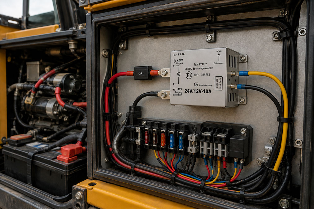
A construction machine has a 24 V electrical system and its sensor electronics require a stable 12 V supply. At first glance, the selection seems simple: 24 V input, 12 V output, sufficient current – done. Nevertheless, the electronics may occasionally fail during engine start or become damaged after several months due to disturbances in the vehicle electrical system.
The reason is often that a vehicle electrical system is not an ideal DC voltage source. During engine starting, the voltage can drop significantly. Switching inductive loads can generate short voltage spikes. Under certain conditions, a load-dump event can produce a considerably higher overvoltage. In addition, reverse polarity, ground potential shifts, EMC interference and thermal loads must be taken into account.
A DC-DC converter for mobile applications must therefore not only match the nominal voltage. What matters is the actual voltage range and transient loads it must withstand at the installation location, as well as the output quality required by the connected electronics.
Suitable DC voltage converters can be found under DC-DC Converters. Further components for supplying measuring, control and monitoring systems are grouped under Power Supply.
Table of Contents
- Why are vehicle electrical systems problematic?
- What happens during a load dump?
- Correctly considering voltage drops during engine starting
- Why is the input voltage range alone not sufficient?
- Reverse polarity and negative transients
- When is galvanic isolation useful?
- Correctly planning the grounding concept and voltage drops
- Considering output power and inrush current
- EMC and cable routing
- Efficiency, temperature and cooling
- Degree of protection and installation location
- Correctly assigning vehicle standards
- Systematically selecting a DC-DC converter
- Practical example of a mobile 24 V machine
- Suitable DC-DC converters
- Conclusion
- Frequently asked questions
Why are vehicle electrical systems problematic?
The designations 12 V, 24 V or 48 V initially describe only the nominal voltage of a vehicle electrical system. The actual voltage present can deviate considerably from this value.
With the engine running, the battery is charged by an alternator or DC charging system. As a result, the normal operating voltage is already higher than the battery voltage alone. During engine starting, however, the starter draws a very high current and can cause a significant short-term voltage drop.
Mobile machines also contain numerous inductive loads: solenoid valves, relays, motors, pumps, fans and contactors. Switching these loads on and off generates transient disturbances that can affect other devices through the shared electrical system.
The key question is therefore not:
“Is the machine a 24 V vehicle?”
but rather:
“What minimum, maximum and transient input voltage actually reaches the DC-DC converter?”
What happens during a load dump?
A particularly critical event is the so-called load dump. In simplified terms, it occurs when an alternator is supplying current and the battery or another significant load is suddenly disconnected from the vehicle electrical system.
The battery normally acts as a large electrical buffer. If this buffering effect suddenly disappears, the system voltage can rise significantly. The connected electronics are then exposed to an overvoltage that can be considerably higher than the normal charging voltage.
The magnitude and duration of such an event depend on the vehicle electrical system and the existing protective circuitry. Modern vehicle architectures may already limit such events centrally. Nevertheless, a DC-DC converter must not be considered load-dump resistant solely because of its nominal voltage.
An input specification of, for example, 18 … 28 V DC normally describes a permissible continuous operating range. Short-term overvoltage withstand capability must be specified separately or verified by an appropriate test.
Correctly considering voltage drops during engine starting
The opposite problem occurs during engine starting. The starter requires a very high current for a short period of time. At the same time, low battery temperature, long connection cables or an aged battery can further increase the voltage drop.
The question for the DC-DC converter is then whether it can maintain its output voltage during this dip.
If the input voltage falls below the permissible undervoltage limit, the converter may switch off or reduce its output voltage. This is not automatically a defect. However, it becomes critical if the connected control system restarts uncontrollably as a result.
In a mobile measuring system, even a short restart can cause a data logger to lose measured values. In a machine control system, communication modules, displays or sensor supplies may reboot and only become available again several seconds later.
It must therefore be decided in advance whether the load must ride through the starting process without interruption or whether a defined restart is acceptable.
Why is the input voltage range alone not sufficient?
When selecting a converter, only the input voltage range specified in the data sheet is often considered. This value is important, but it is not sufficient on its own.
| Specification | What it describes | What must also be checked |
|---|---|---|
| Nominal input 24 V DC | Intended vehicle electrical system | Actual operating range of the machine |
| Input range e.g. 18 … 28 V DC | Continuous operating range | Cranking below and transients above this range |
| Overvoltage protection | Internal protective function | Permissible amplitude, duration and energy |
| E1 approval | Vehicle-related approval of the version | Whether the required electrical test profiles of the specific application are covered |
| Output 12 V / 10 A | Nominal output power | Inrush current and dynamic load behaviour |
| IP degree of protection | Protection against contact, foreign objects and water | Temperature, vibration and actual installation location |
This distinction prevents a common incorrect selection: a converter can operate perfectly during normal operation and still be unsuitable for the actual starting or fault conditions of the vehicle.
Reverse polarity and negative transients
In addition to positive overvoltage, incorrect polarity must also be considered. Reverse polarity can occur, for example, during maintenance work, battery replacement or jump-starting.
Whether a converter can tolerate reverse polarity permanently or only briefly must be specified in its technical data. A fuse alone does not provide complete reverse-polarity protection.
Negative voltage transients can also occur in the vehicle electrical system. The input protection circuitry must therefore be considered as a complete system. Depending on the application, this can include internal or external measures such as reverse-polarity protection, transient voltage suppression, filtering and suitable fuses.
The components required depend on the protective circuitry already integrated into the DC-DC converter. Additional external protection should therefore not be dimensioned according to a universal standard circuit.
When is galvanic isolation useful?
With a galvanically isolated DC-DC converter, there is no direct conductive DC connection between input and output. This allows a separate reference potential to be established on the output side.
This can offer significant advantages with long cable runs, sensitive measurement technology, differing ground potentials or interference-sensitive communication systems.
However, galvanic isolation is not fundamentally required for every mobile machine. Many compact vehicle converters intentionally use a common negative potential. This reduces complexity, size and cost.
The important point is that this characteristic is already known during the planning stage. If a non-isolated converter is used, input negative and output negative are electrically connected depending on the design. Ground potential shifts in the vehicle electrical system can therefore be transferred directly to the supplied electronics.
Galvanic isolation should therefore be selected deliberately and should not be regarded as a general synonym for a “better” DC-DC converter.
Correctly planning the grounding concept and voltage drops
In mobile machines, high currents often flow through shared ground cables and chassis connections. Even small contact resistances can cause measurable voltage drops.
A sensitive pressure sensor, for example, may be supplied from a stabilised 12 V converter while its signal ground is routed back to the control unit via another cable path. If different potentials exist between these ground points, measurement errors can occur even though the converter itself provides a perfectly stable output voltage.
The grounding concept is therefore just as much a part of the power supply design as the selection of the converter itself.
High load currents from starters, pumps or solenoid valves should not unnecessarily share the same small ground conductors as sensitive measurement signals. Power supply and signal routing must be designed according to the machine architecture.
Considering output power and inrush current
A load with a nameplate rating of 80 W does not necessarily require only an 80 W converter.
Controllers, displays, radio devices or computers often contain input capacitors. When switched on, these can cause a significantly higher short-term current. Motor-driven loads and solenoid valves also have dynamic load characteristics.
The DC-DC converter must therefore be able to handle both the continuous load and the switch-on process. Otherwise, the overload protection may trip even though the load would be within the permissible power range after start-up.
A certain amount of power reserve is therefore advisable. However, this reserve must not simply be created by using oversized fuses. Cables, connectors and protective devices must be suitable for the maximum possible current of the entire supply circuit.
EMC and cable routing
A DC-DC converter is itself a switched electronic system. At the same time, it operates in an environment containing strong electrical interference sources.
Cable routing is therefore crucial. Long unshielded supply loops increase the effective area for electromagnetic coupling. Power cables to motors, inverters or solenoid valves should not be routed directly in parallel with sensitive sensor cables unless necessary.
Input and output filters also only work as intended if grounding, cable lengths and the connection concept are correct.
If problems occur, an increasingly large filter should therefore not automatically be retrofitted. First, it should be clarified whether the interference is conducted, radiated or coupled through a shared ground.
Efficiency, temperature and cooling
A DC-DC converter with 90 % efficiency still generates more than 20 W of power loss at 200 W output power. This heat must be dissipated.
This is particularly relevant in mobile machines. A converter may be installed in an enclosed electrical cabinet directly next to hydraulic units or engine components. At the same time, the enclosure can be additionally heated by direct sunlight.
The maximum permissible output power must therefore not be considered independently of the ambient temperature. If the device has a derating curve, it must be taken into account during design.
With fan-cooled devices, another factor must be considered: dust and contamination can reduce cooling performance over time. In very dusty construction machinery, a convection-cooled, enclosed solution may therefore be the more robust alternative despite its larger size.
Degree of protection and installation location
A dry electronics cabinet in a driver’s cab has different requirements from an outdoor installation on the vehicle frame.
With direct machine mounting, moisture, splash water, dust, salt, oil and strong vibration may occur. A high IP degree of protection can therefore be an important selection criterion.
However, it does not indicate whether the converter can also withstand the required electrical transients or temperature conditions.
Degree of protection, electrical withstand capability and mechanical robustness are separate characteristics and must all match the application.
Correctly assigning vehicle standards
For road vehicles, defined test procedures exist for electrical loads and transient disturbances. These include ISO 7637-2 for conducted transients in 12 V and 24 V vehicles and ISO 16750-2 for electrical loads on vehicle components.
However, these standards must not be applied indiscriminately to every mobile application.
A construction machine may have additional manufacturer-specific requirements. Rail vehicles, in turn, are subject to separate railway standards. Even with 48 V systems, it must be checked which specification actually applies to the vehicle or installation location.
Tender specifications should therefore preferably not state only “DC-DC converter for 24 V vehicle”. It is more useful to define the input voltage range, transient withstand capability, EMC requirements, temperature range, degree of protection and, where applicable, the required approval.
Systematically selecting a DC-DC converter
| Design Criterion | Question to Be Clarified | Typical Mistake |
|---|---|---|
| Vehicle electrical system | 12, 24 or 48 V, and what is the actual voltage range? | Considering only the nominal voltage |
| Starting process | What minimum voltage must be bridged? | Failing to consider cranking |
| Overvoltage | Which transient or load-dump profiles apply? | Interpreting the normal input range as transient withstand capability |
| Output | What continuous and peak power does the load require? | Providing no reserve for inrush current |
| Ground | May input and output be galvanically connected? | Discovering the common negative only during commissioning |
| Environment | Temperature, dust, water and vibration? | Comparing electrical data only |
| Standards | Which vehicle or OEM requirements actually apply? | Equating E1 approval with complete transient qualification |
With this approach, the converter is not selected on the basis of a single data-sheet value but as part of the complete vehicle electrical system.
Practical example of a mobile 24 V machine
A mobile working machine has a 24 V electrical system. A data logger, radio router and several sensors are to be retrofitted and supplied together from a stabilised 12 V source.
The normal power consumption is approximately 70 W. The initially selected DC-DC converter provides 12 V and has sufficient nominal power. During normal machine operation, the system works without problems.
However, when the engine is cold, the data logger occasionally restarts.
A measurement directly at the converter input shows that the vehicle electrical system voltage drops significantly for a short time during cranking. At that moment, the converter leaves its specified operating range and can no longer maintain the 12 V output voltage.
It is also found that the radio router and data logger draw a higher peak current when switched on simultaneously than expected based on their normal power consumption.
The solution is therefore not simply to install a larger fuse. Instead, the power supply is redesigned: permissible input voltage range, behaviour during starting, required power reserve and the grounding concept are considered together.
In the next step, it is also checked which vehicle transient requirements the converter must meet for the specific machine.
This turns what appears to be a simple 24 V to 12 V voltage conversion into a power supply that is genuinely suitable for the vehicle electrical system.
Suitable DC-DC converters
2218.2 – 24 V to 12 V for automotive applications
For conventional 24 V vehicle electrical systems, the type 2218.2 DC-DC converter is one suitable option. The corresponding version converts 24 V DC to 12 V DC and supplies up to 10 A or 120 W.
The device is offered with E1 approval for automotive use, making it a specific solution for vehicle and mobile applications. Input and output are not galvanically isolated in this version.
During system design, the specified input voltage range must nevertheless be compared with the actual electrical requirements of the vehicle.
2239.1 – 12 V to 24 V
If a 12 V vehicle electrical system is available and a 24 V load needs to be supplied, the type 2239.1 is available, for example.
This is also a switched DC-DC converter with E1 approval for corresponding automotive applications. The converter operates as a step-up converter and provides 24 V DC.
2239.61 – 12 V to 24 V with high output power
For significantly higher-power loads, the type 2239.61 provides an output of up to 720 W or 24 V DC at 30 A.
At these power levels, cable cross-section, fusing, cooling, voltage drop and inrush current become even more important. The converter is not galvanically isolated and uses a common negative reference.
Further versions with different input and output voltages, power ratings and enclosure designs can be found under DC-DC Converters.
ICS Schneider Messtechnik provides support in selecting input voltage, output power, vehicle version, degree of protection and required galvanic isolation for mobile measuring, control and power supply systems.
Conclusion
A DC-DC converter for a mobile machine must not be selected solely on the basis of the labels 12 V, 24 V or 48 V.
The actual vehicle electrical system contains voltage drops as well as overvoltages and fast transients. In particular, engine starting and load dump can create operating conditions far outside the normal nominal voltage range.
The continuous input voltage range of a converter therefore does not automatically indicate which short-term vehicle transients it can withstand.
Output power reserve and dynamic load behaviour are equally important. A load can require significantly more current during switch-on than during normal operation.
With sensitive measurement technology, the grounding concept must also be considered. Non-isolated converters electrically connect input and output and can therefore transfer vehicle ground potential shifts to the connected electronics.
Finally, temperature, cooling, degree of protection, EMC and the actually required vehicle or OEM standards must match the installation conditions.
The correct procedure is therefore: first define the vehicle electrical system and its fault conditions, then determine the requirements of the load and only then select the DC-DC converter.
Frequently asked questions about DC-DC converters in vehicles and mobile machines
What is a load dump?
A load dump is an overvoltage in the vehicle electrical system that can occur, in simplified terms, when the battery or a large load is suddenly disconnected while the alternator is running.
Is a DC-DC converter with an 18 … 28 V input range suitable for every 24 V vehicle?
No. This range initially describes the normal permissible input operating range. Starting voltage, transients, overvoltages and the test requirements applicable to the vehicle must also be considered.
Why does a 24 V converter fail only during engine starting?
During starting, the vehicle electrical system voltage can drop significantly due to the high starter current. If the converter’s lower input limit is exceeded, its output voltage can collapse or the device may switch off briefly.
What does galvanic isolation mean in a DC-DC converter?
The input and output have no direct conductive DC connection. This allows a reference potential to be established on the output side that is electrically isolated from the vehicle electrical system.
Do I always need a galvanically isolated vehicle converter?
No. Many vehicle applications operate without problems using a common negative potential. Galvanic isolation is particularly useful when differing potentials, sensitive measurement technology or interference problems must be taken into account.
Does E1 approval automatically mean load-dump resistance?
Not automatically. For the specific application, it must be verified which electrical and transient test requirements the device actually fulfils.
How much power reserve should a DC-DC converter have?
This depends on the load. In addition to normal continuous power, inrush current, short-term peak load, ambient temperature and any power derating at high temperatures must be considered.
Why is the grounding concept important?
High currents in the vehicle can cause voltage drops between different ground points. In sensitive measuring and sensor systems, this can result in measurement errors, communication problems or restarts.
Which standards are relevant for automotive DC-DC converters?
For road vehicles, ISO 7637-2 and ISO 16750-2 may be relevant, among others. Rail vehicles and other mobile machines may be subject to different or additional standards and manufacturer-specific requirements.