


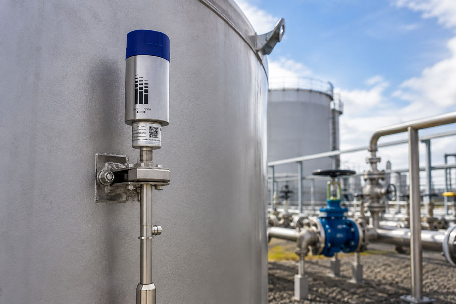
A remote tank is equipped with a new level sensor. The measured value on site is correct, wireless transmission works during commissioning and a plausible level appears on the dashboard. Nevertheless, a few weeks later, data packets are regularly missing. After several months, the battery is also discharged much faster than expected.
In another case, the wireless connection works reliably, but the operator does not receive the low-level alarm until there is practically no time left to arrange a refill.
Both examples demonstrate:
Reliable IIoT tank monitoring consists of more than just a level sensor.
The entire measurement and transmission chain must be planned as one system:
- measuring principle and sensor,
- tank geometry,
- measurement and transmission interval,
- wireless standard,
- gateway or mobile network coverage,
- position of the radio unit or antenna,
- battery power supply,
- limit values and alarm delays,
- data buffering and communication monitoring,
- maintenance and battery replacement strategy.
Especially with remote tanks, mobile containers and widely distributed supply networks, system reliability is often determined less by sensor accuracy than by the correct design of the wireless communication and alarm strategy.
Suitable solutions can be found at ICS Schneider under IIoT level monitoring. Further solutions for networking measuring points can be found under IIoT solutions.
Table of Contents
- How does wireless tank monitoring work?
- Distinguishing between sensor, radio node, gateway and cloud
- Radar, hydrostatic or float measurement?
- Non-contact radar measurement
- Hydrostatic level measurement
- Float and reed measurement
- Level height is not automatically tank volume
- LoRaWAN, LPWAN or LTE?
- Why “10 km range” is not a planning range
- Metal tanks and radio shielding
- Positioning the radio unit and antenna
- Selecting the gateway location correctly
- Separating measurement interval and transmission interval
- What determines battery life?
- Estimating battery life
- Influence of temperature on the battery
- Defining Hi, HiHi, Lo and LoLo correctly
- Hysteresis to prevent alarm chatter
- Deriving alarm limits from consumption and response time
- Rate of change for leakage and filling detection
- What happens if the wireless connection fails?
- Alarm for communication failure as well
- Why every measured value needs a timestamp
- Special considerations for mobile tanks
- Geofencing requires position data
- Wireless monitoring in hazardous areas
- Planning maintenance and battery replacement
- Typical fault patterns
- Systematic commissioning
- Practical example: remote supply tank
- Suitable ICS products for IIoT tank monitoring
- Conclusion
- FAQ
How does wireless tank monitoring work?
With conventional wired level measurement, the measured value is transmitted to a PLC or control system, for example as:
- 4…20 mA,
- 0…10 V,
- HART,
- Modbus.
For a remote tank, however, such wiring is often:
- too expensive,
- technically complex,
- impossible for mobile tanks,
- or uneconomical because of long distances.
An IIoT solution therefore supplements the actual level measurement with wireless transmission.
In simplified form, the system consists of:
Tank → level sensor → radio node → wireless network → gateway/network → server/cloud → dashboard/alarm
Each of these stages can influence the reliability of the overall system.
A highly accurate sensor is of little benefit if the radio signal cannot reliably leave the tank location.
Conversely, a perfect wireless connection is of little benefit if an unsuitable measuring principle provides an incorrect level value.
Distinguishing between sensor, radio node, gateway and cloud
Different system components are often confused during planning.
Level sensor
It determines the actual process variable:
- level height,
- distance to the liquid surface,
- hydrostatic pressure,
- float position.
Radio unit or radio node
The radio unit receives the measured value and transmits it wirelessly.
Depending on the system, it can:
- be integrated directly into the measuring instrument,
- be connected to an existing 4…20 mA sensor,
- communicate with the sensor via a digital interface.
Gateway
In a LoRaWAN or LPWAN system, the gateway provides the connection between the wireless network and the IP network.
One gateway can receive data from many geographically distributed measuring points.
Backend or cloud
This is where, for example:
- measured values are stored,
- tank volumes are calculated,
- trends are displayed,
- limit values are monitored,
- notifications are triggered.
The complete architecture should be defined before selecting the devices – not just the sensor.
Radar, hydrostatic or float measurement?
Wireless transmission does not change the basic rules of level measurement.
The measuring principle suitable for the tank and medium must be selected first.
| Measuring principle | Typical advantage | Factors to consider during design |
|---|---|---|
| Radar | Non-contact | Tank geometry, antenna position, interfering reflections and dead zone |
| Hydrostatic | Simple relationship between pressure and liquid height | Density, temperature, gas-space pressure and installation height |
| Float / Reed | Direct mechanical detection of the liquid surface | Density, float design, insertion length and process connection |
| Magnetostrictive | High-resolution float position | Float, insertion length and process conditions |
The wireless standard should only be selected once it is clear:
Which measured variable is produced by the sensor and how must it be processed further?
Non-contact radar measurement
With a radar sensor, the distance between the sensor and the surface of the medium is determined without contact.
If the tank geometry is known, the level height can be calculated from this distance.
Advantages include:
- the sensor does not have to be immersed in the medium,
- no hydrostatic dependence on density,
- low mechanical wear.
For a wireless application, however, a distinction must be made between:
- the radar measuring signal inside the tank,
- the external wireless path used for IIoT communication.
The fact that the radar sensor measures reliably inside a metal tank does not automatically mean that a LoRaWAN signal can also be transmitted reliably from a metallic installation area.
Hydrostatic level measurement
For an open tank system, the following simplified relationship applies:
p = ρ · g · h
where:
- p = hydrostatic pressure,
- ρ = density of the medium,
- g = gravitational acceleration,
- h = liquid height.
This gives:
h = p / (ρ · g)
Wireless transmission can work perfectly while the displayed level is still incorrect if an incorrect density is used for the conversion.
This is particularly relevant for:
- changing media,
- temperature-dependent density,
- oils and fuels,
- chemicals,
- mixtures with changing composition.
For closed or pressurized tanks, the gas-space pressure must also be taken into account.
Float and reed measurement
Another option is direct detection of the liquid surface using a float.
The float follows the level and magnetically transfers its position to the measuring system.
This principle is particularly useful when:
- direct mechanical level detection,
- clearly defined tank geometry,
- a robust process solution
are required.
In this case, the density of the medium must match the float design.
If the medium density is too low, the float cannot provide the required buoyancy.
The WIKA FLRU offered by ICS operates with a reed measuring chain and is specifically designed for combination with the WIKA NETRIS®3 radio unit.
Level height is not automatically tank volume
A level sensor often initially measures a height or distance.
The user, however, may require:
- liters,
- cubic meters,
- percentage of tank contents,
- remaining supply duration in days.
For a vertical cylindrical tank with a constant cross-section, the conversion is simple:
V = A · h
For other geometries, the relationship is not linear.
Examples:
- horizontal cylindrical tank,
- spherical tank,
- conical tank bottom,
- tank with several geometric sections.
A reading of:
50% level height
therefore does not necessarily mean exactly:
50% tank volume
.
For such tanks, a:
- tank characteristic curve,
- strapping table,
- or geometric volume linearization
should be used.
Alarm limits for replenishment or dry-running protection in particular should, where possible, be based on the actual available volume.
LoRaWAN, LPWAN or LTE?
Different communication methods can be used for wireless tank monitoring.
LoRaWAN / LPWAN
Low-power wide-area technologies are particularly useful for small amounts of data and long battery life.
A typical tank node does not need to transmit large amounts of data.
Usually, the following are sufficient:
- level,
- battery status,
- device status,
- timestamp,
- temperature, if required.
This makes LPWAN particularly attractive for widely distributed tank measuring points.
LTE / mobile network
Mobile communication can be useful when:
- no dedicated LoRaWAN network is available,
- public mobile network coverage at the location is sufficient,
- larger amounts of data need to be transmitted,
- a direct IP connection is required.
However, mobile communication is not automatically the better solution.
Depending on the radio modem, network conditions and transmission strategy, power consumption may be higher.
The application is decisive
| Requirement | Possible wireless strategy |
|---|---|
| Many tanks on one industrial site | A dedicated LPWAN/LoRaWAN network may be useful |
| Individual tanks distributed across a large region | Check public LPWAN or mobile network |
| Very long battery life, few measured values | LPWAN particularly attractive |
| Mobile containers | Check network coverage at the actual operating locations |
| Hazardous area | Use only appropriately approved field devices |
Why “10 km range” is not a planning range
Very large maximum ranges are often specified for wireless products.
These values must not be interpreted directly as a guaranteed radius around every gateway.
The actual wireless connection depends, among other things, on:
- terrain,
- buildings,
- steel structures,
- tank geometry,
- mounting height,
- position of transmitter and gateway,
- radio interference,
- antenna orientation.
A radio node may operate reliably over a long distance in open terrain and yet have a significantly poorer connection only a few hundred meters away behind several steel buildings.
Therefore:
Manufacturer-specified maximum range ≠ guaranteed range at the actual tank location.
Metal tanks and radio shielding
Large metal surfaces are particularly relevant for wireless tank monitoring.
A steel tank can:
- shield the radio signal,
- reflect it,
- block it in certain directions.
Particularly unfavorable positions for a radio unit include:
- inside a closed metal cabinet,
- between two large steel tanks,
- directly behind a massive tank body in the direction of the gateway,
- very low between pipes and steel structures.
During planning, the question should therefore not only be:
“How far is the tank from the gateway?”
but also:
“Which metallic obstacles are actually located in the wireless path?”
Positioning the radio unit and antenna
Even a small change in position can significantly improve or reduce radio quality.
During installation, care should be taken to ensure that the radio unit or antenna:
- is not unnecessarily shielded by the tank itself,
- is not completely enclosed by metallic components,
- is not installed directly behind large steel structures,
- remains mechanically protected,
- is installed within the permissible mounting conditions of the device.
A higher mounting position can be helpful in certain installations.
However, this must not result in:
- impermissible cable routes,
- violation of hazardous-area requirements,
- unsafe maintenance access.
The best position from a radio perspective must also be permissible from a process and mechanical perspective.
Selecting the gateway location correctly
With several tanks, the gateway location should not be selected only according to the shortest distance.
More important is achieving favorable radio coverage for all relevant measuring points.
A suitable location should ideally provide:
- a high mounting position,
- few massive obstacles,
- reliable power supply,
- reliable network connection,
- maintenance access.
In large tank farms, a central location can be more heavily shielded by:
- steel tanks,
- pipe racks,
- buildings
than a slightly more distant but higher location.
A practical radio test is therefore advisable before the final installation.
Separating measurement interval and transmission interval
One of the most important factors affecting battery life is the distinction between:
measurement interval and transmission interval.
For example, a system could:
- measure every 60 seconds,
- but transmit a wireless value only every 15 minutes.
This may be useful when short-term changes need to be detected locally but not every measured value has to be transmitted individually.
For slowly changing storage tanks, an even longer interval may be sufficient.
For a process vessel that is filled or emptied quickly, however, a 60-minute transmission interval may be far too long.
The correct question is not:
“How often can the device transmit?”
but:
“How often does the user need a new measured value in order to react in time?”
What determines battery life?
The battery life of a wireless measuring point does not depend only on the nominal capacity of the battery.
Important influencing factors include:
- measurement interval,
- transmission interval,
- sensor power consumption,
- radio transmission power,
- number of required retransmissions,
- network quality,
- temperature,
- self-discharge,
- battery aging,
- additional status or diagnostic transmissions.
A radio node that transmits once per hour can, under otherwise identical conditions, operate considerably longer than a device that transmits every minute.
Statements such as:
“up to 10 years of battery life”
must therefore always be considered in relation to the underlying operating conditions.
Estimating battery life
For an initial estimate, the average current consumption can be considered.
In simplified form:
Iavg = Isleep + Imeasurement + Iradio
The theoretical operating time can be approximated as:
t ≈ Cusable / Iavg
where:
- t = theoretical operating time,
- Cusable = actually usable battery capacity,
- Iavg = average current consumption.
Additional reserves should be taken into account for realistic system design.
The nominal battery capacity is not fully usable under every operating condition.
A sensible design should therefore not assume that the calculated battery life will end exactly at the next scheduled maintenance date.
Influence of temperature on the battery
Outdoor tanks can be exposed to large temperature fluctuations.
For example:
- -20 °C in winter,
- direct sunlight in summer,
- high surface temperatures on the tank.
The available battery performance can depend on temperature.
Temperature also influences:
- internal electronics,
- sensor power supply,
- chemical aging of the battery.
For an outdoor application, it is therefore not sufficient to check only the permissible ambient temperature of the radio device.
The planned maintenance and battery replacement strategy must also match the actual temperature profile.
Defining Hi, HiHi, Lo and LoLo correctly
Good remote monitoring requires more than one alarm.
Typical limit values are:
| Alarm | Typical meaning |
|---|---|
| Hi | High level, monitor filling process |
| HiHi | Critical high level or overfill risk |
| Lo | Low inventory, replenishment or planning required |
| LoLo | Critically low level or risk to supply or pump |
These limits should not be arbitrarily set to:
80%, 90%, 20%, 10%
.
The actual process function is decisive.
Hysteresis to prevent alarm chatter
If a tank level is exactly at an alarm limit, the measured value can repeatedly move above and below the limit due to:
- wave movement,
- measurement noise,
- temperature changes,
- minor filling and withdrawal activity.
Without hysteresis, this results in:
Alarm → no alarm → alarm → no alarm
.
This produces unnecessary notifications.
A defined reset threshold or hysteresis should therefore be provided.
Example:
- Lo alarm at 25%,
- alarm reset only above 30%.
The specific hysteresis must match the process and the stability of the measured value.
Deriving alarm limits from consumption and response time
For supply tanks, the most important value is often not the percentage level but the remaining time until a critical condition is reached.
Assume:
- remaining volume at Lo alarm: 2,000 l,
- average consumption: 400 l per day.
The theoretical reserve is therefore:
tReserve = 2,000 l / 400 l/day = 5 days
However, if the supplier requires:
- two days for scheduling,
- one additional safety day
this limit may be sufficient.
With a consumption of 1,000 l per day, however, only two days would remain.
The alarm threshold would have to be set correspondingly higher.
The correct Lo alarm therefore results from tank reserve, consumption, replenishment lead time and safety reserve – not from an arbitrary percentage.
Rate of change for leakage and filling detection
In addition to absolute limits, the rate of change can also be useful.
In simplified form:
Rate = ΔV / Δt
An unusually rapid decrease in level can indicate, for example:
- high consumption,
- unplanned withdrawal,
- leakage.
A rapid increase, on the other hand, can indicate a filling process.
For such functions, however, the following must be considered:
- measurement noise,
- transmission interval,
- tank geometry,
- known pump or process cycles.
A rate-of-change alarm should therefore not be derived from only two individual measuring points without plausibility checking.
What happens if the wireless connection fails?
One of the most important questions when designing an IIoT system is:
What happens if there is no wireless connection for several hours?
Possible system concepts include:
- transmitting only current values,
- buffering measured values locally and transmitting them later,
- processing only events or limit values locally,
- reporting communication failure separately.
Not every radio unit automatically supports all of these functions.
It should therefore already be defined during system selection:
- whether measured values may be lost during an outage,
- how long data must be stored locally,
- whether historical data should be retransmitted after the connection is restored,
- where alarm rules are executed.
For safety-critical or supply-critical tanks, a cloud connection must not be used as the sole protection layer without further assessment.
Alarm for communication failure as well
A particularly dangerous condition is:
The level may already be below the alarm threshold – but the last received measured value is several hours old.
The system should therefore monitor not only process limits but also the freshness of the data.
Example:
- regular transmission interval: 15 minutes,
- last measured value older than 45 or 60 minutes,
- trigger communication alarm.
This turns:
Level = 42%
into a much more meaningful piece of information:
Level = 42%, measured 7 minutes ago, communication OK
.
Why every measured value needs a timestamp
A measured value without time information can be dangerously misinterpreted in a wireless application.
The dashboard should therefore clearly show:
- when the value was measured,
- when it was transmitted,
- whether the measuring point is currently online.
Especially after a wireless communication interruption, an old value must not appear to represent the current tank condition.
Useful data records therefore include:
- timestamp,
- measuring-point ID,
- measured value,
- unit,
- status or quality indicator.
Special considerations for mobile tanks
With mobile tanks, not only the level but also the wireless environment may change.
A tank may be:
- on an open industrial yard today,
- between two buildings tomorrow,
- inside a warehouse later.
A wireless connection that works during commissioning therefore does not necessarily work identically at every future location.
For mobile applications, the following should be clarified:
- which operating areas must be covered,
- whether LoRaWAN/LPWAN coverage is available there,
- whether a mobile network would be more suitable,
- how communication failures are handled.
Geofencing requires position data
For mobile containers, a geofencing function is often required as well.
An alarm may, for example, be triggered when a tank:
- leaves a defined location,
- reaches a specific warehouse,
- is operated outside an approved zone.
However, position information is required for this purpose.
A LoRaWAN level measurement alone does not provide GPS or GNSS positioning.
Geofencing must therefore be planned as a separate system function.
Depending on the architecture, this may require, for example:
- GNSS,
- mobile network positioning,
- another available source of position information.
Wireless monitoring in hazardous areas
Many tank applications are located in potentially explosive atmospheres.
Examples include:
- fuels,
- solvents,
- chemicals,
- petrochemical products.
In this case, the complete field installation must be suitable for the respective hazardous area and explosion-protection requirements.
It is not sufficient to select only an intrinsically safe level sensor.
The following must also be checked:
- sensor approval,
- radio unit,
- connection between sensor and radio unit,
- cables and connectors,
- permissible installation zone,
- maintenance and battery replacement requirements.
With NETRIS®2 and NETRIS®3, ICS offers radio units designed for corresponding applications in hazardous areas.
Planning maintenance and battery replacement
“Battery-powered” does not mean “maintenance-free”.
A sensible maintenance plan takes into account:
- battery condition,
- battery age,
- radio quality,
- sensor condition,
- contamination,
- mechanical damage,
- seals and connectors,
- calibration or inspection requirements.
In particular, the battery should not only be replaced once it is completely discharged.
Instead, a defined:
- maintenance period,
- capacity alarm,
- or remaining battery value
should be used as a replacement criterion, provided the system supplies the corresponding information.
Typical fault patterns in wireless tank monitoring
| Observation | Possible cause | Recommended check |
|---|---|---|
| Sensor indicates correctly on site, but no values reach the dashboard | Wireless path, gateway or backend is malfunctioning | Check the measurement chain step by step from sensor to backend |
| Wireless communication works with the control cabinet open but fails when it is closed | Metal enclosure shields the radio signal | Check the position of the radio unit or antenna |
| Connection works only on one side of the tank | Metal tank shields the path toward the gateway | Change the position of the radio unit or gateway and check radio coverage |
| Battery is discharged much earlier than expected | Transmission interval too short, poor radio quality, retransmissions or unfavorable temperature | Check the transmission strategy and actual operating conditions |
| Level is correct but percentage value is wrong | Incorrect scaling or tank geometry | Check zero point, measuring span and volume characteristic curve |
| Hydrostatic measurement changes after changing the medium | Different density | Check density parameter |
| Alarm arrives too late for replenishment | Lo limit defined only as a percentage instead of using consumption and delivery lead time | Calculate alarm threshold from remaining volume and response time |
| Alarm is repeatedly activated and reset | No hysteresis or hysteresis too small | Define deadband or reset threshold |
| Dashboard shows a plausible 40% although the tank is now empty | Last measured value is outdated | Configure heartbeat or communication alarm |
| Data gaps after wireless communication interruption | No local buffering or retransmission provided | Check data storage and offline concept |
| Mobile tanks do not work at certain locations | Different radio coverage | Check coverage at the actual operating locations |
| Wireless level value fluctuates significantly during filling | Process movement or unsuitable averaging | Check measuring principle, measurement interval and filtering |
| Tank volume does not increase proportionally with measured level height | Non-linear tank geometry | Use a strapping table or volume linearization |
Systematic commissioning of an IIoT tank measuring point
A structured commissioning procedure prevents sensor, wireless and software faults from being confused with each other.
- Define the measurement task: Level height, volume, percentage level or remaining supply time?
- Document the medium: Density, temperature, chemical properties and hazardous-area classification if applicable.
- Record tank geometry: Height, volume, shape and relevant dead zones.
- Select measuring principle: Radar, hydrostatic, float or another suitable method.
- Define measuring range: Clearly define zero point and end point.
- Store the volume characteristic: If height and volume are not linearly related.
- Select wireless standard: LoRaWAN/LPWAN, mobile communication or existing infrastructure.
- Assess the location: Consider buildings, tanks and steel structures.
- Determine radio position: Avoid shielding by the tank and metal enclosures.
- Check gateway position: Test radio coverage for all intended measuring points.
- Define measurement interval: Adapt it to process dynamics.
- Define transmission interval: Balance response time against battery consumption.
- Check battery concept: Consider temperature and maintenance interval.
- Define alarm limits: Hi, HiHi, Lo and LoLo according to process requirements.
- Define hysteresis: Prevent alarm chatter.
- Define communication alarm: Monitor the age of the most recent measured value.
- Define offline behavior: Clarify data loss, local buffering and retransmission.
- Check sensor locally: Compare the measured value with a known level or reference.
- Perform end-to-end test: Trace the sensor value all the way to the dashboard.
- Simulate an alarm: Specifically test the limit value and notification.
- Simulate wireless interruption: Check the communication alarm.
- Document: Record sensor, radio device, measuring range, alarm limits, intervals and battery data.
Practical example: remote supply tank
At an industrial site, a remote supply tank is no longer to be checked manually every day.
The tank is located approximately 600 m from the main building.
Between the main building and the tank there are:
- two production buildings,
- a pipe rack,
- several large metal vessels.
Step 1: Define the measurement task
The following are required:
- current level,
- tank contents in percent,
- Lo alarm for replenishment,
- LoLo alarm as a critical minimum inventory,
- communication monitoring.
Step 2: Define the measurement interval
The tank contents change only slowly during normal operation.
Transmission every minute is therefore unnecessary.
For this application, a considerably slower transmission rate is selected so that sufficient data freshness and battery life are balanced appropriately.
Step 3: Check the wireless connection
An initial mounting position on the side of the tank facing away from the main building results in an unstable connection.
The radio node is then installed at a more suitable position.
This reduces shielding by the tank body.
Step 4: Check the gateway
The gateway location is not selected solely on the basis of the shortest geometric distance.
A higher position with a more favorable wireless path to the tank measuring points provides the more stable connection.
Step 5: Calculate the Lo alarm
The average consumption is:
350 l/day
Up to four days may pass between ordering and delivery.
An additional safety buffer of two days is required.
The necessary reserve is therefore:
VReserve = 350 l/day × 6 days = 2,100 l
The Lo alarm should therefore be set so that at least approximately this usable quantity remains.
A general setting of 10% would only be appropriate if these 10% actually correspond to at least the required reserve.
Step 6: Define communication alarm
In addition to the level, the freshness of the measuring point is monitored.
If no new data are received over several expected transmission intervals, a separate communication alarm is generated.
Step 7: Test failure behavior
During commissioning, the wireless connection is deliberately interrupted.
This is used to check:
- how the dashboard identifies the last measured value,
- when the communication alarm is triggered,
- how the system behaves once the connection is restored.
Result: Reliable tank monitoring is achieved not by sensor installation alone, but by the combined planning of the measuring point, radio position, transmission interval and alarm reserve.
Suitable ICS products for IIoT tank monitoring
WIKA NETRIS®1 – wirelessly integrating standard sensors into IIoT systems
The WIKA NETRIS®1 is particularly useful when a level sensor with a conventional standard signal is to be integrated into a wireless monitoring system.
The radio unit listed by ICS can process signals from connected measuring instruments, including:
- 4…20 mA,
- 0…10 V,
- Pt100 or Pt1000 in 2- or 3-wire configuration.
Depending on the version or configuration, wireless communication options include:
- LoRaWAN®,
- mioty®,
- Bluetooth®.
The wireless transmission can be battery-powered or externally supplied.
ICS specifies a transmission range of up to 10 km and a battery life of up to 10 years for the NETRIS®1.
For actual system design, however, these maximum values must be compared with the actual:
- radio coverage,
- transmission frequency,
- sensor power requirements,
- ambient temperature.
NETRIS®1 can therefore be suitable, for example, for retrofitting existing level sensors with a standard signal output.
Further information can be found under WIKA NETRIS®1 at ICS Schneider.
WIKA NETRIS®2 – two 4…20 mA inputs for hazardous-area applications
The WIKA NETRIS®2 is intended for applications in hazardous areas.
The version listed by ICS provides:
- LoRaWAN® transmission,
- battery-powered wireless transmission based on LPWAN,
- two intrinsically safe analog 4…20 mA inputs,
- transmission range of up to 10 km under appropriate conditions,
- battery life of up to 10 years under appropriate conditions.
NETRIS®2 is therefore particularly useful when an existing or suitable level transmitter with a 4…20 mA output is to be connected wirelessly and the installation is located in a hazardous area.
The two input signals may also be useful in applications where several analog measured variables need to be transmitted together.
Further information can be found under WIKA NETRIS®2 at ICS Schneider.
WIKA NETRIS®3 – LoRaWAN radio unit for compatible WIKA measuring instruments
The WIKA NETRIS®3 is also designed for applications in hazardous areas.
Unlike NETRIS®2, the radio unit receives its measurement data digitally from a compatible WIKA measuring instrument via an intrinsically safe interface.
The NETRIS®3 listed by ICS provides, among other things:
- LoRaWAN® transmission,
- battery-powered LPWAN communication,
- configurable data packets,
- IP65 ingress protection,
- connection to a compatible WIKA measuring instrument via connector,
- transmission range of up to 10 km under appropriate conditions,
- battery life of up to 10 years under appropriate conditions.
For tank monitoring, NETRIS®3 is particularly useful in combination with WIKA level measuring instruments designed for this purpose, such as the FLRU.
Further information can be found under WIKA NETRIS®3 at ICS Schneider.
WIKA FLRU – reed level transmitter for combination with NETRIS®3
The WIKA FLRU is a reed level transmitter specifically intended for combination with the WIKA NETRIS®3 radio unit.
The level is detected using a magnetic float.
The magnetic system of the float actuates a resistance measuring chain inside the guide tube. This produces a signal proportional to the level height.
The version listed by ICS provides, among other things:
- IIoT capability in combination with NETRIS®3,
- process temperatures from -80 … +200 °C,
- operating pressure from vacuum up to 80 bar,
- minimum density from 400 kg/m³,
- various process connections and materials,
- intrinsically safe Ex i version.
The density discussed in this article must be taken into account particularly when selecting the FLRU.
The float must be suitable for the medium and its density.
FLRU and NETRIS®3 therefore form a technically coordinated solution for web-based remote monitoring of liquid levels.
Further information can be found under WIKA FLRU at ICS Schneider.
Which solution is suitable for which setup?
| Application | Suitable ICS solution |
|---|---|
| Existing level sensor with 4…20 mA or 0…10 V in a non-hazardous area | Check NETRIS®1 according to the specific version |
| 4…20 mA level sensor in a hazardous area | Check NETRIS®2 according to approval and intrinsically safe design |
| WIKA level instrument with the intended digital interface in a hazardous area | NETRIS®3 |
| Float-based IIoT level measurement | WIKA FLRU + NETRIS®3 |
| Many remote tank measuring points with small amounts of data | Consider an LPWAN/LoRaWAN architecture |
| Existing analog sensor is to be retrofitted | Check output signal and hazardous-area requirements and select the appropriate NETRIS radio unit |
An overview of the solutions currently available from ICS can be found under IIoT level monitoring at ICS Schneider.
Conclusion
Reliable wireless tank monitoring does not begin with the cloud and does not end with the level sensor.
The complete measurement chain is decisive:
Tank → measuring principle → sensor → radio unit → wireless path → gateway or network → data processing → alarm.
The correct level measuring method must be selected first.
For hydrostatic measurement, for example, density is relevant; for float measurement, float design is important; and for non-contact measurement, tank geometry and the installation situation must be considered.
The wireless path must then be planned realistically.
Large metal tanks, steel buildings and pipe racks can significantly affect radio coverage. A maximum range stated in a data sheet is therefore no substitute for testing at the actual location.
Another particularly important point is the distinction between measurement interval and transmission interval. Not every locally recorded measured value necessarily needs to be transmitted immediately. A sensibly selected transmission interval can significantly improve battery life.
Alarm limits should also be derived from the process. For a supply tank, a Lo alarm is useful when, after it is triggered, enough inventory remains for:
- response time,
- ordering,
- delivery time,
- safety reserve.
In addition to the actual level, the freshness of the data should always be monitored. An old measured value must not appear to represent the current tank condition.
For existing sensors, a wireless retrofit using NETRIS®1 or NETRIS®2 may be suitable depending on the application. For a coordinated float-based IIoT level solution, the WIKA FLRU and NETRIS®3 are available.
For practical applications, the recommended sequence is therefore:
Define tank and medium → select measuring principle → correctly convert height into volume → select wireless standard → check actual radio coverage → position the radio unit appropriately → define measurement and transmission intervals → plan battery life with sufficient reserve → define Hi/HiHi/Lo/LoLo and hysteresis → monitor communication failure → define offline behavior → perform end-to-end commissioning.
FAQ: Wireless Tank Level and IIoT Monitoring
How can a tank level be monitored remotely?
A level sensor detects the tank contents or level height. A radio unit transmits the measured value, for example via LoRaWAN, another LPWAN technology or a mobile network, to a gateway or backend where it can be displayed and monitored.
Which measuring principle is suitable for a tank?
This depends on the medium, tank geometry, pressure, temperature and installation conditions. Typical methods include radar, hydrostatic measurement, float/reed measurement and magnetostrictive level measurement.
Is radar suitable for wireless tank monitoring?
In principle, yes. The level measuring method and the external wireless transmission are two separate functions. A suitable output signal from the radar sensor must be compatible with the intended radio unit.
Can a hydrostatic level sensor be connected wirelessly?
Yes, provided its output signal is compatible with a suitable radio unit. With hydrostatic level measurement, the density of the medium must also be taken into account.
Why is density important for hydrostatic level measurement?
Hydrostatic pressure is determined by p = ρ × g × h. If the density changes, the measured pressure also changes at the same liquid height.
Why is density also important for float level sensors?
The float must generate sufficient buoyancy in the medium. A float design therefore has a defined minimum or limit density.
What is LoRaWAN?
LoRaWAN is a wireless technology and network architecture for low-power transmission of small amounts of data over comparatively long distances. This makes it particularly attractive for distributed IIoT measuring points.
Is LoRaWAN suitable for tank monitoring?
Yes. Level measuring points usually generate only small amounts of data and often do not require transmission every second. They are therefore fundamentally well suited to low-power wide-area applications.
Which is better: LoRaWAN or LTE?
This depends on the infrastructure and application. LPWAN is particularly attractive for small amounts of data and long battery life. Mobile communication can be useful where public network coverage is available and no dedicated gateway is to be installed.
How far does LoRaWAN reach at a tank?
The actual range depends strongly on terrain, buildings, metal structures, mounting position and gateway location. Maximum values specified for a device should therefore not be regarded as the guaranteed range of the actual installation.
Can a metal tank shield the radio signal?
Yes. Large metal surfaces can reflect and shield radio signals. The position of the radio unit or antenna should therefore already be considered during system planning.
Can a radio unit be installed inside a metal cabinet?
A completely closed metal enclosure can significantly impair wireless transmission. The specific installation must therefore be planned according to the device requirements and the actual radio conditions.
Why does wireless communication work better on one side of the tank than on the other?
The metal tank body can shield the direct wireless path to the gateway. The position of the radio unit can therefore have a significant influence on the connection.
Where should a LoRaWAN gateway be installed?
Ideally, it should be positioned so that there are few massive obstacles between the gateway and the measuring points. A higher mounting position can be helpful. Power supply, network connection and maintenance access must also be considered.
Should I perform a radio coverage test before installation?
For critical or heavily shielded locations, practical testing of radio coverage is very useful. A pure distance calculation does not adequately take steel structures and buildings into account.
What is the difference between the measurement interval and transmission interval?
The measurement interval determines how often the sensor determines a new value. The transmission interval determines how often data are actually transmitted wirelessly.
Does every measured level have to be transmitted immediately?
Not necessarily. For slowly changing tanks, a longer transmission interval may be sufficient. However, data freshness must match the required response time of the application.
How can battery life be extended?
A suitable measurement and transmission interval, stable radio conditions and a measurement chain matched to the application can reduce energy consumption. However, the interval must not be so long that critical changes are detected too late.
Why can poor radio coverage reduce battery life?
Depending on the wireless architecture, unfavorable connection conditions can require additional communication attempts or retransmissions. Radio quality and energy planning should therefore be considered together.
How long does the battery in an IIoT radio sensor last?
This depends on the device, battery, measurement and transmission intervals, ambient temperature and radio conditions. For various NETRIS radio units, ICS specifies battery life of up to 10 years under suitable conditions.
Should I plan using the maximum specified battery life?
No. Sufficient reserve should be included in a realistic maintenance plan. Ambient temperature, actual radio conditions and the selected intervals must be taken into account.
Which alarm limits are useful for a tank?
Hi, HiHi, Lo and LoLo are commonly used. The specific values must be derived from the process, required reserve, overfill protection, pump operation and response time.
What is a Lo alarm?
A Lo alarm indicates a low level and can, for example, trigger replenishment or scheduling activities.
What is a LoLo alarm?
LoLo normally indicates a critically low condition in which, for example, supply could fail or a pump could be at risk.
Why should a Lo alarm not simply be set to 10%?
Because 10% tank contents can correspond to completely different remaining operating times depending on tank size and consumption. The limit should be derived from remaining volume, consumption, delivery lead time and safety reserve.
What is hysteresis in a level alarm?
Hysteresis defines a separate reset threshold. This prevents a measured value close to a limit from repeatedly switching the alarm on and off.
What does rate of change mean?
This evaluates not only the absolute level but also its change over time. An unusually rapid decrease can, for example, indicate high withdrawal or a possible leak.
Can wireless tank monitoring detect leaks?
An unusual change in level can be used as an indicator. Whether a leak can be identified reliably from this depends on tank operation, measurement accuracy and known withdrawals.
What happens if the wireless connection fails?
This depends on the system architecture. It should therefore be defined whether measured values are stored locally, retransmitted later or may be lost during the interruption.
What is an offline buffer?
An offline buffer stores measured values locally during a communication interruption and may retransmit them once the connection is restored. Not every device automatically supports this function.
How can I detect that a wireless measuring point has failed?
In addition to the level, the freshness of the last data packet should be monitored. If no new value is received over several expected transmission intervals, a communication alarm can be triggered.
Why is the timestamp important?
It shows when the level was actually measured. This prevents an outdated measured value from being incorrectly interpreted as the current tank condition.
What is a heartbeat for an IIoT measuring point?
A heartbeat or regular status signal confirms that the measuring point is still communicating. If it is no longer received, a communication or device fault can be detected.
Can I monitor mobile tanks using LoRaWAN?
In principle, yes, provided suitable radio coverage is available at the intended operating locations. With changing locations, this coverage requires particular attention.
Can LoRaWAN automatically locate a tank?
Not based on the level measured value alone. A suitable source of position information must be included in the system architecture for reliable geofencing or location tracking.
What is geofencing for a mobile tank?
Geofencing means using available position data to monitor whether the tank is inside or outside a defined geographical zone.
Can wireless level measurement be used in a hazardous area?
Yes, provided all components used are suitable and appropriately approved for the respective hazardous area and installation method.
Which ICS radio unit is suitable for 4…20 mA in hazardous areas?
The WIKA NETRIS®2 provides two intrinsically safe analog 4…20 mA inputs and LoRaWAN® transmission for corresponding hazardous-area applications.
Which ICS radio unit can connect standard sensors?
The WIKA NETRIS®1 can connect measuring instruments with 4…20 mA, 0…10 V and Pt100/Pt1000 signals, among others, and transmit the measured data wirelessly.
Which wireless standards does NETRIS®1 support?
The NETRIS®1 described by ICS supports LoRaWAN®, mioty® and Bluetooth®, among others.
What is NETRIS®3?
NETRIS®3 is a battery-powered WIKA radio unit with LoRaWAN® for compatible WIKA measuring instruments and corresponding applications in hazardous areas.
Which level sensor can be combined directly with NETRIS®3?
The WIKA FLRU is specifically designed as an IIoT-capable reed level transmitter for combination with the WIKA NETRIS®3 radio unit.
How does the WIKA FLRU measure level?
A magnetic float follows the liquid level and uses its magnetic field to actuate a reed or resistance measuring chain inside the guide tube. This produces a signal proportional to the level height.
What is the minimum density for the WIKA FLRU?
ICS specifies a minimum density of 400 kg/m³ for the FLRU. The specific float design must be suitable for the application.
What temperature range does the WIKA FLRU have?
ICS specifies a process temperature range of -80 to +200 °C for the FLRU.
What operating pressure does the WIKA FLRU have?
The FLRU is specified for an operating range from vacuum up to 80 bar.
Can I retrofit an existing analog level sensor with wireless communication?
In principle, yes. The decisive factors are the output signal, sensor power supply, hazardous-area requirements and compatibility with the intended radio unit. NETRIS®1 or NETRIS®2 may be suitable depending on the application.
Which data should be stored for tank monitoring?
At minimum, the level, percentage or volume value, timestamp, alarm status, communication status and – where available – device status or battery condition should be stored.
What should be tested during commissioning?
Sensor value, scaling, volume calculation, wireless connection, transmission interval, alarm limits, hysteresis, communication failure and behavior after the connection is restored should be tested and documented.
Where can I find IIoT level monitoring solutions at ICS Schneider?
An overview can be found under IIoT level monitoring at ICS Schneider.