


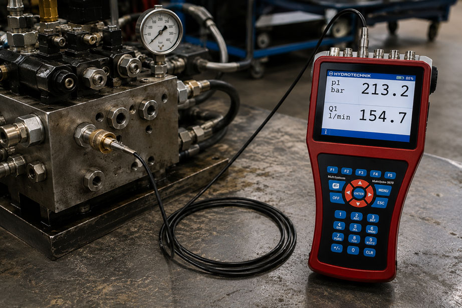
A pressure sensor is connected to a hydraulic system via a MINIMESS® test point and a microbore hose several meters long. The static pressure value appears plausible. During fast switching operations or load changes, however, the measurement shows significantly smaller pressure peaks than expected. In addition, the pressure rise appears to be delayed compared with a measuring point mounted directly on the system.
Is the problem caused by the pressure sensor or the data logger?
Not necessarily.
In dynamic pressure measurements, the microbore hose itself is part of the measurement chain. Hose length, internal diameter, enclosed fluid volume, hose expansion, oil viscosity and, in particular, air bubbles can alter the time response of the pressure signal.
A MINIMESS® hose with a small nominal diameter is generally very well suited to compact service and pressure measuring points. Nevertheless, the following also applies to DN2:
The longer and more compliant the transmission path and the more compressible gas is trapped inside it, the more the actual pressure dynamics at the sensor can differ from the dynamics directly inside the hydraulic line.
This is particularly critical when the objective is not only to measure a static operating pressure, but also, for example:
- short pressure peaks,
- valve switching operations,
- pressure surges,
- pump pulsations,
- rapid load changes,
- control dynamics
.
Suitable microbore lines can be found at ICS Schneider under MINIMESS® hoses. Measuring and recording systems for pressure profiles can be found under pressure data loggers.
Table of Contents
- Why a pressure hose influences measurement dynamics
- Distinguishing between static and dynamic pressure measurement
- How much volume is contained in a DN2 hose?
- Why hose length matters
- Influence of internal diameter
- Hydraulic restriction effect of the microbore line
- Compressibility of oil and hose
- Why air bubbles are particularly problematic
- Bleeding the microbore line correctly
- Oil viscosity and temperature
- Why short pressure peaks can disappear
- Distinguishing between damping and time delay
- The hose line as a dynamic system
- Mount the sensor directly or use a hose?
- Selecting the correct measuring point in the hydraulic system
- Influence of different installation heights
- Influence of the MINIMESS® coupling and adapter
- Why a high sampling rate alone is not sufficient
- Comparing direct measurement and hose measurement
- When a damped measurement can still be useful
- Typical fault patterns
- Systematic diagnosis of a sluggish pressure measurement
- Practical example: pressure peak at a hydraulic valve is missing
- Suitable ICS products
- Conclusion
- FAQ
Why a pressure hose influences measurement dynamics
In an ideal pressure measurement, the pressure at the measuring point would reach the sensor element directly without delay or alteration.
However, if a hose is installed between the measuring point and the sensor, an additional hydraulic system is created.
This consists, among other things, of:
- test coupling,
- hose connection,
- microbore line,
- hydraulic fluid inside the hose,
- possibly trapped air,
- adapters,
- dead volume at the sensor connection,
- pressure sensor.
When the pressure changes, the fluid must transmit forces through this entire path.
Several physical effects act simultaneously:
- flow resistance in the narrow line,
- compressibility of the fluid,
- elastic expansion of the hose,
- inertia of the fluid column,
- significant additional compressibility caused by any trapped air.
In simplified terms, this creates a hydraulic transmission system with its own dynamic behavior.
The sensor therefore does not necessarily measure exactly the same pressure-time profile that exists directly at the original measuring point.
Distinguishing between static and dynamic pressure measurement
When troubleshooting, the first step is to determine what type of pressure is actually to be measured.
Static or slowly changing measurement
Examples include:
- system pressure during steady operation,
- accumulator pressure,
- slowly increasing test pressure,
- supply pressure of a hydraulic system.
After a sufficiently long waiting period, a pressure equilibrium will generally be established in a completely filled connection.
A longer microbore hose can therefore be perfectly adequate for a static measurement.
Dynamic measurement
The situation is different for fast processes:
- a valve switches within a few milliseconds,
- a cylinder moves against a mechanical stop,
- a pump generates pulsations,
- a pressure relief valve opens briefly,
- a load is applied suddenly.
In this case, the relevant question is not only:
What pressure is eventually reached?
But also:
What is the pressure at a specific point in time and how quickly does it change?
This is where the dynamic transfer function of the measuring line becomes relevant.
How much volume is contained in a DN2 hose?
The internal volume of a straight line can be approximated using:
V = π · d² / 4 · L
where:
- V = internal volume,
- d = internal diameter,
- L = hose length.
If an actual internal diameter of 2.0 mm is assumed for illustration, the approximate values are:
| Hose length | Internal volume at 2.0 mm internal diameter |
|---|---|
| 0.5 m | approx. 1.6 ml |
| 1 m | approx. 3.1 ml |
| 2 m | approx. 6.3 ml |
| 5 m | approx. 15.7 ml |
| 10 m | approx. 31.4 ml |
These values are only intended for illustration. The actual internal diameter of the specific hose version must be taken from the data sheet.
At first glance, a few milliliters may appear insignificant.
For dynamic pressure measurement, however, even small volumes can become relevant when combined with:
- a very small flow cross-section,
- an elastic hose wall,
- sensor dead volume,
- or trapped air.
Why hose length matters
The longer the line, the greater several effects become simultaneously.
As length increases, the following also increase:
- fluid volume,
- hydraulic flow resistance,
- effective fluid mass,
- possible elastic hose expansion.
This does not mean that a 5 m microbore hose is fundamentally unsuitable.
It can work perfectly well for a slowly changing pressure measurement.
However, when measuring very short pressure peaks, it should always be checked whether the same measurement produces a different result with:
- 0.5 m,
- 1 m,
- or direct sensor mounting.
For dynamic measurements, the general rule is therefore: keep the pressure line as short as technically practical.
Influence of internal diameter
The internal diameter influences both the enclosed volume and the hydraulic resistance.
A smaller internal diameter reduces the fluid volume.
At the same time, however, the flow resistance of the line increases significantly.
For illustration:
For idealized laminar flow in a circular tube, the hydraulic resistance can be described in simplified form by:
Rhyd = 128 · μ · L / (π · d⁴)
where:
- μ = dynamic viscosity,
- L = line length,
- d = internal diameter.
The decisive term is:
d⁴
In this simplified model, the resistance depends very strongly on the diameter.
This equation does not fully describe the dynamic behavior of a real pressure measuring line. It does, however, demonstrate why small cross-sections can produce a significant restriction effect.
DN2 is nevertheless advantageous for pressure measurement
The small nominal diameter of a MINIMESS® DN2 hose also offers an important advantage:
The enclosed fluid volume is small.
DN2 microbore lines are therefore generally very well suited to compact pressure measurements and service applications.
Nevertheless:
A short DN2 hose and a ten-meter DN2 hose are not dynamically the same measuring arrangement.
Hydraulic restriction effect of the microbore line
During a rapid pressure increase, a small quantity of fluid must be moved or compressed before the new pressure condition can be fully established at the sensor.
The narrow line produces hydraulic resistance.
Combined with the compliance of the system, this results in behavior that can, in simplified terms, be compared with a low-pass filter.
Very slow pressure changes are transmitted almost completely.
Very fast changes, on the other hand, can be:
- attenuated,
- delayed in time,
- altered in shape.
In simplified form, the measuring line can be considered as a combination of:
- hydraulic resistance R of the narrow line,
- hydraulic capacitance C caused by compressible volume and elastic components.
As a qualitative approximation:
τ ~ R · C
The greater the resistance and compliance, the more sluggishly the system may respond.
For accurate calculation of very fast pressure transients, however, a more complete dynamic model of the line is required.
Compressibility of oil and hose
In everyday terminology, hydraulic oil is often described as incompressible.
For many static hydraulic calculations, this approximation is sufficient.
For fast pressure changes and small volumes, however, the finite compressibility of the fluid also becomes relevant.
In addition, a flexible hose expands slightly under pressure.
During a pressure increase, therefore, not only does the fluid have to be compressed.
The hose also accommodates a slightly larger volume as a result of its elastic deformation.
This means:
A flexible hose behaves dynamically differently from a short, very rigid metallic pressure bore connected directly to the sensor.
The actual compliance depends, among other things, on:
- hose material,
- hose construction,
- pressure level,
- temperature,
- length.
Why air bubbles are particularly problematic
One of the most common causes of unexpectedly sluggish pressure measurement is trapped air.
Liquids are far less compressible than gases.
A small air bubble therefore acts like an elastic cushion within an otherwise liquid-filled measuring system.
During a rapid pressure increase, the following must initially occur:
- hydraulic fluid must be displaced toward the sensor,
- the trapped air must be compressed,
- pressure must be built up in this additional compressible volume.
Only then does the sensor fully follow the new pressure condition.
The air bubble therefore significantly increases the hydraulic compliance of the system.
Typical symptoms of trapped air
- slower pressure rise,
- slower pressure decrease,
- rounded pressure peaks,
- lower measured peak values,
- time shift compared with a second measuring point,
- poorer repeatability.
An air bubble directly in front of the sensor element or inside an adapter dead volume can be particularly critical.
Static pressure can still be correct
This point often leads to misinterpretation.
A measuring point containing trapped air can, after a sufficiently long waiting period, indicate a largely plausible static pressure.
However, this does not automatically mean that the measuring point also behaves correctly under dynamic conditions.
A statically plausible measurement does not prove adequate dynamic transmission.
Bleeding the microbore line correctly
For liquid measurement, the measuring line should be filled with the process medium as completely as possible.
Depending on the system, medium and safety requirements, bleeding can be performed, for example, by means of an appropriate:
- flushing procedure,
- bleed point,
- defined hose filling procedure.
The permissible operating pressures and occupational safety requirements of the system must always be observed.
A pressurized hydraulic line must never be opened in an uncontrolled manner.
Pay attention to high points
Air tends to collect at geometric high points.
Hose routing with several loops can therefore be problematic.
For example:
Test point ↓ hose ↑ loop ↓ sensor
can create a location where trapped air cannot easily be transported away.
For demanding dynamic liquid measurements, the line should therefore be routed so that complete filling and bleeding are possible.
Oil viscosity and temperature
The hydraulic flow resistance also depends on the viscosity of the medium.
For many hydraulic oils, viscosity increases significantly as the temperature decreases.
The same measuring line can therefore behave dynamically differently at:
+50 °C
than at:
0 °C
or:
-20 °C
.
A more viscous medium increases the restriction effect of a narrow microbore line.
As a result, the following can increase:
- signal delay,
- damping,
- phase shift.
For comparative measurements, the oil temperature should therefore also be documented.
A pressure profile measured on a cold machine is not necessarily directly comparable with the profile after one hour of operation.
Why short pressure peaks can disappear
Assume that a very short pressure peak occurs directly inside a hydraulic line:
250 bar → 410 bar → 250 bar
within a few milliseconds.
With direct sensor mounting, this peak could be clearly visible.
However, if the pressure is transmitted through a long measuring line with high hydraulic damping, the sensor might record only a significantly broader and lower peak.
The result could then appear more like:
250 bar → 320 bar → 250 bar
even though the actual peak at the original process connection was higher.
The specific values depend entirely on the measuring arrangement and are used here only as an example.
The key point is:
A measuring line can alter the shape of a fast pressure event.
The measurement then no longer shows the exact local peak that existed at the original measuring point.
Distinguishing between damping and time delay
Two different effects can occur with a sluggish pressure measurement.
1. Amplitude damping
A fast pressure change appears smaller.
Example:
actual peak: 400 bar
measured peak: 330 bar
2. Time delay or phase shift
The event appears later than at a directly connected reference measuring point.
Example:
reference signal: peak at t = 100 ms
hose measurement: peak at t = 115 ms
Depending on the system, both effects can occur simultaneously.
In control-system analysis, the time shift is often just as important as the change in amplitude.
The hose line as a dynamic system
A measuring line does not act exclusively as a simple restriction.
During very fast processes, the following also play a role:
- fluid inertia,
- pressure-wave propagation,
- reflections,
- hose expansion,
- sensor volume.
Depending on its geometry, the measuring line can therefore also have its own dynamic characteristics and resonances.
Under unfavorable conditions, certain frequency components may not only be attenuated but may also be locally altered or amplified.
For this reason, in demanding high-dynamic measurements, a microbore line should not simply be regarded as:
“a pressure-carrying cable to the sensor”
.
It is a hydraulic transmission element.
Mount the sensor directly or use a hose?
For the most dynamic pressure measurement possible, a short and rigid hydraulic connection is generally advantageous.
It may therefore be useful to connect the pressure sensor:
- directly to the test coupling,
- via a very short adapter,
- or using the shortest practical microbore hose.
However, direct sensor mounting is not always the best practical solution.
Factors that must be considered include:
- vibration at the measuring point,
- high medium temperature,
- limited installation space,
- risk of mechanical collision,
- sensor size,
- tensile load caused by the cable,
- accessibility.
A microbore hose can therefore be very useful for moving the sensor away from a mechanically or thermally unfavorable location.
The question is therefore not:
“Hose or no hose?”
but:
“Which hose length is appropriate for the required measurement dynamics and installation conditions?”
Selecting the correct measuring point in the hydraulic system
Even a perfectly dynamic measuring line is of little benefit if the pressure is measured at the wrong location.
In highly dynamic hydraulic systems, pressure is not necessarily identical at every location at every point in time.
Between two points there may be:
- valves,
- restrictors,
- filters,
- long pipelines,
- check valves,
- hydraulic accumulators,
- hoses.
A pressure peak directly at the cylinder can therefore look different from the same pressure change measured several meters away at the hydraulic power unit.
Before carrying out a dynamic measurement, it should therefore be clearly defined:
Which local pressure is actually relevant to the diagnosis?
Influence of different installation heights
With longer liquid-filled measuring lines, the height difference between the measuring point and the sensor can also become relevant.
The hydrostatic pressure component can be described by:
Δp = ρ · g · Δh
At very high hydraulic pressures, this effect is often small compared with the actual system pressure.
At low pressure ranges or for precise comparative measurements, however, it may need to be taken into account.
Important:
This hydrostatic height error is a different effect from dynamic damping caused by the hose, viscosity or air.
Influence of the MINIMESS® coupling and adapter
The microbore hose is often not the only component between the process and the pressure sensor.
The complete measurement chain may, for example, consist of:
Hydraulic line → MINIMESS® test coupling → hose connection → DN2 hose → adapter → pressure sensor
Each additional component can:
- add internal volume,
- alter the free cross-section,
- create additional cavities,
- trap air.
Unnecessarily large adapter cavities directly in front of the sensor are particularly unfavorable.
For dynamic measurements, the connection chain should therefore be as:
- short,
- compact,
- completely filled,
- mechanically secure
as possible.
Why a high sampling rate alone is not sufficient
When investigating fast pressure peaks, the sampling rate of the data logger is often checked first.
This is correct – but it is only one part of the measurement chain.
Assume that a data logger samples at:
10 kHz
.
This theoretically corresponds to one measurement point every:
0.1 ms
.
However, if the hydraulic transmission path upstream of the sensor has already significantly smoothed a 2 ms pressure peak, the logger will only see the smoothed signal.
A higher sampling rate cannot reconstruct the original pressure profile in this case.
The complete measurement chain is:
Process → test point → hose → adapter → sensor → electrical signal transmission → data logger → software
The bandwidth of the entire measurement chain is limited by its weakest dynamic element.
A 10 kHz sampling rate therefore does not automatically mean that pressure events up to 10 kHz are measured correctly.
The sensor bandwidth and hydraulic coupling must also be suitable.
Comparing direct measurement and hose measurement
A very effective diagnostic method is to carry out a comparative measurement.
Provided the system and safety conditions allow it, two pressure measurements that are as comparable as possible are performed.
Measurement A
The sensor is connected as directly as possible or through a very short hydraulic connection.
Measurement B
The sensor is connected through the existing microbore line.
Both channels should be recorded:
- synchronously in time,
- with an appropriate sampling rate,
- under the same system operating conditions.
The following should then be compared in particular:
- static pressure,
- peak value,
- rise time,
- time of the pressure peak,
- decay behavior,
- pulsations.
If both measuring points agree statically but differ significantly dynamically, the hydraulic transmission path is an obvious point to investigate.
When a damped measurement can still be useful
Not every form of damping is automatically undesirable.
For certain applications, the main variables of interest are:
- average operating pressure,
- long-term pressure changes,
- slow load changes,
- trend values.
In these cases, very high-frequency pressure pulsations may even be undesirable.
Defined damping can then result in a smoother signal that is easier to evaluate.
It only becomes problematic if the measuring arrangement has unknown or changing damping characteristics.
For trend measurements, therefore:
The hydraulic connection configuration should remain as constant as possible.
It would, for example, be problematic if:
- measurement 1 is performed with 1 m DN2,
- measurement 2 with 5 m DN2,
- measurement 3 with the sensor mounted directly
and all three curves are subsequently compared as if they came from an identical measurement chain.
Typical fault patterns in pressure measurements using microbore hoses
| Observation | Possible cause | Recommended check |
|---|---|---|
| Static pressure is correct, but fast pressure peaks are missing | Dynamic damping of the hose/sensor arrangement | Compare with a shorter line or direct sensor mounting |
| Pressure rise is significantly delayed | Long line, high hydraulic compliance or air in the system | Reduce hose length and bleed the line completely |
| Pressure rise and pressure decrease are strongly rounded | Hydraulic low-pass effect | Check hose volume, sensor dead volume and trapped air |
| Measurement is significantly more sluggish when the machine is cold | Higher oil viscosity | Document oil temperature and compare measurements at similar temperatures |
| Measurement suddenly behaves differently after reconnecting | Air trapped during coupling or filling | Bleed the measuring line again |
| Visible air bubble in the hose | Incomplete filling | Remove the bubble using a suitable and safe procedure |
| Short hose shows a higher pressure peak than a long hose | Different dynamic transmission behavior | Compare the same sensor and logger using different hose lengths |
| Logger with a higher sampling rate still does not show an additional peak | Pressure signal has already been hydraulically damped | Check the hydraulic coupling upstream of the sensor |
| Measured values differ only during fast valve switching | Static transmission is correct, but dynamic bandwidth differs | Perform a step-response test or synchronous comparative measurement |
| Measurement signal oscillates after a fast pressure change | Possible dynamic resonance of the measuring line | Check hose length, connection volume and direct reference measurement |
| Measurement changes after replacing an adapter | Changed dead volume or free cross-section | Compare adapter geometry and the complete measurement chain |
| Pressure is permanently shifted by a small amount | Height difference or sensor offset | Check hydrostatic height component and zero point |
| Pressure peak occurs later at the sensor than at the reference sensor | Phase shift or delayed pressure transmission | Record channels synchronously and determine the time offset |
Systematic diagnosis of a sluggish pressure measurement
If a MINIMESS® measuring point responds too slowly, the cause should be narrowed down systematically.
- Define the measurement task: Is the objective to measure static pressure, a slow pressure change or a short pressure peak?
- Determine the expected event duration: Is the event in the range of seconds, milliseconds or even faster?
- Check the measuring point: Is the connection actually located where the relevant pressure event occurs?
- Document the hose type: Record DN2/DN4, material and specific version.
- Measure the hose length: Do not use only the direct distance between the sensor and the system.
- Remove unnecessary excess hose: Use the shortest practical connection for dynamic measurements.
- Check hose routing: Avoid loops, kinks and unfavorable high points.
- Check the line for air: Particularly after initial connection or modification.
- Bleed the line safely: Only in accordance with the requirements of the system and measuring components.
- Check adapters: Look for unnecessary dead volumes or very small additional bores.
- Check the coupling: Ensure complete actuation and an unrestricted measuring path.
- Record oil temperature: Compare cold and warm operating conditions.
- Check sensor bandwidth: The sensor itself must be fast enough for the event.
- Check logger sampling rate: Record enough measurement points for the event of interest.
- Check filter settings: Electronic or software averaging can create additional damping.
- Test a short hose: Use the same sensor with a significantly shorter connection.
- Perform a direct measurement: If technically and safely possible, connect the sensor directly to the measuring point.
- Compare measurements synchronously: Evaluate peak value, rise time and time offset.
- Document the measurement chain: Record hose, length, sensor, sampling rate and filter settings.
Practical example: pressure peak at a hydraulic valve is missing
A hydraulic power unit is being investigated because a hose is regularly subjected to high mechanical stress.
A short pressure peak during rapid closing of a directional control valve is suspected.
The existing setup consists of:
MINIMESS® test point → 5 m DN2 microbore hose → pressure sensor → data logger
Step 1: first measurement
The normal operating pressure is approximately:
220 bar
During switching, the measured pressure briefly rises only to:
255 bar
The rise appears relatively smooth.
Step 2: increase the sampling rate
The measurement is repeated with a significantly higher sampling rate.
The curve now contains more measurement points, but the peak value remains almost unchanged.
This suggests that the limitation is not caused solely by the data logger.
Step 3: inspect the measuring line
The DN2 hose is five meters long and contains several loops.
In addition, a small air bubble in the measuring line after reconnection cannot be ruled out.
Step 4: shorten and bleed the hose
For diagnostic purposes – while observing all necessary safety requirements – a significantly shorter measuring line is used and completely filled with the medium.
Step 5: repeat the measurement
During the same valve switching operation, a significantly steeper pressure rise is now visible.
The peak value is, for example:
315 bar
These values are only examples used to illustrate the procedure.
Step 6: move the sensor as close to the measuring point as possible
For a further comparative measurement, the hydraulic connection is shortened again.
An even shorter and higher peak is now visible.
This clearly shows:
The original setup significantly influenced the dynamic pressure profile.
Step 7: redefine the measurement objective
For future diagnostics, a distinction is made between:
- a long or conveniently routed line for general service and static pressure measurement,
- a short hydraulic connection for targeted analysis of fast pressure peaks.
Result: The sensor and data logger were not the actual cause. The hydraulic connection between the process and the sensor limited the dynamic information provided by the measurement.
Suitable ICS products for dynamic pressure measurements via MINIMESS®
MINIMESS® hoses – DN2/DN4 microbore lines for service and pressure measurement
The MINIMESS® hoses offered by ICS are microbore hose assemblies in DN2 and DN4.
They are suitable for connecting measuring points to:
- pressure sensors,
- pressure gauges,
- test equipment,
- mobile measuring systems.
Different operating pressures are available for the versions offered by ICS depending on the hose and fitting.
For DN2, for example, versions rated up to 630 bar are available.
The small nominal diameter provides a very small fluid volume and is therefore particularly useful for compact pressure measuring points.
For dynamic measurements, however, it is still advisable to install the hose:
- as short as practical,
- without unnecessary loops,
- without kinks,
- as completely filled with liquid as possible.
ICS supplies the lines with different hose materials, lengths and connection fittings to suit the application.
Further information can be found under MINIMESS® hoses at ICS Schneider.
MINIMESS® couplings – defined measuring points on hydraulic systems
MINIMESS® couplings provide compact measuring and service connections on hydraulic systems.
They can, for example, be combined with DN2 or DN4 microbore lines.
For dynamic pressure measurement, not only the hose but the complete connection chain should be considered:
Test coupling → hose connection → microbore line → adapter → sensor
Unnecessary adapters and large dead volumes should be avoided when fast pressure changes are to be measured.
An overview can be found under MINIMESS® couplings and hoses at ICS Schneider.
MultiSystem 5070 – dynamic data acquisition for hydraulic diagnostics
The MultiSystem 5070 is particularly suitable for mobile measuring and diagnostic tasks on hydraulic systems.
The instrument offered by ICS features, among other things:
- 5″ color display,
- multiple analog measuring inputs,
- 32 additional special channels for calculations or CAN,
- 500 measurement series,
- up to 6 million measured values per measurement series,
- sampling rate up to 10 kHz,
- two separate CAN interfaces.
This makes it possible, for example, to record simultaneously:
- pressure,
- temperature,
- flow rate
and compare them with each other over time.
The high sampling rate is particularly useful when searching for pressure peaks.
However, it must not be confused with the bandwidth of the complete pressure measurement chain.
If a long or air-filled microbore line has already damped the pressure impulse before it reaches the sensor, the MultiSystem 5070 cannot subsequently reconstruct the original process pressure.
The sensor, hydraulic connection and data logger must therefore all be matched to the required measurement dynamics.
Further information can be found under MultiSystem 5070 at ICS Schneider.
Which measuring arrangement is suitable for the task?
| Measurement task | Recommended configuration |
|---|---|
| Static operating pressure | MINIMESS® microbore hose of suitable length |
| Slow pressure trends | DN2/DN4 according to pressure, length and connection requirements |
| Mobile service testing | MINIMESS® test point + microbore hose + pressure sensor |
| Fast valve switching operation | Shortest possible, completely liquid-filled hydraulic connection |
| Short pressure peaks | Sensor as close as possible to the measuring point and high sampling rate |
| Comparison of several pressure points | Synchronous multi-channel measuring system such as MultiSystem 5070 |
| Unknown damping caused by existing hose | Compare with a shorter line or direct measurement |
Further measuring instruments for recording pressure profiles can be found under pressure data loggers at ICS Schneider.
Conclusion
A MINIMESS® microbore hose is a very practical solution for connecting a pressure sensor quickly and safely to an existing measuring point.
For dynamic pressure measurements, however, the hose must not be regarded as a metrologically neutral connecting element.
The complete hydraulic connection has:
- internal volume,
- flow resistance,
- fluid inertia,
- compressibility,
- elastic compliance.
As a result, fast pressure changes can be damped and altered in time.
Trapped air is particularly critical. Even a relatively small gas volume significantly increases the compliance of the measuring line and can substantially round off an originally fast pressure impulse.
Oil temperature also plays a role. At low temperatures, the viscosity of typical hydraulic oils increases, which can increase the restriction effect of a narrow microbore line.
For measuring fast pressure peaks, the hydraulic connection should therefore be as:
- short,
- compact,
- completely filled with liquid,
- free of unnecessary dead volumes
as possible.
At the same time, the sensor and data logger must also be fast enough.
A high data logger sampling rate alone is not sufficient. A signal that has already been hydraulically damped cannot subsequently be restored to its original profile by digital recording.
If there is any doubt, a comparative measurement is particularly informative:
Measure with the existing hose → bleed the line → shorten the hose → if necessary connect the sensor directly → compare the curves synchronously.
For practical applications, the recommended procedure is therefore:
Define the measurement objective → determine the required dynamics → select the correct measuring point → keep the MINIMESS® hose as short as practical → remove all air → avoid unnecessary adapters → document oil temperature → check sensor bandwidth → select a sufficient sampling rate → compare direct and hose measurements.
FAQ: Sluggish pressure measurement with a MINIMESS® microbore hose
Why does my MINIMESS® pressure measurement respond so slowly?
Possible causes include a long microbore line, trapped air, large connection volumes, high oil viscosity, additional restrictions or insufficient bandwidth of the sensor or measuring instrument.
Does a MINIMESS® hose damp pressure peaks?
A microbore line can influence the amplitude and time response of fast pressure changes. The extent of this effect depends, among other things, on length, internal diameter, medium, temperature, hose construction and trapped air.
Is DN2 suitable for dynamic pressure measurements?
DN2 has a very small internal volume and is therefore generally well suited to compact pressure measurements. For very fast processes, however, hose length and the complete hydraulic connection chain must still be taken into account.
Why is a short DN2 hose faster than a long one?
As hose length increases, the enclosed fluid volume and hydraulic resistance increase, among other factors. This can change the dynamic behavior of the measuring line.
How much oil is contained in one meter of DN2 hose?
Assuming an actual internal diameter of 2.0 mm, the geometric volume is approximately 3.1 ml per meter. The actual hose version may differ, so the true internal diameter should be taken from the relevant data sheet.
How do you calculate the internal volume of a microbore hose?
Approximately using V = π × d² / 4 × L. Here, d is the internal diameter and L is the length.
Why is air inside a pressure measuring hose problematic?
Air is significantly more compressible than hydraulic fluid. An air bubble therefore increases the compliance of the measuring line and can delay or damp fast pressure changes.
Can an air bubble hide a pressure peak?
Yes. Particularly short pressure peaks can be significantly rounded off or reduced in measured amplitude due to the additional compressibility of a gas volume.
Can the static pressure still be correct even if there is air in the hose?
Yes. After sufficient stabilization, a plausible static pressure can be reached even though the dynamic behavior of the measuring point is significantly impaired.
How can I identify air in the microbore hose?
Indications can include an unusually slow step response, different results after reconnecting the hose or significantly different behavior compared with a directly connected reference measuring point.
How do I bleed a MINIMESS® hose?
The line should be completely filled with the medium and bled using a procedure approved for the respective system. For pressurized hydraulic systems, the safety and installation requirements of the components used must always be observed.
Can I bleed a pressure hose while it is pressurized?
Only if the measuring system, fittings and working procedure are explicitly designed for this. Hydraulic fluid under high pressure can cause serious injuries. Manufacturer instructions and plant safety rules must be followed.
Why does oil temperature influence pressure measurement?
The viscosity of typical hydraulic oils depends on temperature. At low temperatures, a more viscous oil can increase the hydraulic resistance of a narrow line.
Is pressure measurement slower with cold oil?
This can be the case. Higher viscosity can contribute to greater damping or delay, particularly in long and narrow measuring lines.
What is the restriction effect of a microbore hose?
The small internal diameter creates hydraulic flow resistance. Together with the compliance of the enclosed volume, this can create a low-pass effect for fast pressure changes.
Is a smaller internal diameter always faster?
No. A smaller internal diameter reduces the enclosed fluid volume, but at the same time increases hydraulic resistance. The actual dynamic behavior results from the entire combination.
Is DN4 faster than DN2?
Not necessarily. DN4 has a larger cross-section and lower flow resistance, but also a significantly larger enclosed volume. Which version is more suitable depends on length, measurement task and configuration.
Why should the measuring hose be as short as possible?
A shorter line reduces fluid volume, line resistance and potential hose expansion, thereby improving pressure transmission in many dynamic applications.
How long can a MINIMESS® hose be for dynamic measurements?
There is no universal maximum length. The permissible length depends on the required frequency or rise time, sensor, hose type, medium and required measurement uncertainty.
Can I measure pressure peaks using a 5 m DN2 hose?
Pressure changes can generally be transmitted. However, whether very short peaks are measured quantitatively correctly must be verified for the specific measurement chain. A comparative measurement using a shorter connection is very useful for this purpose.
Which is better: connecting the pressure sensor directly or via MINIMESS®?
For maximum dynamic response, a short and rigid hydraulic connection is advantageous. MINIMESS® offers major advantages in terms of service access, flexibility and temporary measurement. The choice depends on the measurement objective.
Can I connect the sensor directly to the MINIMESS® coupling?
A very short hydraulic connection can be realized using an appropriate connection solution suitable for the sensor and test coupling. Pressure range, thread, seal and mechanical load capacity must all be compatible.
Why should the pressure sensor be positioned as close as possible to the measuring point?
This shortens the hydraulic transmission path. Particularly for fast pressure transients, this can improve dynamic reproduction.
Can a long measuring line cause a time delay?
Yes. A real hydraulic measuring line has its own dynamic transfer behavior. Fast signal components can therefore appear shifted in time compared with a direct measurement.
What is the difference between damping and delay?
Damping primarily changes the amplitude of a signal. Delay or phase shift changes its timing. Both effects can occur simultaneously.
Can a microbore hose generate resonances?
A liquid-filled line has its own dynamic characteristics due to fluid inertia, compressibility and elastic components. Resonance and reflection effects can therefore also become relevant during very fast processes.
Does the hose material influence pressure measurement?
Yes. Different hose constructions have different mechanical compliance characteristics. This can influence dynamic behavior.
Do adapters influence measurement dynamics?
Yes. Adapters can add dead volume or small flow cross-sections. For highly dynamic measurements, the connection chain should therefore be kept as compact as possible.
What does dead volume mean in pressure measurement?
Dead volume is an additional cavity filled with the medium, for example inside an adapter or sensor connection. Larger volumes increase the amount of medium that must be compressed or displaced during a pressure change.
Can the MINIMESS® coupling itself influence the measurement?
The coupling is also part of the hydraulic transmission path. When troubleshooting, the entire chain consisting of test point, coupling, hose, adapter and sensor should therefore be considered.
Why do I still not see a pressure peak with a higher sampling rate?
If the hydraulic measuring line has already damped the peak before it reaches the pressure sensor, a higher digital sampling rate cannot restore the original signal.
How high should the sampling rate be for pressure peaks?
This depends on the duration and frequency content of the event being investigated. The sampling rate must be sufficiently high, while the sensor and hydraulic coupling must also transmit the required dynamics.
Does a 10 kHz sampling rate mean that I can measure 10 kHz pressure oscillations?
No. The sampling rate alone does not define the usable bandwidth of the complete measurement chain. Sensor frequency response, analog signal conditioning and hydraulic coupling must also be taken into account.
How can I test whether my hose dampens pressure peaks?
A particularly informative method is the synchronous comparison of a pressure measurement connected as directly as possible with a measurement taken through the existing microbore hose.
What should I evaluate in a comparative measurement?
At minimum, static pressure, peak value, rise time, time of maximum, decay behavior and, where applicable, the frequency spectrum should be compared.
Can software compensate for hose damping?
If the transfer function of the system is known with sufficient accuracy and remains stable, certain correction methods may in principle be possible. For normal service applications, however, it is considerably more reliable to design the hydraulic measurement chain correctly from the outset.
Is damping in a pressure measurement always undesirable?
No. For trend or average-value measurements, a certain amount of damping can even be desirable. It becomes problematic when short pressure peaks are part of the diagnosis or when the damping changes between comparative measurements.
Can I measure static pressure using a long MINIMESS® hose?
Yes. For static and slowly changing measurements, longer microbore lines can be used without problems in many applications, provided that pressure range, medium, temperature and hose version are suitable.
Why do two identical sensors at different measuring points show different values?
In addition to sensor tolerances, different measuring points, hose lengths, adapters, air volumes and local process dynamics may cause the deviation.
Does the height difference between the sensor and the measuring point matter?
In liquid-filled lines, a hydrostatic pressure component of Δp = ρ × g × Δh occurs. At high hydraulic pressures this is often small, but at low pressure ranges and in precision measurements it can become relevant.
What should remain constant for trend measurements?
The measuring point, hose type, hose length, sensor, adapter, measuring range, sampling rate, filter settings and, where possible, the operating and temperature conditions should remain comparable.
What is the MultiSystem 5070?
The MultiSystem 5070 is a mobile multi-channel measuring system for acquiring and storing various sensor signals, including pressure, temperature and flow measurements on fluid systems.
What sampling rate does the MultiSystem 5070 provide?
ICS specifies a sampling rate of up to 10 kHz for the MultiSystem 5070.
Can the MultiSystem 5070 record several pressure points simultaneously?
The instrument has multiple measuring inputs and is therefore suitable for multi-channel measurements. This allows different pressure points to be compared over time, for example.
Why is synchronous multi-channel measurement useful in hydraulic diagnostics?
It makes it possible to determine when a pressure event occurs at different locations and how the amplitude or time response differs between the measuring points.
What operating pressure is available for MINIMESS® DN2 hoses?
Depending on the hose version and fitting, ICS offers DN2 lines with operating pressures of up to 630 bar. For the specific hose assembly, the permissible combination of hose and connection fittings is always decisive.
Where can I find MINIMESS® microbore hoses at ICS Schneider?
An overview can be found under MINIMESS® hoses at ICS Schneider.
Where can I find pressure data loggers at ICS Schneider?
An overview can be found under pressure data loggers at ICS Schneider.