


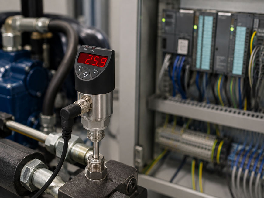
An electronic temperature switch may, for example, correctly show 72 °C on its display while the PLC input remains permanently at 0. In another case, the input may work in principle but switch exactly opposite to the required logic. This often does not indicate a defective temperature switch. More common causes are an incompatible PNP/NPN output, an incorrect reference potential, unsuitable NO/NC parameterization or incorrect terminal assignment.
With electronic temperature switches, several functions must therefore be distinguished. The sensor first measures the temperature. The electronics then compare this value with the configured switching point and control a transistor output accordingly. Depending on the device, a second switching output, an analog 4 … 20 mA or 0 … 10 V signal, or a digital interface such as IO-Link may also be available.
For reliable connection to a PLC, supply voltage, PNP or NPN switching principle, common reference potential, PLC input type, switching logic, hysteresis and permissible load current must be considered together.
Suitable solutions are available from ICS Schneider under Temperature Measurement Technology and specifically under Temperature Switches and Thermostats.
For industrial machinery and hydraulic applications, ICS Schneider offers, for example, the WIKA TSD-30 electronic temperature switch with display. Depending on the version, PNP or optionally NPN switching outputs, an analog signal and IO-Link are available.
Table of Contents
- What an electronic temperature switch actually switches
- How a PNP output works
- How an NPN output works
- Direct comparison of PNP and NPN
- Connect a PNP temperature switch to a PLC
- Why 0 V is important as a common reference
- Understanding normally open and normally closed functions in electronic switches
- Correctly set switching point and hysteresis
- Use the window function for temperature ranges
- Correctly evaluate the permissible switching current
- Do not switch relays and solenoid valves directly without checking
- Use switching output and analog output simultaneously
- Correctly scale 4–20 mA in the PLC
- IO-Link as an alternative to conventional wiring
- Why the PLC can be faster than the temperature measurement
- Consider installation position and insertion depth
- Distinguish between process and ambient temperature
- M12 connection, cables and EMC
- Systematically diagnose the switching output
- Typical errors when connecting to a PLC
- Practical example: high-temperature alarm at 80 °C
- Distinguish between process switching and safety functions
- Systematically commission a temperature switch
- WIKA TSD-30 at ICS Schneider
- Conclusion
- FAQ
What an electronic temperature switch actually switches
An electronic temperature switch combines several functions in one device.
A typical measurement chain consists of:
temperature sensor → measuring electronics → limit evaluation → transistor output → PLC
The actual temperature sensing element can, for example, be a:
Pt1000
.
The electronics calculate the current temperature from the sensor signal and compare it with the configured switching points.
This comparison generates a digital output signal.
The output is often not a potential-free contact
This is one of the most important differences compared with conventional mechanical thermostats.
A mechanical temperature switch may, for example, have a genuine:
potential-free changeover contact
.
An electronic PNP or NPN output, on the other hand, is a semiconductor output and requires a power supply.
The connection logic must therefore match the PLC.
How a PNP output works
When active, a PNP switching output switches the positive supply voltage to the signal output.
In simplified form:
PNP active → output ≈ +U
With a typical 24 V control voltage, this means:
temperature switch switches → PLC input receives a positive signal
The current flows, in simplified form:
+24 V → sensor electronics → PNP output → PLC digital input → 0 V
PNP is therefore also referred to as sourcing
When switched on, the sensor supplies positive current to the input.
The corresponding PLC input must be electrically compatible with this arrangement.
PNP sensors are commonly used in many industrial 24 V DC systems. However, this does not mean that every PLC input is automatically suitable for every PNP circuit.
The input circuit of the specific PLC module is always decisive.
How an NPN output works
An NPN output operates in the opposite direction.
When active, the transistor output connects the signal approximately to:
0 V
The sensor therefore pulls the current toward ground.
In simplified form:
NPN active → output is switched to 0 V
The current path may, for example, be:
+24 V → PLC input or load → NPN output → 0 V
NPN is often referred to as sinking
The output sinks the current or conducts it toward 0 V.
The PLC must be wired accordingly.
A PNP sensor therefore cannot simply be replaced by an NPN sensor without checking the input circuit.
Direct comparison of PNP and NPN
| Property | PNP | NPN |
|---|---|---|
| Active output | switches positive supply voltage | switches to 0 V |
| English designation | sourcing output | sinking output |
| Typical signal state in a 24 V system | approximately +24 V | approximately 0 V |
| Required PLC input circuit | suitable for a sourcing sensor | suitable for a sinking sensor |
| Common application | European machinery and plant engineering | also widely used depending on application and market |
PNP and NPN describe the electrical output circuit. They do not indicate whether the output operates as normally open or normally closed.
These two characteristics must be considered separately.
Connect a PNP temperature switch to a PLC
In a typical 24 V DC application, a PNP temperature switch is connected as follows:
Sensor U+ → +24 V DC
Sensor U- → 0 V
PNP switching output → PLC digital input
PLC input reference → 0 V
Example
The temperature switch monitors the oil temperature of a hydraulic power unit.
The switching point is set to:
80 °C
.
If the temperature rises above the switching point, the PNP output becomes active.
A HIGH signal is then present at the PLC input.
The PLC can subsequently, for example:
- generate a warning message,
- switch on a fan,
- reduce machine output,
- withdraw process enable.
The specific pin assignment must always match the device version
Different output configurations are available for the WIKA TSD-30.
For a 4-pin M12 version with one switching output and analog signal, the following may apply, for example:
| Function | Pin |
|---|---|
| U+ | 1 |
| U- | 3 |
| SP1 | 4 |
| Analog signal S+ | 2 |
For a 5-pin version with two switching outputs and an analog signal, the following may apply, for example:
| Function | Pin |
|---|---|
| U+ | 1 |
| U- | 3 |
| SP1 | 4 |
| SP2 | 2 |
| Analog signal S+ | 5 |
This pin assignment must not be applied generally to other temperature switches or other TSD-30 output versions. Before connection, the specific device identification and operating instructions must be checked.
Why 0 V is important as a common reference
A common error occurs when the temperature switch and PLC are both supplied with 24 V but do not have a suitable common reference potential.
The PLC input does not evaluate an abstract voltage, but a voltage between two defined potentials.
In a typical non-isolated PNP circuit, the following must therefore be electrically connected correctly:
0 V of the sensor
and:
0 V of the PLC input supply
.
Typical fault symptom
For example, a multimeter measures:
23,8 V
at the sensor output.
The PLC input nevertheless remains inactive.
Possible cause:
The measurement was taken against the sensor supply reference, while the PLC input uses a different reference potential.
Different conditions apply with galvanic isolation
If the input module has a galvanically isolated input circuit, the wiring must be configured according to the PLC documentation.
For this reason, wiring should not be carried out solely according to cable colors.
Understanding normally open and normally closed functions in electronic switches
In addition to PNP or NPN, the switching function is often configurable.
Typical terms are:
NO = Normally Open
and:
NC = Normally Closed
Electronic outputs are not necessarily mechanical contacts
These designations describe the required output logic.
Normally open example
A temperature switch is intended to activate a warning when the temperature exceeds:
80 °C
.
Below the switching point:
output inactive
Above the switching point:
output active
This corresponds to typical normally open logic for a high-temperature alarm.
Normally closed example
With normally closed logic, the output can be active during normal operation and become inactive when the switching condition is reached.
This can be useful for certain diagnostic concepts.
However, electronic NC parameterization must not automatically be regarded as a completely fail-safe, wire-break-monitored safety function.
Correctly set switching point and hysteresis
Without hysteresis, a temperature switch could continuously switch on and off directly around the limit value.
Assume the setpoint is:
80 °C
and the process fluctuates between:
79,9 °C
and:
80,1 °C
.
Without sufficient hysteresis, the output could continuously change state.
Hysteresis defines two different switching points
For example:
switching point SP = 80 °C
reset point RP = 75 °C
The hysteresis is therefore:
H = SP - RP
H = 5 K
As the temperature rises, the alarm becomes active at 80 °C and is not reset until the temperature has fallen to 75 °C.
The hysteresis must match the process
Hysteresis that is too small can lead to frequent switching operations.
Hysteresis that is too large can, on the other hand, cause a:
- fan,
- cooler,
- heater,
- alarm
to remain active unnecessarily long.
Use the window function for temperature ranges
Many electronic temperature switches can monitor more than just a single limit value.
A window function makes it possible to evaluate a permissible temperature range.
For example:
60 … 80 °C = permissible range
This allows two limits to be combined in one logical function
Depending on the parameterization, the output can be:
- active inside the window,
- active outside the window.
This can be useful, for example, for:
- process enable signals,
- temperature control units,
- cooling circuits,
- lubricating oil systems,
- machine tools.
With the WIKA TSD-30, switching point, normally open/normally closed function as well as window and hysteresis functions can be parameterized.
Correctly evaluate the permissible switching current
The maximum switching current of the temperature switch specifies the maximum output current that the transistor output may carry.
This value must not be confused with:
- the current consumption of the sensor,
- the maximum current capacity of the power supply,
- the current consumption of the PLC input.
A PLC digital input normally requires only a comparatively small current
Therefore, when an electronic switching output is connected directly to a PLC input, the load is often well below the maximum permissible switching current.
The situation is different when directly switching a load
For example:
- relay,
- solenoid valve,
- indicator light,
- small contactor,
- buzzer.
In this case, the actual load current must be checked.
Not only the steady-state rated current is important. Inrush current and switch-off behavior may also be relevant.
For the WIKA TSD-30
the maximum permissible switching current without IO-Link is:
250 mA
Different limits apply with IO-Link:
SP1: max. 100 mA
SP2: max. 250 mA
Due to the circuit design, the switching voltage is slightly below the supply voltage.
The specification of 250 mA does not mean that any 24 V load with a rated current below 250 mA can automatically be switched directly.
Do not switch relays and solenoid valves directly without checking
Inductive loads have a particular characteristic when switched off.
Energy is stored in the magnetic field of coils in:
- relays,
- contactors,
- solenoid valves.
If the current is interrupted suddenly, a high counter-voltage can be generated.
The output stage must be protected against this voltage
Depending on the load and circuit, suitable solutions may include:
- flyback diode for DC coils,
- suitable protective circuitry,
- interposing relay,
- separate transistor driver.
Which protective measure is permissible depends on the sensor, load and required switch-off time.
For a PLC, a cleaner solution is often
to use the temperature switch exclusively as an information signal:
temperature switch → PLC digital input
and then switch the actual power load via a suitable PLC output or corresponding interface device.
This keeps the measurement circuit and power circuit clearly separated.
Use switching output and analog output simultaneously
Depending on the version, an electronic temperature switch can provide a continuous analog value in addition to the digital limit signal.
Depending on the configuration, the WIKA TSD-30 is available, for example, with:
- one PNP switching output +
4 … 20 mA, - one PNP switching output +
0 … 10 V, - two PNP switching outputs,
- two PNP switching outputs +
4 … 20 mA, - two PNP switching outputs +
0 … 10 V.
NPN versions are also available.
This allows the PLC to receive two different types of information
For example:
SP1 → high-temperature alarm
and simultaneously:
4 … 20 mA → current temperature
The PLC can therefore record the analog temperature trend while additionally using the digital switching output as an independent process limit value.
Correctly scale 4–20 mA in the PLC
If a current signal is also used, the PLC must know which temperature range is assigned to:
4 … 20 mA
.
Example
Assume:
4 mA = 0 °C
20 mA = 100 °C
In simplified form:
T = (I - 4 mA) / 16 mA × 100 °C
At:
I = 12 mA
the result is:
T = 50 °C
The analog value and switching output perform different tasks
The analog signal continuously provides the process variable.
The PNP output, on the other hand, provides only a digital state:
0 or 1
The two signals should therefore also be documented separately in the PLC.
IO-Link as an alternative to conventional wiring
IO-Link enables digital communication between the sensor and an IO-Link master.
In addition to the process value, depending on the device, it can transmit:
- parameters,
- switching points,
- diagnostic data,
- device information.
Advantage when replacing a device
In appropriately configured systems, sensor parameters can be managed centrally and reassigned to a replacement device.
This can simplify commissioning and service.
With the TSD-30
IO-Link Revision 1.1 is optionally available.
With the IO-Link version:
SP1 is always PNP
and SP1 has a lower maximum switching current than the standard version.
This must be taken into account during planning.
Why the PLC can be faster than the temperature measurement
A PLC digital input can respond within milliseconds.
However, this does not mean that an actual temperature change reaches the temperature switch just as quickly.
The overall response time consists, in simplified form, of:
thermal heat transfer + sensor response + electronic evaluation + PLC input + PLC program
In temperature measurement, the thermal side often dominates
Relevant factors include:
- probe diameter,
- insertion depth,
- flow velocity of the medium,
- thermowell,
- heat transfer,
- temperature difference.
For the WIKA TSD-30 probe, response times of:
T05 < 5 s
and:
T09 < 10 s
are specified under defined test conditions.
In the actual installation, the total temperature response may differ depending on the installation conditions.
Consider installation position and insertion depth
An electrically correctly connected temperature switch can still measure an incorrect or delayed temperature.
Insufficient insertion depth
can cause heat to be conducted away or introduced via:
- process connection,
- pipe wall,
- housing,
- ambient environment.
The sensor then does not measure only the actual medium temperature.
Large temperature differences are particularly critical
For example:
medium = 120 °C
ambient = 20 °C
With unfavorable installation, considerable heat flow can occur through the process connection.
The achievable measurement error therefore depends on more than just the electrical accuracy of the sensing element.
The measurement accuracy of the sensing element and the accuracy of the actual measuring point are not the same thing.
Distinguish between process and ambient temperature
A temperature sensor may be designed for a comparatively high medium temperature while its electronics can tolerate only a significantly lower ambient temperature.
These two specifications must not be confused.
With the TSD-30
temperature measuring ranges up to:
0 … +150 °C
are available depending on the version.
However, additional installation and ambient restrictions apply to certain high process temperatures.
For process medium temperatures above:
80 °C
the manufacturer specifies that particular attention must be paid to ensuring that the permissible housing temperature is not exceeded.
A suitable longer probe or appropriate thermal decoupling may therefore be required.
M12 connection, cables and EMC
Electronic temperature switches are frequently connected using M12 connectors.
This simplifies installation but does not automatically prevent wiring errors.
Check before connecting
- number of connector pins,
- pin assignment,
- output version,
- supply voltage,
- PNP or NPN,
- analog signal,
- wiring assignment of the mating connector.
Cable color alone is not sufficient documentation
Standardized sensor cables often use defined conductor colors. However, the assignment may differ with preassembled or customer-specific cables.
The decisive information is therefore:
device pin assignment + wiring assignment of the cable used
Consider EMC
Temperature switches are often installed in machines containing:
- frequency converters,
- motor cables,
- contactors,
- solenoid valves,
- high switching currents.
Signal and supply cables should therefore be routed in accordance with the system and manufacturer requirements.
Systematically diagnose the switching output
If the PLC input does not respond as expected, the sensor should not immediately be replaced.
A systematic check is usually faster.
1. Check the supply voltage
Measure directly at the sensor:
U+ against U-
The voltage must be within the permissible device specification.
2. Check the current temperature
Does the device display a plausible temperature?
If the temperature display itself is already incorrect, the problem is probably not limited to the switching output.
3. Check the switching point
For example:
SP1 = 80 °C
RP1 = 75 °C
4. Check the switching logic
Is the output parameterized as:
NO
or:
NC
?
5. Check PNP/NPN
Does the output match the PLC input being used?
6. Measure the output voltage
For a PNP output, the voltage can be measured between:
SP and 0 V
.
The output should change its electrical state according to the switching condition.
7. Check the PLC input separately
If permitted and in accordance with the PLC documentation, it can be checked whether the input module responds to a defined test signal.
8. Check the PLC software
The physical input may be working correctly while the following prevent the required function:
- incorrect input address,
- inverted software logic,
- filter time,
- program interlock.
Typical errors when connecting to a PLC
| Observation | Possible cause | Recommended check |
|---|---|---|
| Temperature display correct, PLC input always 0 | PNP/NPN incompatible or missing reference potential | Check output type and 0 V connection |
| PLC input always 1 | Normally closed logic configured instead of normally open | Check NO/NC function |
| Output constantly switches on and off | Hysteresis too small | Check switching and reset points |
| Output switches at the wrong temperature | Switching point or unit configured incorrectly | Check SP/RP and °C/°F |
| Sensor works without load but is unreliable with a relay | Load current or inductive switch-off voltage | Check load data and protective circuitry |
| Switching output works, analog value does not | Incorrect pin or incorrect PLC input configuration | Check S+ and analog input circuit type |
| Analog value is correct, digital output is not | Incorrect switching mode | Check PNP/NPN, NO/NC, window and hysteresis |
| Switching point is reached with a significant delay | Thermal response time or unsuitable installation | Check insertion depth and heat transfer |
| Temperature permanently too low | Heat dissipation through process connection | Check probe length and installation position |
| Display becomes implausible in a hot process | Electronics thermally overloaded | Check ambient and housing temperature |
| PLC sporadically reports incorrect states | EMC, cable routing or unstable power supply | Check power supply and wiring |
| Incorrect function after sensor replacement | Different output or pin version | Compare order code and connection diagram |
Practical example: high-temperature alarm at 80 °C
A hydraulic power unit is intended to report an alarm to the PLC if the oil temperature becomes too high.
An electronic temperature switch with a PNP output is used.
Requirement
Activate alarm at:
80 °C
Reset alarm at:
75 °C
Supply:
24 V DC
Parameterization
The switching point is set to:
SP1 = 80 °C
.
The reset point is set to:
RP1 = 75 °C
.
For this application, the output is parameterized as:
Normally Open / NO
.
Electrical function
At:
T < 80 °C
the output initially remains inactive.
As the temperature rises and reaches:
T ≥ 80 °C
the PNP output becomes active and supplies a positive signal to the PLC digital input.
The PLC detects:
DI = 1
and activates the alarm.
The temperature subsequently falls
At:
79 °C
the alarm remains active due to the hysteresis.
Only at:
T ≤ 75 °C
is the output reset.
Why this is useful
Without this hysteresis, a process fluctuating around 80 °C could switch the input on and off several times per minute.
Additional analog value
If the temperature switch also provides:
4 … 20 mA
the PLC can simultaneously record the actual temperature.
Two pieces of information are then available:
digital: limit exceeded yes/no
analog: actual temperature
Distinguish between process switching and safety functions
An electronic temperature switch can be used for:
- process control,
- warning messages,
- fan control,
- machine monitoring,
- diagnostics.
However, this does not automatically mean that it fulfills the requirements of a safety-related temperature limitation function.
A PLC input with a standard PNP sensor is not automatically a safety function
For applications in which a dangerous overtemperature must be safely shut down, the risk assessment may require, for example:
- safety temperature limiter,
- independent temperature sensor,
- safety-related controller,
- suitable relay or shutdown circuit.
Process monitoring and safety-related temperature limitation must therefore be evaluated separately.
Systematically commission a temperature switch
- Define the measurement task: Specify display, alarm, control or shutdown function.
- Determine the temperature range: Record normal, minimum and maximum temperature.
- Select the sensor: Define process connection, probe length and media compatibility.
- Check the supply: Compare the permissible supply voltage with the system.
- Define the output type: Select PNP or NPN according to the PLC input.
- Determine the number of outputs: Specify one or two switching points.
- Check the analog signal: Provide 4–20 mA or 0–10 V if required.
- Check the pin assignment: Compare the specific device version and connection cable.
- Check the reference potential: Electrically connect the sensor and PLC correctly.
- Set the NO/NC function: Clearly define the required behavior.
- Set the switching point: Define the temperature limit.
- Set the hysteresis: Prevent continuous switching around the limit.
- Check the switching current: Evaluate the PLC input or connected load.
- Consider inductive loads: Use suitable protective circuitry or an interposing relay if necessary.
- Check the installation: Verify insertion depth and thermal boundary conditions.
- Perform a function test: Raise the temperature in a controlled manner through the switching point.
- Test the reset point: Also verify the hysteresis.
- Compare the PLC status: Compare the local output state with the PLC input indication.
- Check the analog output: If available, verify scaling at several temperatures.
- Document the parameters: Record SP, RP, NO/NC, PNP/NPN, pin assignment and PLC address.
WIKA TSD-30 at ICS Schneider
The WIKA TSD-30 is an electronic temperature switch with integrated display for industrial applications.
Typical applications include:
- machine tools,
- hydraulic power units,
- cooling and lubrication systems,
- general machinery.
Output versions
Depending on the version, the following are available, among others:
- one PNP switching output +
4 … 20 mA, - one PNP switching output +
0 … 10 V, - two PNP switching outputs,
- two PNP switching outputs +
4 … 20 mA, - two PNP switching outputs +
0 … 10 V, - optional NPN instead of PNP,
- optional IO-Link 1.1.
Switching functions
The switching thresholds can be individually configured.
Available functions include:
- normally open,
- normally closed,
- window function,
- hysteresis function.
Power supply
WIKA specifies a supply voltage of:
DC 15 … 35 V
Switching current
Without IO-Link:
max. 250 mA
With IO-Link:
SP1 max. 100 mA
SP2 max. 250 mA
Analog output
For the version with:
4 … 20 mA
WIKA specifies a maximum permissible load of:
≤ 0,5 kΩ
For the:
0 … 10 V
output, the required load is:
> 10 kΩ
Temperature measurement
Depending on the version, available measuring ranges include:
-20 … +80 °C
-20 … +120 °C
and:
0 … +150 °C
.
Additional requirements regarding process connection and installation apply to the extended temperature ranges.
Temperature sensor
The TSD-30 uses a:
Pt1000
according to IEC 60751.
Display and operation
The device features:
- 4-digit 14-segment LED display,
- 9 mm character height,
- 3-button operation,
- rotatable display or housing orientation.
Process conditions
Depending on the process connection version, WIKA specifies a static operating pressure of up to:
150 bar
A reduced pressure limit applies when certain compression fittings are used.
Degree of protection
With a correctly connected mating connector of the appropriate protection class:
IP65 and IP67
are specified.
Why the TSD-30 is useful for PLC applications
The sensor can combine limit monitoring and continuous temperature measurement in one device.
A typical application can therefore be configured as:
SP1 → warning
SP2 → shutdown request
4 … 20 mA → continuous temperature value
Which functions can actually be used depends on the ordered output version.
Conclusion
Connecting an electronic temperature switch to a PLC is generally straightforward as long as the output principle and PLC input are compatible. Many problems arise because several independent properties are confused with one another.
PNP and NPN describe the electrical direction of the output
A PNP output provides a positive signal when active. An NPN output pulls the signal path toward 0 V.
NO and NC, on the other hand, determine the switching logic
Depending on the device, a PNP output can be parameterized as either normally open or normally closed.
Hysteresis prevents unnecessary switching
A defined difference between the switching point and reset point prevents the output from continuously changing state during small temperature fluctuations around the limit.
The maximum switching current must match the load
The load of a PLC digital input is normally low. Relays, solenoid valves or other loads, however, must also be checked with regard to their dynamic electrical characteristics.
Analog signal and switching output can perform different tasks
A 4 … 20 mA signal provides the continuous temperature value, while a PNP output transmits a directly parameterized limit condition.
The thermal installation conditions remain decisive
Even a perfectly wired PLC connection cannot provide correct process information if the temperature probe is too short, heat is conducted through the process connection or the electronics become excessively hot.
For practical applications
Determine the temperature range → select a suitable probe length and process connection → select PNP or NPN to match the PLC input → check supply and reference potential → verify the specific M12 pin assignment → define NO/NC logic → set switching and reset points → check the maximum load current → configure analog output or IO-Link if required → check thermal installation conditions → test the output using an actual temperature change → compare the PLC signal with the local device status → document the parameters.
FAQ: Connecting an electronic temperature switch to a PLC
How do I connect a PNP temperature switch to a PLC?
Typically, U+ is connected to the positive supply, U- to 0 V and the PNP switching output to a suitable PLC digital input. The exact connection depends on the sensor and input module.
What does PNP mean for a temperature switch?
When active, a PNP output switches the positive supply voltage or a positive signal to the output.
What does NPN mean for a temperature switch?
When active, an NPN output switches the output to 0 V and therefore operates as a current-sinking output.
What is the difference between PNP and NPN?
PNP outputs source current to the load or input, while NPN outputs sink the current toward 0 V. The PLC input circuit must be compatible with the respective principle.
Is PNP the same as normally open?
No. PNP describes the electrical output circuit. Normally open or NO describes the logical switching function. Depending on the device, a PNP output can be parameterized as NO or NC.
What does NO mean?
NO stands for Normally Open. With an electronic temperature switch, this describes the logical output function and does not necessarily refer to a mechanical contact.
What does NC mean?
NC stands for Normally Closed. The output operates logically inverted compared with the normally open function.
Why does my PLC show no signal from a PNP sensor?
Possible causes include an incompatible PLC input, missing common reference potential, incorrect pin assignment, incorrect NO/NC setting or a switching point that has not yet been reached.
Do the sensor and PLC require the same 0 V?
In a typical non-isolated 24 V circuit, the sensor and PLC input require a correctly defined common reference potential. For galvanically isolated inputs, the manufacturer’s specified wiring must be followed.
Can I replace a PNP sensor with an NPN sensor?
Not without checking. The PLC input circuit and wiring must be compatible with the respective output principle.
What is the hysteresis of a temperature switch?
Hysteresis is the difference between the switching point and reset point. It prevents frequent switching caused by small temperature fluctuations around the limit value.
What is the difference between the switching point and reset point?
The switching point defines the temperature at which the output changes state. The reset point defines the temperature at which it returns to its original state.
What does window function mean?
A window function can be used to monitor a defined temperature range. Depending on the parameterization, the output can be active either inside or outside this range.
Can an electronic temperature switch directly switch a relay?
Only if the output current, inrush current and inductive switch-off behavior are within the permissible limits and suitable protective circuitry is provided. A PLC input or interposing relay is often the more robust solution.
Why is the maximum switching current important?
If the permissible output current is exceeded, the transistor output can be overloaded or damaged.
What is the maximum switching current of the WIKA TSD-30?
Without IO-Link, WIKA specifies a maximum of 250 mA. With IO-Link, the maximum switching current is 100 mA for SP1 and 250 mA for SP2.
What supply voltage does the WIKA TSD-30 require?
WIKA specifies a supply voltage of DC 15 … 35 V.
Does the WIKA TSD-30 have a PNP output?
Yes. Different versions are available with one or two PNP switching outputs. NPN versions are also optionally available.
Can the TSD-30 monitor two switching points?
Yes. Corresponding device versions have two individually configurable switching outputs, SP1 and SP2.
Can the TSD-30 additionally provide 4–20 mA?
Yes. Versions are available with one or two switching outputs and an additional 4 … 20 mA analog signal.
Can the TSD-30 provide 0–10 V?
Yes. Corresponding output versions with 0 … 10 V are available.
Does the WIKA TSD-30 support IO-Link?
IO-Link Revision 1.1 is optionally available.
What load is permissible for the 4–20 mA output of the TSD-30?
WIKA specifies a maximum load of 0,5 kΩ for the 4 … 20 mA analog signal.
What is SP1?
SP1 refers to the first switching output or switching point of the electronic temperature switch.
What is SP2?
SP2 refers to an optional second switching output that can be parameterized independently of SP1.
What is the pin assignment of the TSD-30 with one switching output and 4–20 mA?
For a corresponding 4-pin M12 version, U+ is on pin 1, U- on pin 3, SP1 on pin 4 and S+ on pin 2. The specific device version must be checked before wiring.
What is the pin assignment of the TSD-30 with two switching outputs and an analog signal?
For a corresponding 5-pin M12 version, U+ is on pin 1, U- on pin 3, SP1 on pin 4, SP2 on pin 2 and S+ on pin 5. The documentation for the specific version is always decisive.
Why is the temperature incorrect despite correct electrical wiring?
Insufficient insertion depth, heat conduction through the process connection, low flow velocity or strong temperature gradients can influence the actual measurement.
How quickly does a temperature switch respond?
The overall response depends strongly on the probe and installation. For the TSD-30, WIKA specifies, among other values, T05 < 5 s and T09 < 10 s under defined conditions.
Why is a longer probe sometimes necessary?
Sufficient insertion depth reduces the influence of the ambient environment and process connection and improves thermal coupling to the medium.
Can I install a temperature switch in a thermowell?
Depending on the version, this is possible, but it affects the thermal response time. Thermowell, probe diameter and heat transfer must be considered together.
Can the PLC switching point be programmed instead of using the sensor switching point?
Yes. If a continuous analog or digital value is transmitted, the PLC can generate its own limit values. A separate sensor switching output can nevertheless be used additionally.
Is an electronic temperature switch automatically a safety temperature limiter?
No. A standard process measurement or standard switching output does not automatically meet the requirements of a safety-related temperature limitation function.
How do I test a temperature switch during commissioning?
Supply voltage, temperature display, pin assignment, PNP/NPN output, NO/NC logic, switching point, reset point and PLC input should be checked one after another. The switching operation should then be verified by an actual or suitably simulated temperature change.
Where can I find the WIKA TSD-30 at ICS Schneider?
Further information can be found under WIKA TSD-30 at ICS Schneider.
Where can I find further temperature switches?
An overview can be found under Temperature Switches and Thermostats at ICS Schneider.
Where can I find further temperature measurement technology?
An overview can be found under Temperature Measurement Technology at ICS Schneider.