


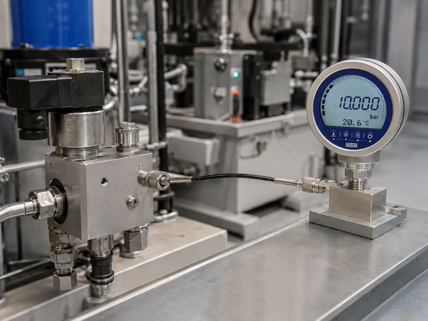
A MINIMESS test point is used on a system to check a comparatively low pressure. The reference measuring instrument is suitable for the range, but it indicates, for example, only 18 mbar even though approximately 25 mbar is expected in the process. This quickly leads to the assumption that the check valve inside the test point first requires part of the available pressure to open and that this pressure is therefore “lost” during the measurement.
This explanation is too simplistic for a correctly connected MINIMESS system. A conventional MINIMESS test point is not simply a spring-loaded check valve that must be opened solely by the process pressure. When the correct mating coupling is connected, the valve element is mechanically released. The spring force of the valve should therefore not simply be treated as a constant pressure offset during a static pressure measurement.
At very low pressures, MINIMESS measurements can nevertheless become more demanding. If the connection is not fully coupled, the valve cross-section may only be partially opened. In addition, the small nominal bore of the measuring hose, trapped air, hose elasticity, leaks and, in particular, differences in height between the measuring point and the pressure gauge have a much greater influence than in a conventional hydraulic measurement at 100 or 300 bar.
For low-pressure measurements via MINIMESS, the opening force of the check valve should therefore not simply be subtracted from the measured value. The decisive factors are whether the test point is fully mechanically opened and whether the hose, measuring instrument, medium and installation conditions are suitable for the very low pressure range.
How does a MINIMESS test point work?
A MINIMESS test point provides temporary access to a fluid system without requiring a permanently installed pressure gauge for every measurement. When no measuring device is connected, a valve element closes the process connection. This allows the system to continue operating even without an attached measuring instrument. For measurement, a suitable mating coupling or MINIMESS measuring hose is screwed onto the test point.
When correctly coupled, the integrated valve is mechanically opened and the process chamber is connected to the measuring hose. This principle is crucial for assessing very low pressures: the process pressure does not first have to overcome a defined spring force, as would be the case with a purely pressure-actuated check valve, before a measuring connection is established.
This does not mean, however, that the test point has no influence whatsoever in the low-pressure range. Coupling condition, available flow cross-sections and the complete connection between process and sensor determine how quickly the pressure is transmitted and how the measuring point behaves during dynamic pressure changes.
Does the opening mechanism cause a pressure offset?
A common assumption is that because the test-point valve contains a spring, a certain pressure must first build up before the valve opens. This value would then supposedly be missing from the pressure indicated by the measuring instrument. With a correctly coupled, mechanically released MINIMESS test point, this interpretation is not correct for a static pressure measurement.
If the valve travel is fully released and there is no significant continuous flow, the same hydrostatic or static pressure will, after sufficient time, generally be established on both sides of the connection – apart from effects such as height difference, temperature or an actual leak. A small cross-section does not by itself create a permanent pressure loss under static equilibrium conditions.
| Situation | Influence on measured value | Assessment |
|---|---|---|
| Test point fully mechanically opened, static pressure | No simple “opening pressure” correction required | After pressure equalization, the same static pressure should be present |
| Test point only partially opened | Very small free cross-sections and long settling times possible | Check coupling and mating connector |
| Pressure changes rapidly | Restricting effect of test point and hose may become visible | Consider dynamic measurement separately |
| Continuous flow through measuring line | Pressure loss across restrictions possible | Do not treat this as pure static pressure transmission |
What happens if the valve is not fully opened?
Problems arise if the mating coupling does not match the MINIMESS series, has not been screwed on completely or the opening mechanism does not mechanically reach its intended travel. The internal valve may then only be partially opened. At high pressure, this may hardly be noticeable because equilibrium can still be reached quickly enough despite the restricted cross-section.
At only a few millibar, the same condition can become much more noticeable. The volume of medium available for pressure transmission is small and, together with a flexible hose or trapped air, the indicated pressure may follow the actual process pressure only very slowly. If the value is read before complete stabilization, the measurement may appear too low.
The correct mating coupling is therefore more important than the external similarity of the components. With MINIMESS, the coupling side and the process connection thread must be considered separately. A test point from the 1620 series has the corresponding 1620 coupling system on the measuring side and must be connected to a compatible mating coupling.
Distinguishing static and dynamic pressure measurement
With a constant process pressure, only pressure equalization effectively needs to take place inside the measuring hose. Once equalization is complete, ideally no continuous volume flow remains. Pressure losses across the test point and hose are therefore far less relevant than during actual flow.
The situation is different with pulsating or rapidly changing pressures. The test point, microbore hose, trapped air and sensor volume together form a dynamic system. Small cross-sections act as restrictions, while compressible volumes can act as storage elements. Rapid pressure peaks may therefore be damped or delayed before reaching the measuring instrument.
| Measurement task | Typical influence of MINIMESS connection | What to consider |
|---|---|---|
| Constant pressure | Low influence after sufficient stabilization | Consider settling time and height difference |
| Slowly changing pressure | Delay possible with small opening or long hose | Observe the indication for sufficient time |
| Rapid pressure pulsations | Damping and phase shift possible | Use the shortest possible hose and suitable dynamic response |
| Measuring line with actual flow | Flow-related pressure loss possible | Do not treat as purely static pressure transmission |
Influence of the MINIMESS hose and internal volume
MINIMESS measuring hoses are deliberately designed as microbore lines. The small internal volume is advantageous for many diagnostic applications because only a small amount of medium is displaced during coupling and compact hose assemblies can be used. For the majority of hydraulic pressure measurements, this is a very practical solution.
In the extremely low-pressure range, however, the complete measuring line should be considered. A longer hose has more internal volume and more elastic wall area than a short connection. If a compressible gas is also present in the system, this volume must first be compressed or expanded before the sensor sees the final pressure. This increases the settling time.
For static low-pressure measurement, a measuring hose that is as short as possible and suitable for the medium and pressure is therefore advisable. The hose should not be routed in unnecessarily large loops if pressures of only a few millibar need to be assessed reliably.
Why height differences become critical at low pressures
With liquids, the hydrostatic height difference between the test point and the pressure sensor can be significantly greater than all the other effects discussed. If the measuring instrument is located above or below the process measuring point, the liquid column in the hose generates an additional pressure difference.
For water, as a rough approximation, a height difference of only 10 cm corresponds to approximately 9.8 mbar. If a process pressure of only 25 mbar is to be assessed, this height difference already represents almost 40% of the actual measured value. In a 200 bar hydraulic application, the same effect would be practically negligible.
The magnitude can be estimated using Δp = ρ × g × Δh. Here, ρ is the density of the medium, g is gravitational acceleration and Δh is the difference in height. With liquids, especially at low pressures, it should therefore be clearly defined which reference height the measurement relates to.
Trapped air and venting
For purely static pressure transmission, trapped air does not automatically mean a constant measurement error. However, it can make the measurement considerably slower and more sensitive to temperature changes. Unlike liquids, gas is highly compressible. This changes the overall behavior of the measuring line.
A mixture of liquid and several air pockets inside the hose is particularly unfavorable. Pressure changes must first compress the trapped gas volumes. At the same time, changes in temperature can alter the volume and pressure of these gas pockets. At very low measuring pressures, this can become clearly visible.
If a liquid-filled measuring line is intended, it should therefore be filled reproducibly and vented according to the application. Conversely, in an intentionally pneumatic measurement, uncontrolled liquid columns should be avoided because they can introduce hydrostatic pressure contributions.
Selecting the correct measuring range
A MINIMESS connection can only provide meaningful results if the connected measuring instrument is suitable. A digital pressure gauge with a measuring range of, for example, 400 bar is not a meaningful reference if a pressure of 30 mbar is to be assessed. Resolution, zero stability and specified measurement uncertainty must match the actual measured value.
For such an application, a deliberately small measuring range is required. A portable instrument such as the Druck DPI705E, for example, is also available with gauge and differential pressure ranges starting from 25 mbar. However, the medium and pressure connection must always be compatible with the selected sensor version.
Before measurement, the zero point should also be checked under defined conditions. At only a few millibar, even a small zero error can represent a significant proportion of the measured value. This applies regardless of whether the sensor is connected directly or via a MINIMESS test point.
Systematically diagnosing measurement deviations
If a MINIMESS measurement in the low-pressure range shows an unexpected value, the test point should not immediately be assumed to be the cause. A much more useful approach is to compare it with a connection that is as direct as possible under the same conditions. This makes it possible to determine whether the deviation is actually related to the test point and hose or is already present in the process or measuring instrument.
| Observation | Possible cause | Next check |
|---|---|---|
| Indication rises very slowly to the expected value | Partially opened valve, long hose or trapped air | Check coupling, hose length and venting |
| Constant offset with liquid-filled hose | Height difference between test point and sensor | Compare reference heights |
| Direct connection correct, MINIMESS connection significantly slower | Flow restriction or additional volume | Fully open the coupling and shorten the hose |
| Value fluctuates with ambient temperature | Gas pockets or sensor zero drift | Check measuring line and measuring instrument separately |
| Only rapid pressure peaks are missing | Dynamic damping in the measuring line | Use a shorter measuring line or a more direct sensor connection |
Practical example: measuring 25 mbar via a MINIMESS test point
A low overpressure of approximately 25 mbar is to be checked in a lubricating-oil system. A MINIMESS 1620 test point is already installed on the system. A suitable low-pressure measuring instrument is connected via a long measuring hose and is positioned approximately 20 cm above the measuring point. The indicated value differs significantly from the expected pressure.
Initially, it is assumed that the spring inside the test point consumes part of the available pressure. In reality, however, the valve is mechanically opened when the connection is fully screwed on. Inspection instead shows that the measuring line is filled with liquid and that there is a relevant height difference between the process connection and the sensor. With a water-like medium, a liquid column of only 20 cm can already produce a hydrostatic pressure difference of approximately 20 mbar.
The measuring instrument is then positioned at the same height as the test point and the hose is shortened. After complete stabilization, the measured value agrees much better with the comparison measurement. The previously assumed “opening pressure” of the MINIMESS valve was not the cause.
This example shows why the magnitude of every possible influence must be considered when measuring very low pressures. An effect that is completely negligible at 200 bar can account for most of the measured value at 20 or 30 mbar.
Setting up low-pressure measurement correctly
- Determine the actual pressure range: Select the measuring instrument according to the specific measurement task, not according to the maximum possible system pressure.
- Use the correct MINIMESS series: Test point and mating coupling must be mechanically compatible and fully coupled.
- Keep the measuring hose as short as possible: Avoid unnecessary internal volume and additional dynamic effects.
- Consider the reference height: With liquids, position the sensor and measuring point at approximately the same height or account for the hydrostatic contribution.
- Fill or vent the measuring line in a defined manner: Avoid uncontrolled gas and liquid pockets.
- Allow sufficient stabilization time: Especially at very low pressure, do not read the value immediately after connection.
- Carry out a comparison measurement if in doubt: Compare the MINIMESS setup with a direct process connection.
Common mistakes
- Treating the valve spring as a fixed pressure offset: The MINIMESS test point is mechanically released when correctly coupled.
- Failing to connect completely: A partially opened coupling can significantly slow pressure transmission.
- Using a 400 bar pressure gauge for 20 mbar: Measuring range, resolution and zero stability are not suitable for the task.
- Ignoring height differences: With liquids, even a few centimeters can generate a relevant pressure contribution.
- Using unnecessarily long hoses: Greater volume and elasticity can increase settling time.
- Treating static and dynamic measurement as the same: A connection that transmits a constant pressure correctly does not necessarily reproduce rapid pressure peaks unchanged.
- Reading the value too early: With small cross-sections and compressible volumes, the indication may require significantly more time to stabilize.
MINIMESS components for temporary pressure measurements
For conventional service and diagnostic tasks, the original Hydrotechnik MINIMESS 1620 test point is a widely used solution. It has an M16 × 2 coupling thread and allows measuring instruments to be connected while the system is operating. Depending on the version, different process threads, materials and sealing options are available.
Suitable MINIMESS measuring hoses are available for connection to the test point. A DN2 microbore hose is frequently used for conventional pressure measurements. In addition to the MINIMESS series, the connection to the measuring instrument, hose length, pressure range, temperature, medium and sealing materials must also be considered when selecting the hose.
Suitable components can be found under MINIMESS couplings and hoses at ICS Schneider. Further information is also available for the original MINIMESS 1620 test point and the MINIMESS hoses.
Conclusion
A MINIMESS test point can generally also transmit low static pressures. The spring of the integrated check valve should not be interpreted as a simple minimum opening pressure that has to be subtracted from the process pressure. When connected correctly, the valve is mechanically released.
At very low pressures, however, other characteristics of the measuring setup become more significant. An incompletely coupled connection can severely restrict the available cross-section and increase the settling time. A long microbore hose and trapped gas volumes can additionally delay or damp pressure changes.
With liquid media, the height difference is often the most important influence. Just a few centimeters of liquid column correspond to several millibar. At the same time, the measuring instrument used must actually be suitable for the low pressure in terms of measuring range, zero stability and measurement uncertainty.
For reliable low-pressure measurements via MINIMESS, the following therefore applies: fully mechanically open the test point, use a short and suitable measuring line, control height differences and filling conditions, allow sufficient time for stabilization and use a measuring instrument that matches the actual pressure range.
FAQ: MINIMESS at very low pressure
Does a MINIMESS test point require a minimum pressure to open?
A conventional MINIMESS test point is mechanically released when the correct mating coupling is connected. The spring force should therefore not be interpreted as a fixed minimum pressure or pressure offset during a correctly coupled static pressure measurement.
Can MINIMESS be used to measure pressures in the millibar range?
In principle, static pressure can be transmitted. However, the lower the pressure, the more important the sensor measuring range, complete valve opening, hose routing, trapped air, height differences and sufficient stabilization become.
Can the check valve cause a pressure reading that is too low?
With correct and complete mechanical opening, the valve spring does not simply create a constant pressure loss under static equilibrium conditions. However, incomplete opening can significantly slow pressure transmission and can lead to deviations during dynamic processes.
Does a MINIMESS hose affect static pressure?
After complete pressure equalization, a small hose cross-section alone does not cause a permanent static pressure loss. It can, however, influence settling time and the transmission of rapid pressure changes.
Why is height difference so important at low pressures?
A liquid column generates hydrostatic pressure. With water, a height difference of approximately 10 cm already corresponds to around 9.8 mbar. For a measurement of only 20 or 30 mbar, this is a very large influence.
Does air inside the MINIMESS hose affect the measurement?
Trapped air increases the compressibility of the measuring system and can significantly delay pressure transmission and make it more temperature-sensitive. Under static equilibrium conditions, however, it does not automatically cause a fixed pressure offset.
Why does the measured value initially appear too low directly after connection?
Possible causes include a coupling that is only partially opened, a long microbore hose or compressible gas volumes. The pressure then requires more time to equalize between the process and sensor.
Which MINIMESS test point is suitable for standard applications?
The original Hydrotechnik MINIMESS 1620 is a widely used standard series with an M16 × 2 coupling thread. The specific process connection, material and sealing version must match the application.
Which measuring instrument is suitable for pressures of only a few millibar?
A pressure measuring instrument with a correspondingly small measuring range should be used. The Druck DPI705E, for example, is also available with a 25 mbar gauge-pressure range.
How can you check whether the MINIMESS setup is influencing the measured value?
The most meaningful method is a comparison measurement under identical conditions: once via the test point and measuring hose, and once via a process connection that is as direct as possible. Reference height, medium and measuring instrument must either be identical or properly taken into account.