


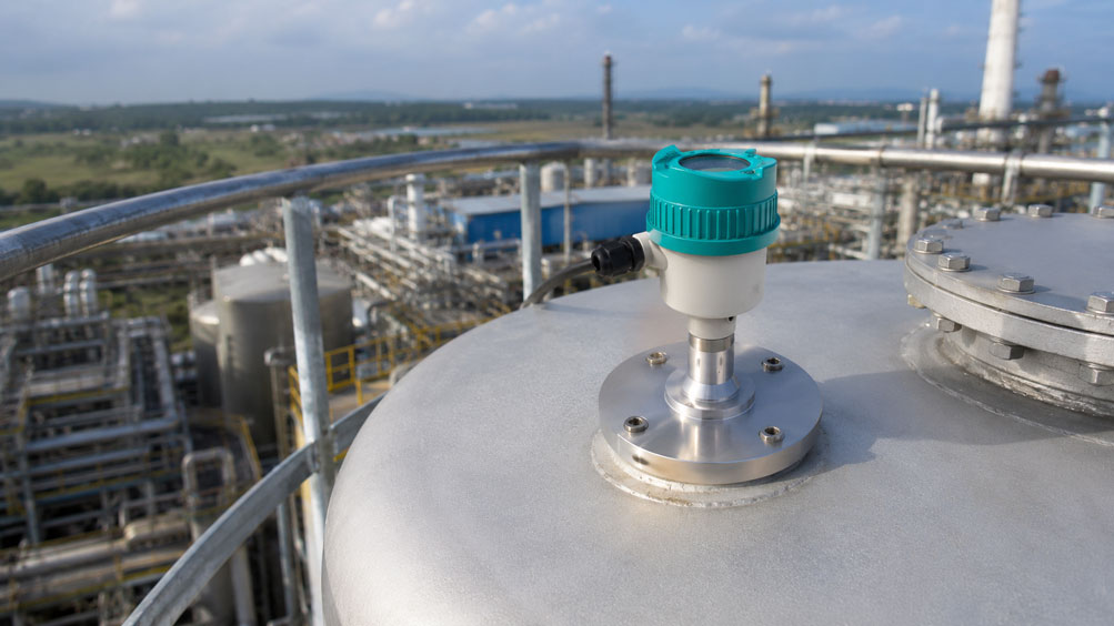
A storage tank is 35 m high and is to be monitored using a non-contact radar level transmitter. According to the datasheet, the selected device has a measuring range that easily covers this distance. Nevertheless, sporadic measurement jumps occur at low level. Does this mean the radar level sensor is unsuitable?
Not necessarily. Especially in tall vessels, the maximum measuring range is not the only decisive factor. As the distance increases, the area detected by the sensor on the product surface becomes larger. At the same time, vessel walls, ladders, pipes, braces, agitators or other internal structures can generate additional echoes.
The beam angle of the radar antenna is therefore a very important parameter. A narrow radar beam makes it easier to maintain a clear measuring path through a tall vessel. Modern 80 GHz devices can focus the beam much more narrowly than older radar technologies operating at lower frequencies.
For tall tanks, it is therefore not sufficient to check only whether the nominal measuring range is adequate. Antenna size, beam angle, mounting position, vessel internals, product surface and available echo quality must all be considered together.
How does non-contact radar level measurement work?
A radar level transmitter sends electromagnetic signals toward the product surface. Part of this energy is reflected there and received again by the sensor.
The distance between the antenna and the product surface is determined from the signal travel time. In simplified form:
Distance = vessel height - level
Because no probe is immersed in the medium, the method is non-contact. It is therefore suitable, among other applications, for aggressive liquids, high temperatures, pressurized vessels and applications where mechanical components in the medium are to be avoided.
The key requirement, however, is that the useful echo from the product surface can be detected clearly.
Why do tall vessels become more demanding?
The greater the distance between the radar antenna and the product surface, the more demanding the geometric design of the measuring point becomes.
There are several reasons for this:
- the radar beam becomes wider as the distance increases,
- more vessel internals can enter the beam area,
- the reflected energy can become weaker,
- weak false echoes can become more relevant compared with the useful signal,
- mounting errors have a greater effect over long distances.
A sensor can therefore have a nominal measuring range of, for example, 120 m and still be poorly installed. Measuring range and installation conditions are two different selection criteria.
What does the radar antenna beam angle mean?
The radar beam is not an infinitely thin mathematical line. The transmitted energy is distributed within a defined angle.
This beam angle determines how wide the relevant measuring area becomes as the distance increases.
For the Siemens SITRANS LR530, the beam angle depends on the antenna or flange size. Typical values are:
| LR530 version | Beam angle | Recommended measuring range |
|---|---|---|
| from DN25 | approx. 10° |
up to 20 m |
| from DN50 / 2″ | approx. 6° |
up to 30 m |
| from DN80 / 3″ | approx. 3° |
up to 120 m |
For very tall vessels in particular, the larger antenna is therefore relevant not only because of the maximum measuring range. The smaller beam angle also makes it easier to geometrically separate useful reflections from false reflections.
How large does the radar beam become inside the vessel?
The approximate diameter of an idealized radar beam can be estimated from the measuring distance and beam angle.
In simplified form:
Beam diameter ≈ 2 × distance × tan(beam angle / 2)
With a beam angle of 3°, for example, the diameter at a distance of 30 m is approximately:
1.57 m
At a distance of 100 m, it would already be approximately:
5.24 m
This simple geometric consideration does not replace the manufacturer’s design of the actual antenna field. However, it clearly illustrates why an installation that appears unproblematic directly at the sensor can require several metres of clear space at the lower end of a very tall tank.
Why does antenna size influence the measuring range?
The antenna largely determines how strongly the radar energy is focused. A larger effective antenna can generate a narrower beam.
For the SITRANS LR530, the maximum recommended measuring range is therefore linked to the flange size. A DN25 version does not simply become a 120 m solution because the electronics are fundamentally capable of measuring long distances.
For tall vessels, the following should therefore already be taken into account during device selection:
- required maximum measuring distance,
- flange size,
- beam angle,
- available mounting opening,
- position of vessel internals.
A larger antenna can therefore provide a measurement advantage in a tall tank and is not merely a mechanical connection variant.
Where should the radar level sensor be installed?
The best position is generally where the radar beam can reach a representative product surface with as little interference as possible.
Positions directly above or immediately next to the following are particularly unfavourable:
- filling pipes,
- ladders,
- agitator shafts,
- heating coils,
- bracing,
- large pipelines,
- other strongly reflecting internals.
The geometric design should not consider only the condition when the tank is full. Especially at low level, the radar beam is widest and can therefore detect more distant internals.
Why should the radar beam not hit the vessel wall?
A metallic vessel wall reflects radar energy very effectively. If a significant part of the measuring beam hits the wall, an additional strong echo can be generated.
This can be particularly problematic if the sensor is mounted at a slight angle. Even a small angular misalignment has a significant effect over a long measuring distance.
In a very tall tank, an apparently small deviation of the antenna axis can therefore cause the radar beam to be displaced sideways by several metres in the lower section.
During installation, flange, gasket, nozzle and mechanical alignment should therefore be designed so that the intended measuring direction is actually maintained.
Which vessel internals generate false echoes?
In principle, any surface that reflects radar energy can generate an echo.
Typical false reflectors in process vessels include:
- ladders,
- pipelines,
- agitator shafts and blades,
- heating and cooling coils,
- bracing,
- filling and discharge pipes,
- vessel roof structures,
- weld seams or large protrusions,
- nozzles and internal flanges.
Not every internal component automatically causes a measurement error. What matters is how strong its echo is compared with the actual level echo and whether it lies within the relevant measuring range.
Taking filling flow and product surface into account
The product surface itself is not always calm and horizontal.
During filling, the following can occur:
- turbulence,
- waves,
- foam,
- splashes,
- changing surface slopes.
A radar level sensor should therefore, where possible, not measure directly into the filling stream.
A product stream entering from the side can both alter the surface and act as an additional reflecting surface itself.
Especially in tall vessels, the mounting position should therefore be evaluated for actual filling operation and not only for the static tank condition.
What do echo quality and signal margin mean?
For reliable measurement, the sensor must clearly distinguish the echo from the product surface from noise and unwanted reflections.
In simplified terms, this can be described as signal margin: how clearly does the relevant level echo stand out from false signals or noise?
This margin depends, among other things, on:
- antenna size,
- measuring distance,
- dielectric constant of the medium,
- surface condition,
- vessel geometry,
- internals,
- deposits on the antenna.
A reliable system should not merely detect an echo under ideal conditions. There should also be sufficient signal margin when process conditions change.
How does false-echo suppression work?
Fixed vessel internals often generate reflections at the same distance every time.
Modern radar level transmitters can detect such known reflections and suppress them or assign them a lower weighting during subsequent signal processing.
The SITRANS LR530 provides automatic false-echo suppression for fixed vessel internals.
However, this does not mean that an arbitrarily poor installation can automatically be corrected.
Good mechanical installation always remains the first measure. False-echo suppression is an additional signal-processing function and not a substitute for a clear measuring path.
Why is the echo profile important for diagnostics?
An echo profile shows the reflections received by the radar sensor over the measuring distance.
This makes it possible to identify, for example:
- where the actual level echo is located,
- whether strong fixed false echoes are present,
- how the signal changes as the level drops,
- whether deposits or process conditions have changed.
With the SITRANS LR530, a graphical echo profile display is part of the local user interface. This allows a problematic measuring point to be diagnosed much more precisely than by looking only at a fluctuating 4…20 mA value.
Practical example: tall tank with ladder and piping
A storage tank has a height of 32 m. Inside the tank there is a vertical ladder and a pipeline that runs along the wall over part of the vessel height.
Initially, a radar level sensor with a relatively wide beam is installed on an existing roof nozzle.
At high level, the measurement works without problems because the product surface is only a few metres from the antenna.
As the level falls, however, the radar beam becomes wider. Eventually, the ladder enters the relevant beam area to a greater extent.
The sensor now detects a strong fixed echo from the ladder in addition to the weakening product echo.
The measuring point is then reassessed. The sensor is configured with an antenna version providing a narrower beam angle, and the mounting position is selected so that the measuring beam passes the ladder and piping as freely as possible.
In addition, the echo profile is recorded with an empty or low tank and the fixed reflection is taken into account accordingly.
This example shows that a radar sensor can work perfectly with a full vessel and only start to experience problems at low level because the geometrically detected area increases with measuring distance.
Systematic design procedure
- Determine the maximum measuring distance: Take into account the distance between the antenna and the minimum level.
- Document vessel height and vessel diameter.
- Take the medium and its reflection properties into account.
- Select a suitable radar frequency and antenna.
- Check the beam angle of the specific antenna.
- Consider the approximate beam area over the complete measuring distance.
- Enter ladders, pipes, agitators and other internals in the vessel drawing.
- Select a mounting position with as clear a radar path as possible.
- Avoid the filling stream and highly turbulent areas.
- Mechanically align flange and sensor axis correctly.
- Check the echo profile after commissioning.
- Use false-echo suppression only selectively and after checking the actual echo conditions.
- Evaluate the measuring point at low level as well.
Common mistakes
- Checking only the maximum measuring range: A sufficient value in metres does not guarantee interference-free measuring geometry.
- Ignoring the beam angle: The radar beam becomes wider as the distance increases.
- Considering only the full-tank condition: Vessel internals may enter the beam only at low level.
- Aiming the sensor directly at a ladder or pipeline: This can generate strong fixed false echoes.
- Accepting the filling stream directly below the antenna: Moving liquid, splashes or foam can make echo evaluation more difficult.
- Underestimating small angular errors in tall tanks: Over long distances, they can create a considerable lateral displacement.
- Using false-echo suppression as a substitute for poor installation: Signal processing should complement good geometry, not replace it.
- Selecting antenna size only according to flange availability: It also influences beam angle and recommended measuring range.
- Failing to check the echo profile: Problematic reflections can remain undetected during commissioning.
SITRANS LR530 for tall process and storage tanks
One specific 80 GHz radar level transmitter for liquids and slurries is the Siemens SITRANS LR530.
The device features an encapsulated PTFE antenna with flange connection. Depending on the flange size, the recommended measuring range extends from 20 m up to a maximum of 120 m.
For very large distances, the version from DN80 or 3″ is particularly relevant. Here, the beam angle is approximately 3° and the recommended measuring range is up to 120 m.
The 80 GHz technology enables a narrowly focused radar beam and therefore reduces sensitivity to vessel internals.
Diagnostic functions include:
- graphical echo profile display,
- automatic false-echo suppression,
- near-range suppression,
- Process Intelligence signal processing,
- NE107 diagnostic functions
.
Further information can be found under Siemens SITRANS LR530 and under level measurement technology at ICS Schneider.
Conclusion
For radar level measurement in a tall vessel, it is not sufficient simply to select a sensor with a sufficiently large nominal measuring range.
As the measuring distance increases, the relevant radar area becomes larger. This means that vessel walls, ladders, pipelines, agitators and other internals can have a greater influence on echo evaluation.
A narrow beam angle is therefore particularly helpful in tall vessels. Modern 80 GHz radar sensors can focus the measuring energy very tightly and thus provide a largely unobstructed measuring path even in more complex vessels.
Antenna size, measuring range and beam angle are closely related. For the SITRANS LR530, the recommended measuring range extends from 20 to 120 m depending on flange size, while the beam angle decreases from approximately 10° to as little as 3°.
However, even modern signal processing does not replace good installation. Automatic false-echo suppression and echo-profile analysis are valuable diagnostic tools, but they should be based on sensible measuring geometry.
For tall vessels, the following therefore applies: consider maximum measuring distance and radar beam together, take vessel internals into account over the entire height, align the antenna correctly and check echo quality especially at low level.
FAQ: Radar level measurement in tall vessels
Which radar sensor is suitable for very tall tanks?
For large measuring distances, radar sensors with sufficient measuring range and a narrow beam angle are suitable. One example is the Siemens SITRANS LR530, which provides measuring ranges of up to 120 m depending on antenna size.
Why is the beam angle important in tall vessels?
The radar beam becomes wider as the distance increases. A small beam angle therefore reduces the probability that the vessel wall or internals will enter the relevant measuring area.
What beam angle does the SITRANS LR530 have?
Depending on flange size, the beam angle is approximately 10°, 6° or 3°.
Can the SITRANS LR530 always measure 120 m?
No. The recommended maximum measuring range depends on the flange or antenna size. DN25 is intended for up to 20 m, DN50 or 2″ for up to 30 m, and DN80 or 3″ and larger for up to 120 m.
Why does a radar sensor work with a full tank but not with an empty tank?
At low level, the measuring distance is greater and the area detected by the radar is wider. Additional vessel internals or weaker echo conditions can therefore become relevant.
Which vessel internals can interfere with radar measurement?
Typical examples include ladders, pipelines, agitator shafts, heating coils, braces and other metallic structures.
What is false-echo suppression?
The transmitter detects or stores fixed reflections from known vessel internals and takes them into account accordingly during subsequent signal evaluation.
Can false-echo suppression completely compensate for poor installation?
No. A clear radar path and good mounting geometry remain the most important basis for reliable measurement.
Why is the echo profile useful?
It shows the received reflections over distance. This makes it much easier to distinguish and diagnose the level echo and fixed false echoes.
Does antenna size only matter for the process connection?
No. Antenna size also influences beam angle and the recommended maximum measuring range.
Why should the sensor not be mounted directly above the filling point?
Incoming medium can generate turbulence, splashes, foam and additional reflections, making echo evaluation more difficult.
Which specific device is suitable for tall liquid tanks?
One example is the Siemens SITRANS LR530 with 80 GHz radar technology, encapsulated PTFE antenna and flange connection. From DN80 or 3″, a recommended measuring range of up to 120 m is possible with a beam angle of approximately 3°.