


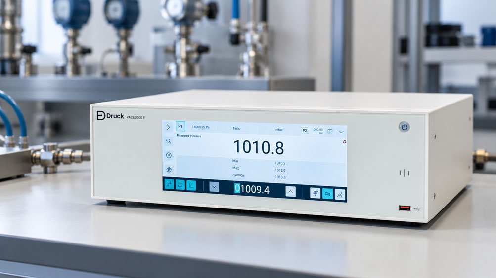
A calibration laboratory needs to test pressure sensors with measuring ranges of 0 ... 1 bar, 0 ... 10 bar and 0 ... 70 bar. A pressure controller with a 70-bar module can generally cover the required pressure range. Nevertheless, an important question remains: Is this module also the metrologically best reference at a test pressure of, for example, 500 mbar?
Not necessarily. The decisive factor is not only whether a pressure controller can generate a certain pressure. For calibration, it must also be checked what measurement uncertainty or accuracy the active reference provides at this pressure. Particularly with specifications containing a component related to full scale, a large reference range can be disadvantageous at low pressures.
Modular pressure controllers can therefore be equipped with multiple measurement or control ranges. With auto-ranging, these ranges are available simultaneously and the system can use the appropriate range depending on the required test pressure. This allows a large overall pressure range to be covered without having to manually connect a different reference instrument for each test task.
Auto-ranging therefore does not simply extend the available pressure range. When used correctly, it ensures that an appropriate reference range is used for both low and high test pressures and prevents the measurement uncertainty from being unnecessarily worsened by an excessively large measuring range.
Why does the measuring range influence measurement uncertainty?
With a pressure controller, the quality of a measurement is not determined solely by the number of digits shown on the display. The specification of the pressure measurement module used is decisive.
Part of the error specification may, for example, be related to the measured value, while another part may be related to the measuring range or full scale. A full-scale component in particular remains as an absolute pressure value even when only a small part of the measuring range is being used.
A highly simplified example illustrates the principle. Assume that two reference modules have the same relative full-scale component:
| Module | Full-scale range | Same assumed FS component | Resulting absolute component |
|---|---|---|---|
| Low-pressure module | 1 bar |
x % FS |
x % of 1 bar |
| High-pressure module | 70 bar |
x % FS |
x % of 70 bar |
Although the percentage value would be identical, the absolute error contribution would be correspondingly larger with the 70-bar module.
The actual specifications of a specific PACE module must, of course, be taken from its datasheet or calibration documentation. The example merely demonstrates why range selection can fundamentally influence the achievable uncertainty.
What does an accuracy specification in % FS mean?
FS stands for Full Scale, meaning the upper end of the measuring range.
If a pressure module has, for example, a range of:
0 ... 10 bar
then:
FS = 10 bar
An error component specified in percent FS is related to this full-scale value and not to the pressure currently being measured.
This is precisely why, for a calibration task involving low pressures, it should be checked whether a smaller available reference range can be used.
Distinguishing % of reading from % of full scale
A specification in percent of reading behaves differently from a specification in percent of full scale.
| Specification | Reference quantity | Behaviour at low test pressure |
|---|---|---|
% of reading |
Currently measured pressure | Absolute error contribution also becomes smaller as the pressure decreases |
% FS |
Full-scale value | Absolute contribution remains dependent on the range end value |
| Combined specification | Measured value + FS or additional components | Both contributions must be taken into account |
With high-quality pressure references, long-term stability, temperature, calibration uncertainty, zero behaviour and other components can additionally be part of the specification or measurement uncertainty budget.
A single value from a datasheet should therefore never be interpreted without its full reference framework.
Why are multiple measurement modules useful?
A calibration laboratory often handles devices under test with very different pressure ranges. A single very large module may be able to generate many of these pressures, but it is not necessarily metrologically optimal for every part of the range.
A modular solution can, for example, combine two ranges:
- a precise low-pressure range for low-pressure sensors,
- a larger pressure range for industrial high-pressure transmitters.
This makes both reference ranges available without mechanical reconfiguration.
The user does not need to switch between several separate pressure controllers and at the same time reduces the risk of accidentally using an unfavourable reference range for a low-range device under test.
How does auto-ranging work?
With auto-ranging, multiple installed measurement or control ranges are available within the same system.
The pressure controller uses the suitable available range depending on the required pressure. The objective is to achieve the best possible metrological performance over a large overall pressure range.
A typical laboratory system could, for example, contain:
- Module A: low pressure range,
- Module B: high pressure range.
At low test pressures, the smaller range is used. If the required pressure exceeds the available range of the smaller module, the larger range becomes available.
With the Druck PACE6000E, two control modules can be installed and operated, among other modes, in auto-ranging mode.
What happens when switching between ranges?
The switch between two reference ranges should not be treated as an invisible process from a metrological perspective.
For high-quality calibration, it is important to know which range is active at each test point. In particular, when a measurement series crosses the switching range, different module specifications can affect the uncertainty calculation.
A test procedure should therefore be designed so that:
- the modules used are clearly identified,
- their valid calibrations are available,
- the respective specifications are taken into account,
- range changes remain traceable.
Auto-ranging removes the need for manual range selection. However, it does not remove the metrological responsibility for the reference ranges being used.
Which reference range is suitable for the device under test?
The reference should be selected so that it can safely generate and measure the required test pressure while also providing sufficiently low measurement uncertainty.
A device under test with a measuring range of 0 ... 1 bar should not automatically be tested with the largest reference range available in the laboratory.
A more suitable reference range is one that:
- covers the complete required test pressure,
- provides sufficient overpressure margin for the intended test sequence,
- offers suitable measurement uncertainty,
- matches the required pressure type.
However, the smallest available range is not automatically always the correct choice either. It must safely cover all intended test points, including any required preloads.
Why is the ratio between reference and device under test important?
During calibration, the reference should be significantly more accurate than the device under test. The required ratio depends on the quality and calibration procedure being applied.
Often, the relationship between the tolerance of the device under test and the measurement uncertainty of the reference or the complete calibration process is considered.
A large reference pressure range can worsen this ratio, particularly in the lower part of the range, if relevant uncertainty components are related to full scale.
Auto-ranging can therefore help achieve a more favourable relationship between device under test and reference over a large overall pressure range.
Do not confuse measuring range and control range
In a pressure controller, the active module does not only perform a measurement function; it is also part of the complete pneumatic control loop.
For device selection, several characteristics must therefore be considered separately:
- measuring range,
- control range,
- measurement uncertainty or accuracy,
- control stability,
- control speed,
- permissible supply pressure.
A module that can measure a pressure does not automatically have to be optimal for every desired control task.
With large external volumes, very low test pressures or fast test sequences, dynamic control performance therefore also plays a role.
Why must the pressure be allowed to stabilize after a pressure change?
An automatic pressure controller can approach a new setpoint very quickly. For the actual calibration reading, however, a defined stable condition must then be reached.
The required time depends, among other things, on:
- test volume,
- hose volume,
- device under test,
- pressure level,
- control parameters,
- thermal effects.
High control convenience must therefore not result in a test point being documented immediately after the setpoint is reached while the pressure or device under test has not yet stabilized sufficiently.
For automated calibration sequences, suitable stability or in-limits criteria should be used.
Practical example: 1-bar and 70-bar modules in one controller
A calibration laboratory tests different pressure transmitters from a few hundred millibar up to 70 bar.
As an example, the PACE6000E is equipped with two suitable control modules:
| Module | Pressure range | Typical test task |
|---|---|---|
| Module A | 0 ... 1 bar |
Low-pressure sensors and small process ranges |
| Module B | 0 ... 70 bar |
Industrial pressure transmitters with higher ranges |
First, a sensor with a range of 0 ... 600 mbar is to be tested.
The 70-bar range could generally generate this pressure. However, for the reference measurement, the smaller range is much better matched to the test task.
A 0 ... 40 bar transmitter is then tested. This range lies outside the smaller module, so the larger reference range is required.
In auto-ranging mode, both ranges are available without manually changing modules.
The advantage is therefore not that two modules are combined to create one new sensor. Rather, two calibrated reference ranges are available, between which the system can switch according to the respective pressure task.
Considering auto-ranging in the measurement uncertainty budget
For traceable calibration, the measurement uncertainty must be determined for the actual measurement condition used.
This can include, among other things:
- uncertainty of the reference calibration,
- specification of the active pressure module,
- long-term stability,
- resolution,
- repeatability,
- zero behaviour,
- temperature conditions,
- pressure stability during the reading.
If different modules are used within one measurement series, different measurement uncertainties may therefore apply to different test points depending on the laboratory procedure.
It would be incorrect simply to apply the best specification of the entire controller to all test points.
Which range must be documented?
For a traceable calibration, it should be clear which reference or active measuring range was used to generate and measure each individual test point.
This is particularly important when:
- multiple modules have different specifications,
- different calibration data apply,
- different recalibration dates exist,
- an auto-range change occurs within the test range.
In automated test systems, this information can ideally be logged directly together with the measured values.
Auto-ranging should simplify operation, but it must not reduce the traceability of the reference used.
Systematic module selection
- Record all regularly occurring device-under-test ranges.
- Determine the required maximum and minimum test pressures.
- Define required DUT tolerances or target measurement uncertainties.
- Compare available CM or CM3 pressure ranges.
- Calculate accuracy and uncertainty specifications over the range actually used.
- Combine ranges so that unfavourable edge regions are minimized.
- Determine which range is intended for which DUT group.
- Define the auto-ranging or switching strategy.
- Define stability criteria for automated readings.
- Document the active reference range in the calibration sequence.
- Monitor calibration intervals of the individual modules.
Common mistakes
- Considering only the highest required pressure: A large pressure range can have unnecessarily unfavourable measurement uncertainty at low pressures.
- Confusing resolution with accuracy: Many display digits do not automatically mean correspondingly low measurement uncertainty.
- Confusing % FS with % of reading: The two specifications have very different effects at low pressures.
- Always using the largest installed range: This wastes the metrological advantage of a smaller reference range.
- Always forcing the smallest range: The required test pressure, including all test conditions, must remain safely within the permissible range.
- Treating auto-ranging as one single continuous specification: The characteristics of the modules actually used remain decisive.
- Failing to document range changes: This can result in loss of traceability within the uncertainty budget.
- Considering only short-term accuracy: Long-term stability and calibration uncertainty must also be taken into account.
- Reading the test point immediately after pressure regulation: Reaching the setpoint does not automatically mean that a sufficiently stable calibration point has already been reached.
- Equating the controller base unit with measurement accuracy: The achievable measurement performance is largely determined by the control module being used.
PACE6000E with CM and CM3 control modules
A specific modular high-precision pressure controller for this application is the Druck PACE6000E.
The dual-channel chassis can be equipped with up to two PACE CM or CM3 control modules. The modules contain the components relevant to pressure measurement and pressure control and can be selected for different pressure ranges.
With two modules, the PACE6000E can be used in three basic operating modes, among others:
- Single: use of one pressure channel or range,
- Auto-Ranging: automatic use of suitable ranges across an extended pressure range,
- Dual Channel: two independent pressure tasks simultaneously.
For particularly demanding calibration applications, optional CM3 control modules with TERPS sensor technology are available. Depending on the selected module, the pressure range and metrological specification differ.
It is therefore also important with the PACE6000E to understand that measurement accuracy is not determined by the base unit alone, but largely by the installed control module.
Further information can be found under Druck PACE6000E high-precision pressure controller and under calibration technology at ICS Schneider.
Conclusion
A large pressure measuring range is not automatically the best reference for high-quality pressure calibration over the entire range.
In particular, when parts of the measurement uncertainty are related to the full-scale value, smaller reference ranges can provide a significant metrological advantage at low pressures.
A modular pressure controller therefore enables different ranges to be combined in a single system. With auto-ranging, a suitable available range can be used depending on the required test pressure.
This not only reduces manual reconfiguration. Different devices under test can also be calibrated with reference ranges that are better matched to their respective pressure spans.
However, auto-ranging does not replace uncertainty analysis. For each test point, the specification of the measurement module actually used remains decisive. Range changes, calibration data, long-term stability and the other contributions to the measurement uncertainty budget must still be taken into account.
For optimum configuration, the following therefore applies: do not simply select the largest possible pressure range, but analyse the regularly required test pressures, combine suitable modules and use auto-ranging deliberately in order to achieve the most favourable measurement uncertainty possible over the complete working range.
FAQ: Auto-ranging with modular pressure controllers
What does auto-ranging mean in a pressure controller?
Auto-ranging means that multiple available pressure ranges within one system can be used and that a suitable range is selected depending on the current pressure task.
Why can a smaller measuring range be more accurate?
If relevant error components are related to full scale, their absolute pressure value is correspondingly smaller with a smaller full-scale range.
What does % FS mean?
FS stands for Full Scale. A specification in percent FS refers to the upper limit of the respective measuring range and not to the pressure currently being measured.
What is the difference between % FS and % of reading?
A percent-of-reading component changes with the current pressure. A full-scale component, on the other hand, is calculated from the end value of the measuring range used.
Is auto-ranging only a convenience function?
No. In addition to eliminating manual range changes, auto-ranging can also provide a metrological advantage because a suitable smaller reference range can be used at low pressures.
Can a 70-bar module also measure at 1 bar?
In principle, a large measuring range can measure lower pressures as long as they lie within the specified range. For calibration, however, it must be checked whether the resulting measurement uncertainty is sufficient for the device under test.
Is the smallest available range always the best?
No. The reference range must safely cover all required test points and test conditions. The decisive factor is the combination of sufficient range and suitable measurement uncertainty.
Does a range change during auto-ranging need to be documented?
For traceable and metrologically transparent calibrations, it should be clear which reference range or module was used for the respective test points.
Does the entire auto-range span have one single measurement uncertainty?
Not necessarily. If different modules are used, their specifications and calibration uncertainties can differ. The reference range actually used must be taken into account for each test point.
How many control modules can the PACE6000E accommodate?
The PACE6000E is designed as a dual-channel system and can be equipped with up to two control modules.
What is the difference between auto-ranging and dual channel?
With auto-ranging, different available ranges are used for one pressure task. In dual-channel operation, two independent pressure tasks or control channels can be operated simultaneously.
What are CM3 modules?
CM3 modules are optional high-precision control modules for PACE systems. They use Druck’s TERPS sensor technology and are designed for particularly demanding calibration and reference measurements.
Is the accuracy determined by the PACE6000E or by the module?
The metrological performance is largely determined by the installed control module. An identical module therefore generally provides the same module-specific measurement performance regardless of whether it is used in a compatible PACE5000E or PACE6000E.